you might want to read thru these links and sub links it will help you avoid costly mistakes
http://www.summitracing.com/parts/pro-66830/overview/

https://www.harborfreight.com/multipositional-magnetic-base-with-fine-adjustment-5645.html

https://www.harborfreight.com/catalogsearch/result/index/?dir=asc&order=EAScore,f,EAFeatured+Weight,f,Sale+Rank,f&q=indicator+stand
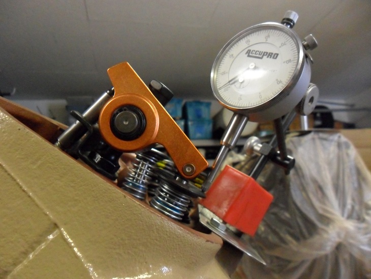

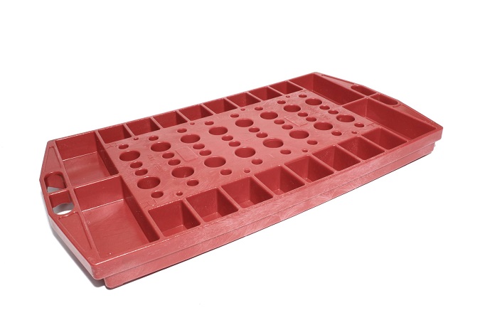
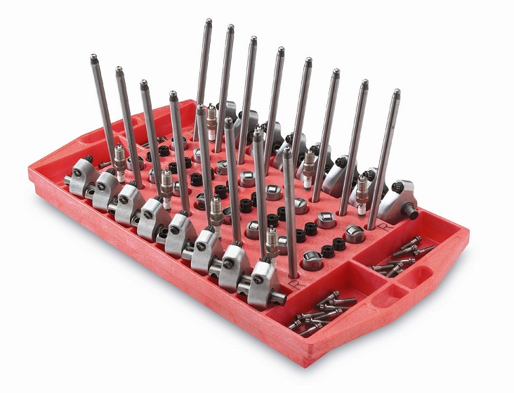
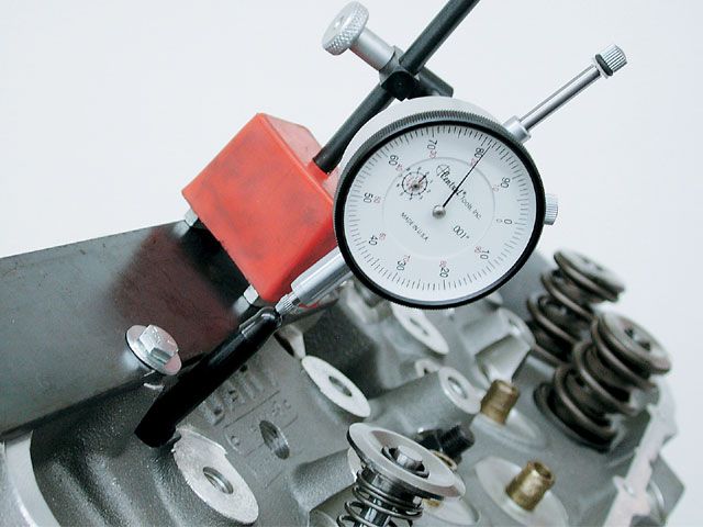
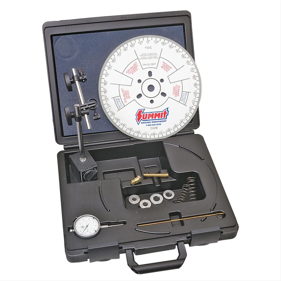
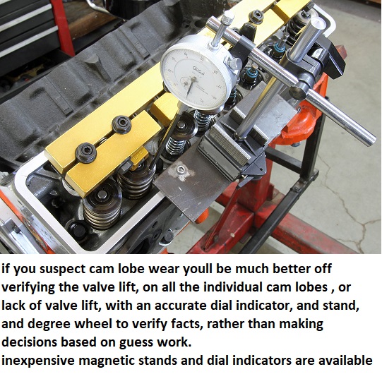
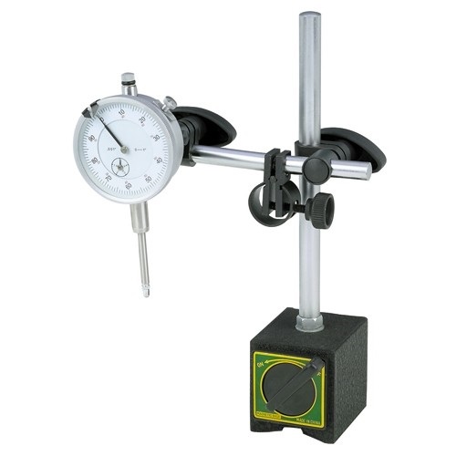
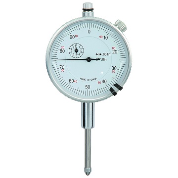
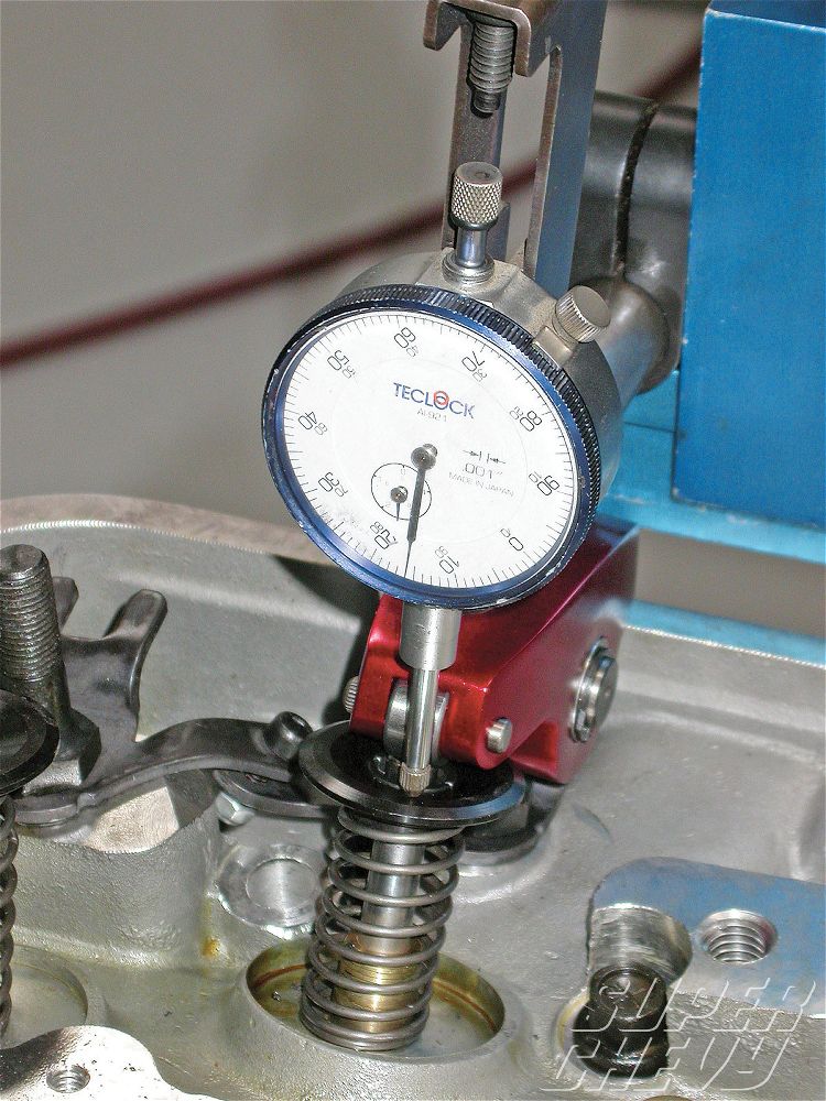
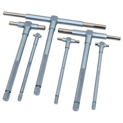
almost every mechanics tool box needs a few basic measuring tools and supplies
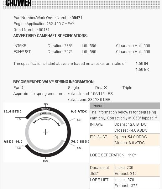
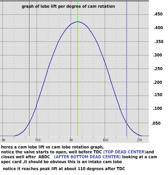
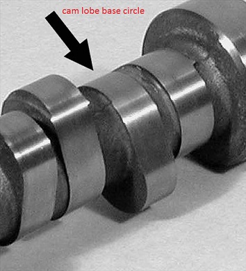
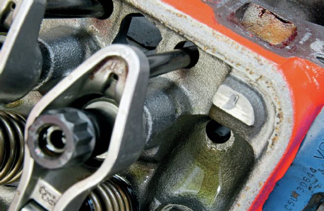
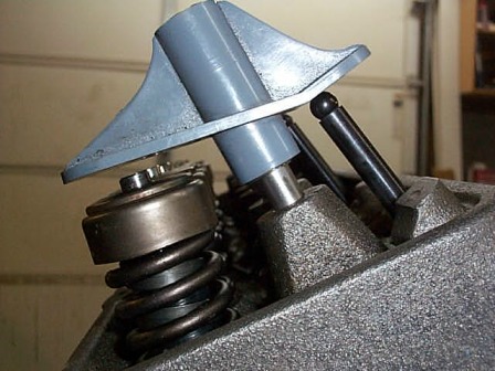
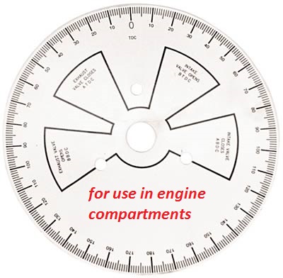
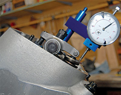
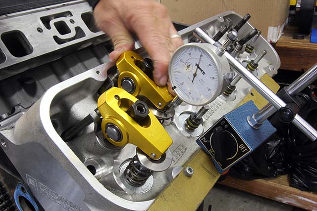
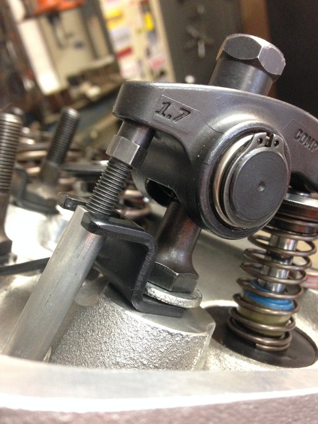
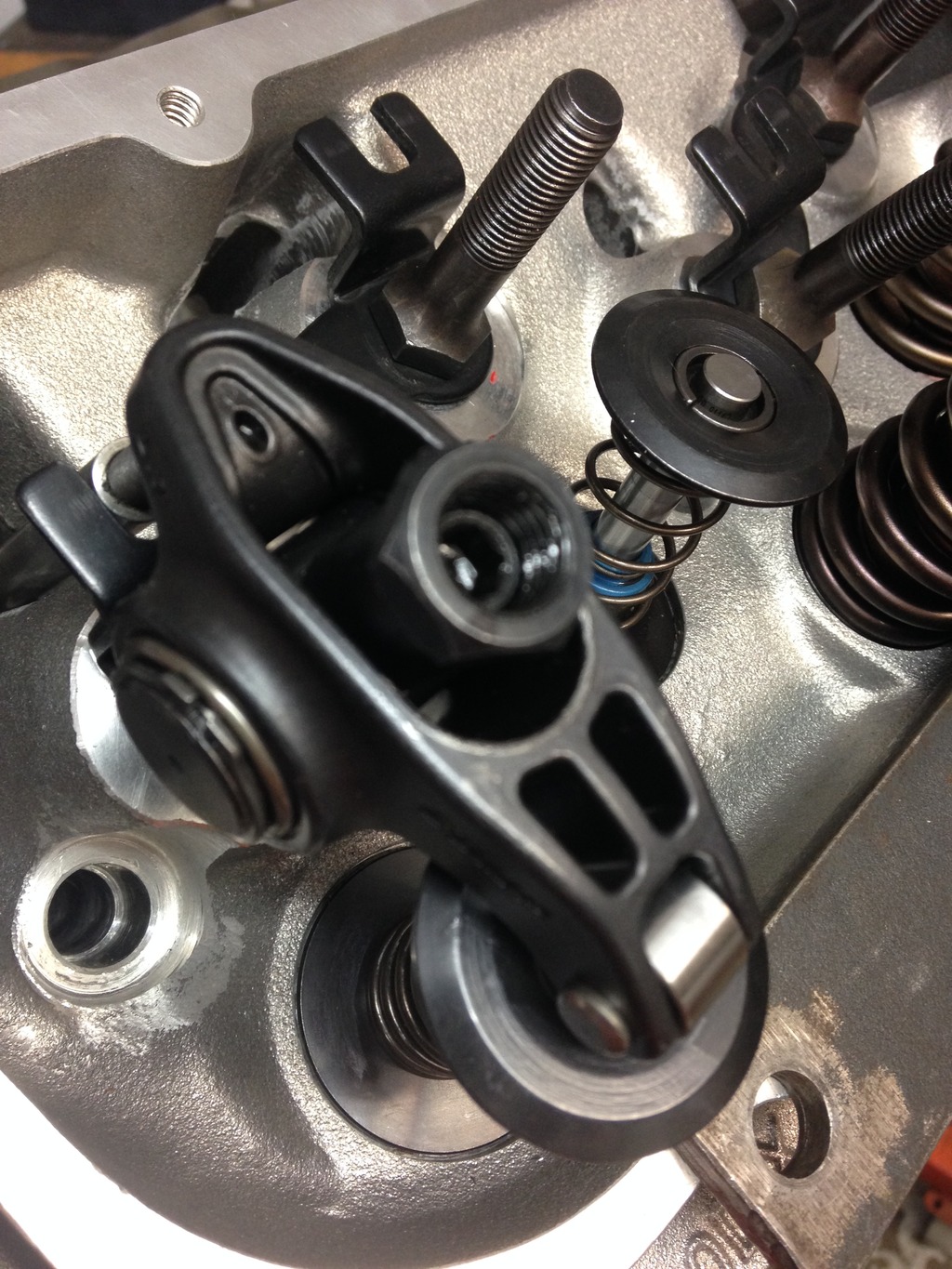
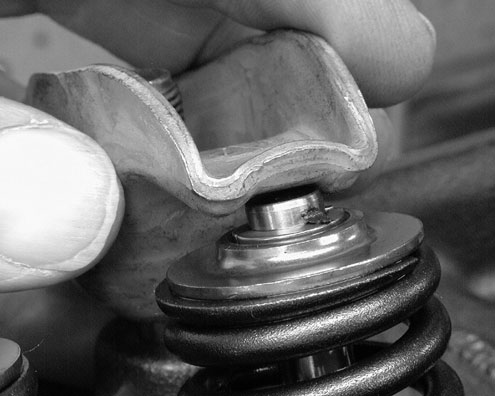
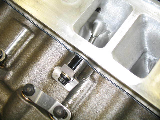
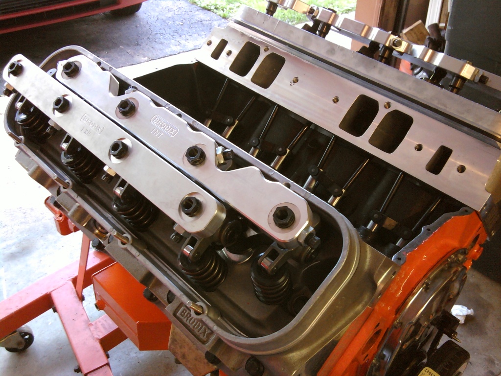
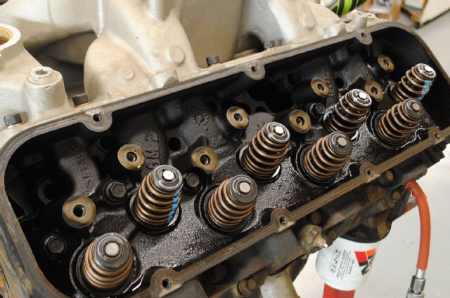
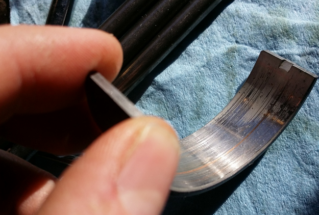
If you suspect a worn cam lobe, checking the cams lobe lift with a dial indicator on the valve spring retainer vs the other lobes would certainly provide useful related info.
knowing vs guessing helps in making decisions wisely
http://www.summitracing.com/parts/pro-66830/overview/
https://www.harborfreight.com/multipositional-magnetic-base-with-fine-adjustment-5645.html
https://www.harborfreight.com/catalogsearch/result/index/?dir=asc&order=EAScore,f,EAFeatured+Weight,f,Sale+Rank,f&q=indicator+stand
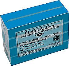 https://www.amazon.com/Claytoon-Set...d=1466872286&sr=8-17&keywords=plastilina+clay
http://www.utrechtart.com/Plastalin...currency=USD&gclid=CN3G75zOw80CFQgaaQodKbgFjA
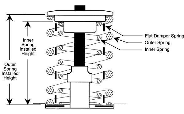
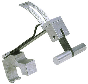
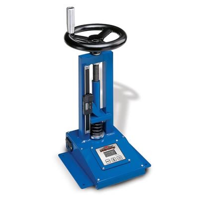
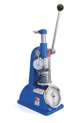
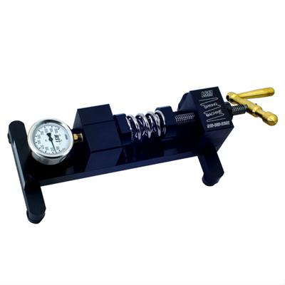
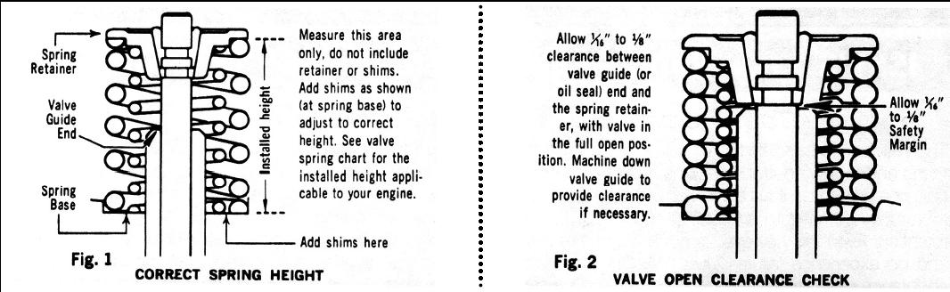
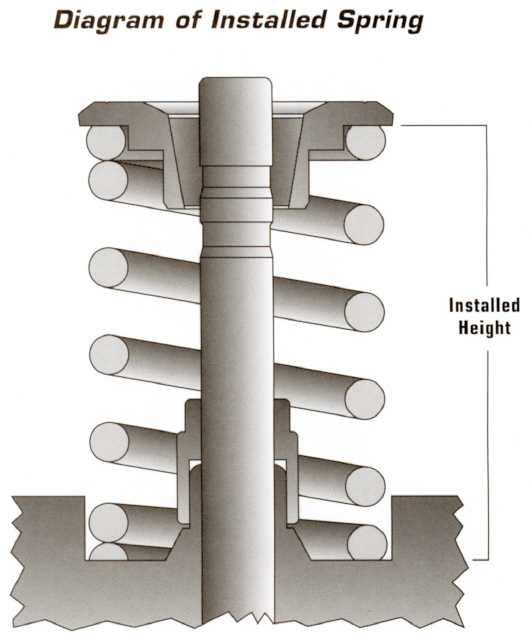
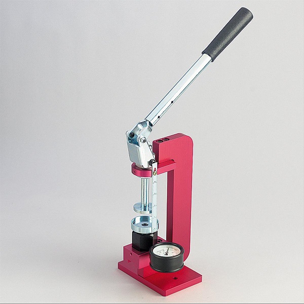
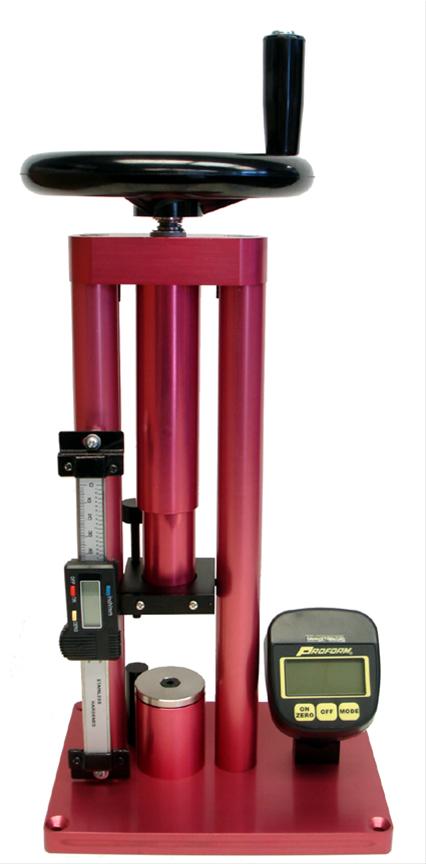
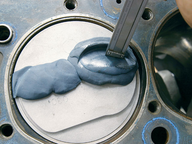
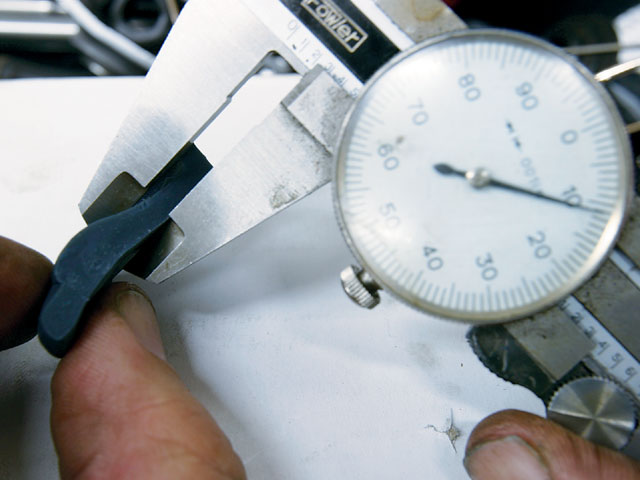
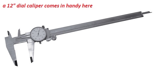
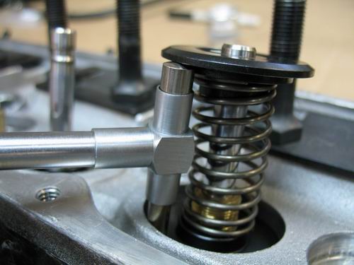
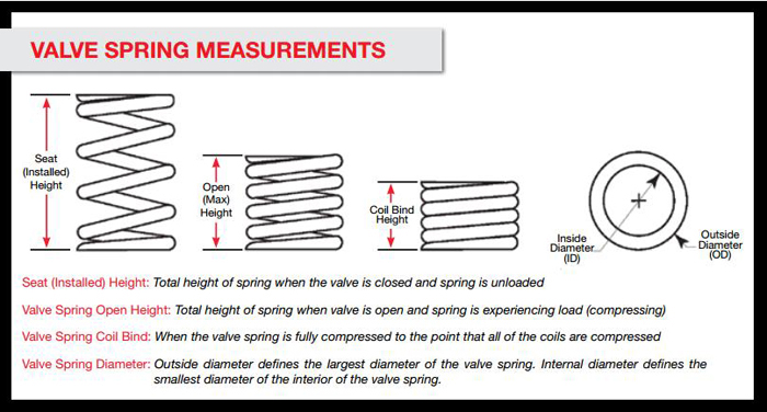
When checking valve spring installed height and valve clearances you can,t guess,.its mandatory you don,t guess and actually measure clearances, valve spring micrometers are not expensive and owning or borrowing one for your engine assembly makes a good deal of sense, you can get close with SNAP GAUGES, and a 2" standard micrometer or a vernier caliper, while valve springs won't increase lift, (thats dependent on cam lobe and the rocker ratio) the proper combo of shims, retainers, valve springs, and keepers and in some cases longer valves can effectively increase valve train clearance
all turbo and super charged engines, bring into play an additional factor when you set up your engines valve train, and select valve springs.
you might want to change too or select better and upgraded valve springs simply because a boosted or supercharged engine obviously has pressure in the intake runners and what most guys fail to understand is that that means theres about 3.2 square inches of intake valve and if theres 10 lbs of boost the result is it requires about 30 lbs more effective spring seat pressure to firmly seat the valve on its seat at higher rpms,add the fact that valve springs lose tension over time bue to heat and constant stress and your 100% sure to see a loss of consistent valve train component control, at a lower rpm than the identical cam used without boost, with identical spring installed height and seat and full lift load numbers.
if youve ever stuck your thumb over a garden hose trying to stop the water flow youll realise that sealing it against flow requires a good deal of force
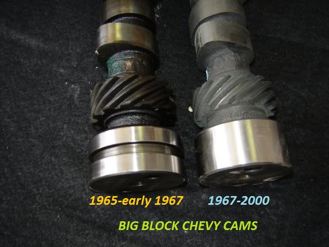
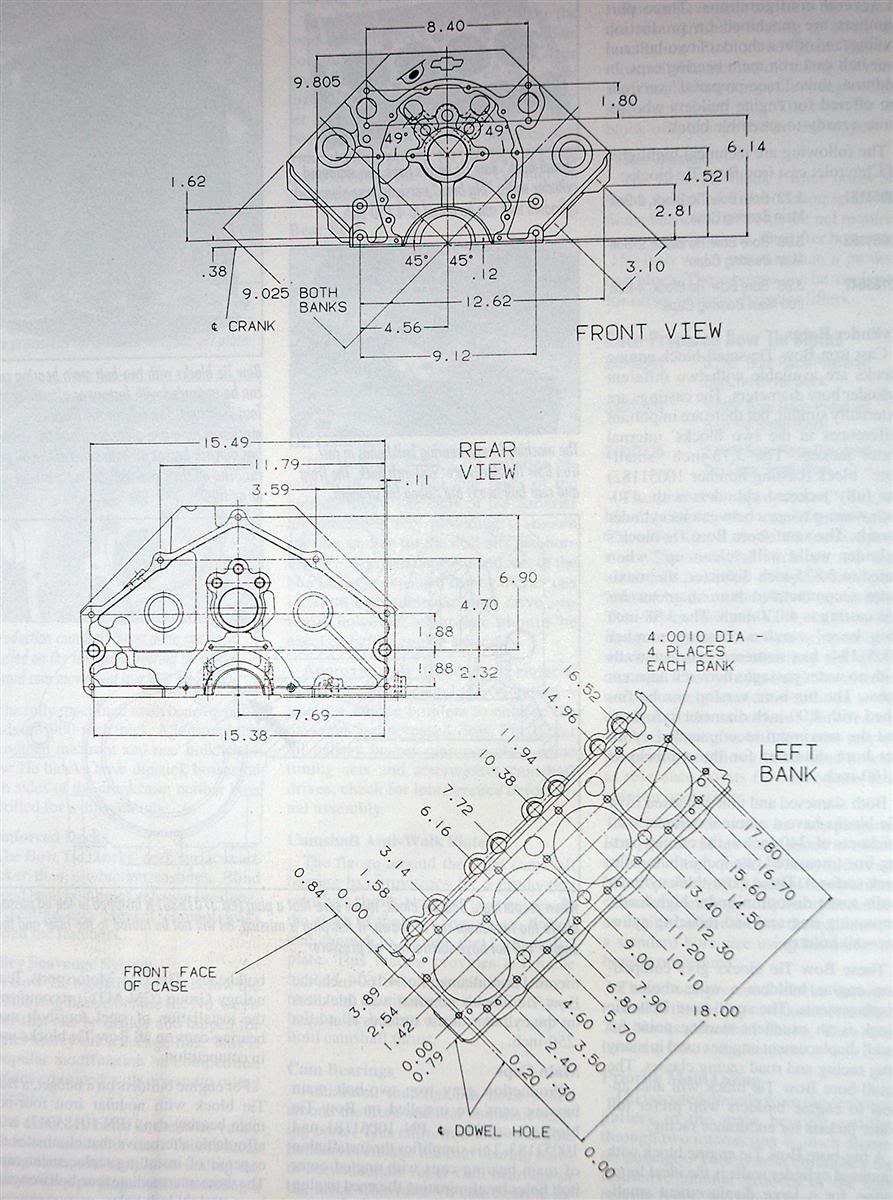
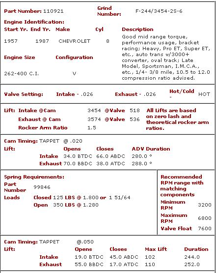
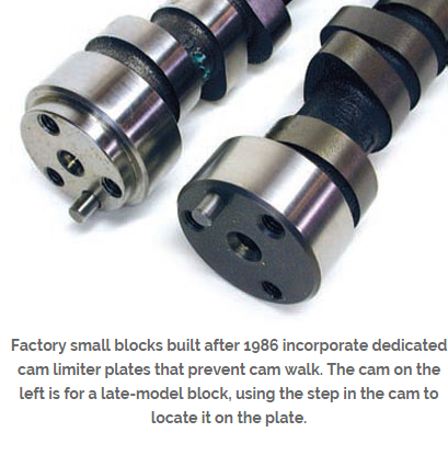
If your ordering any cam, be very sure you explain what year block and what cylinder heads will be used as there are differences in the cams. between early and later SBC, block s and the cams they require,and on big blocks theres similar issues, a mark VI cam is different from a MARK IV cam
http://www.grumpysperformance.com/flowridge1.png[\img]
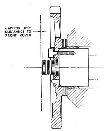
any time you change cams youll need to use a matching distributor gear, the cam manufacturer should be able to help tell you what matches, obviously checking clearances helps
and dipping the gear in moly assembly lube before it installed helps
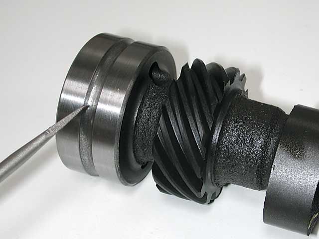
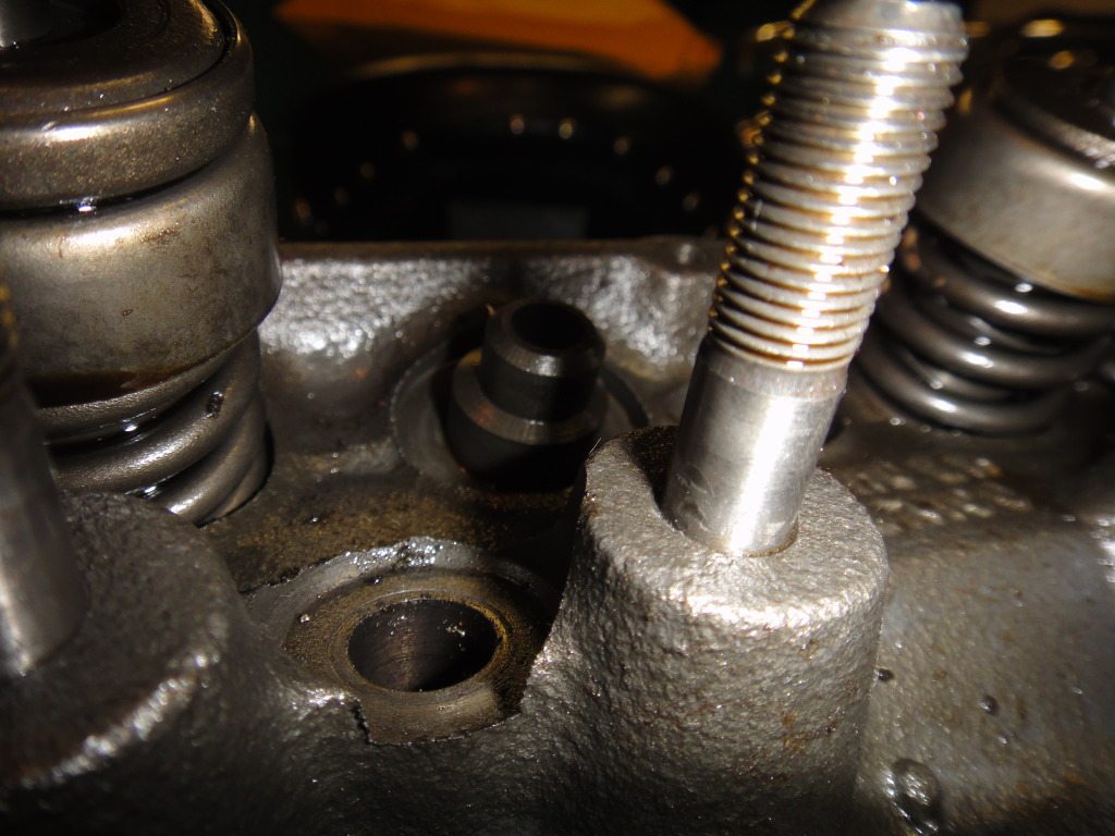
be sure you inspect the distributor gear for excessive wear
especially if you changed from a flat tappet to a roller cam.
if your seeing the timing change a few degrees, back and forth,
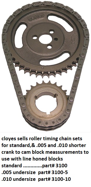
slack in a worn, loose timing chain, worn distributor gear or not having the proper shim clearance on the distributor center shaft will provide slop that allows timing to vary several degrees
http://www.kmotion.biz/instht.htm


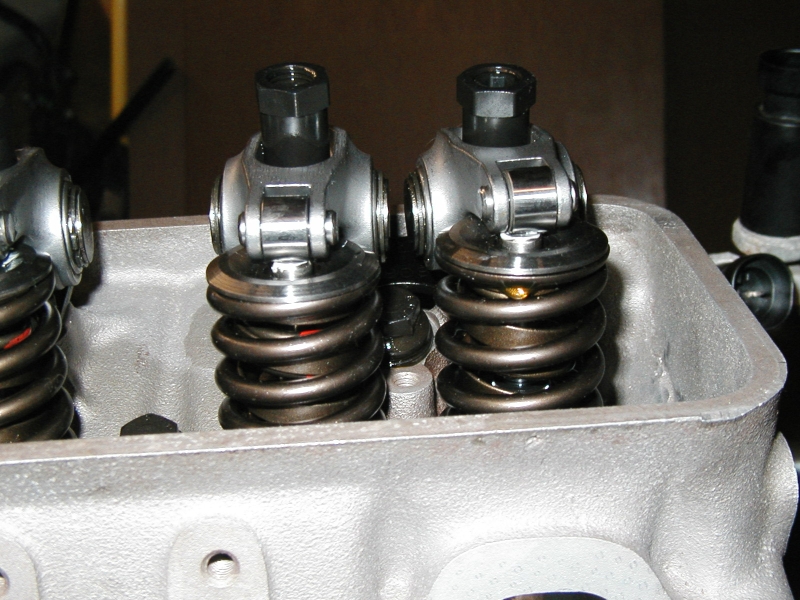
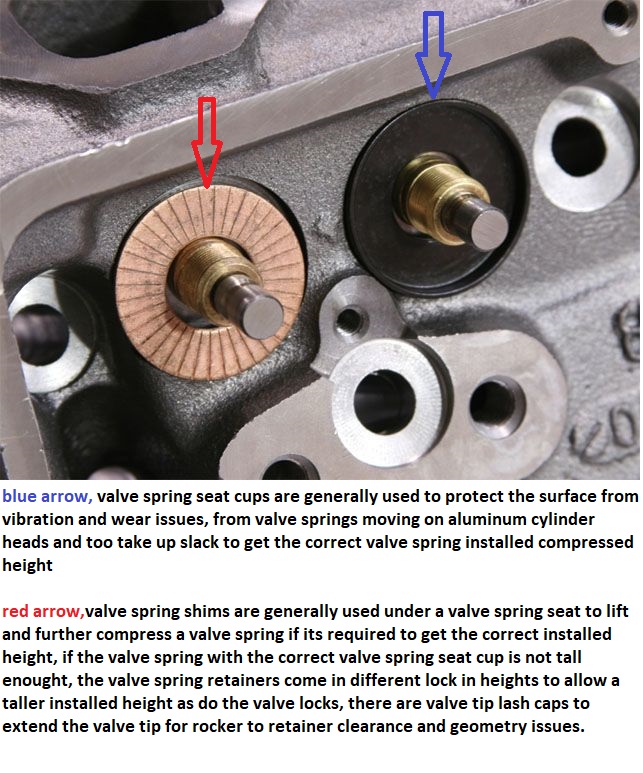
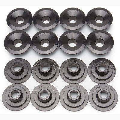
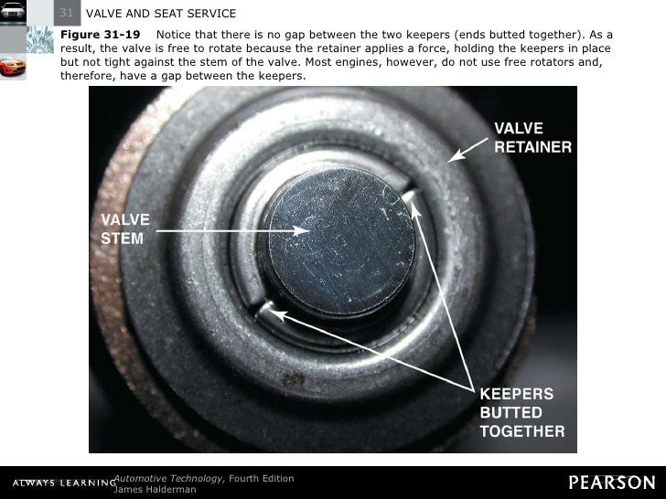
there are PLUS .050, standard and NEG .050 height retainers and valve cups and shims to adjust the installed valve spring height and location in regard to the cylinder head and valve guides
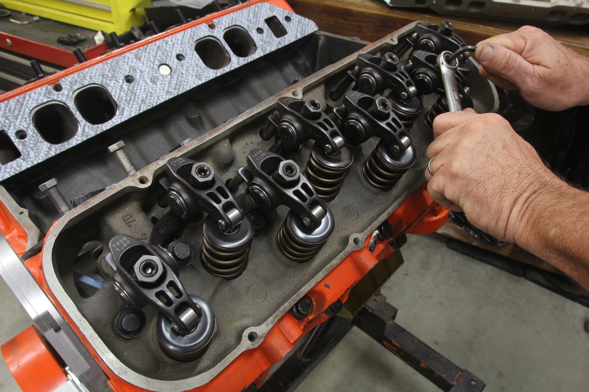
If the valve springs are to be removed with the heads still on the car,
the last thing you want is too remove a valve spring and have the valve to drop into the cylinder,
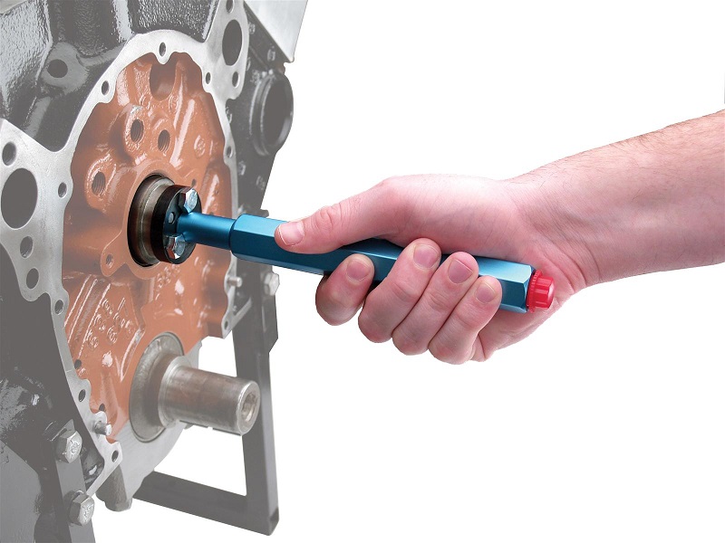
if you use air the crank tends to want to spin the crank to BDC, youll want to verify TDC ,
and make sure the flywheels temporarily prevented from turning from that the TDC position,
Ive used both methods both work,you can put 6 ft of rope in the cylinder while its in BDC then turn it to TDC, Ive used both with zero issues,
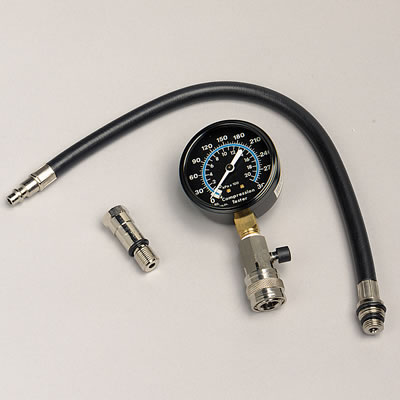
If you use the compressor youll want to keep it at 120 psi and constantly feeding pressurized air to keep the valves held in place,
and theres a small chance the compressor pushes enough moisture to allow water to accumulate in the cylinders,
so be sure you spin the engine with the starter with the spark plugs removed several times before you re-install plugs.
if you use the rope, theres a very low chance that the rope will tangle and form a knot that makes removal difficult
http://www.lunatipower.com/Tech/Valvetrain/HowToVerifyValvetrainGeometry.aspx
http://garage.grumpysperformance.co...alves-and-polishing-combustion-chambers.2630/
http://garage.grumpysperformance.co...ck-chevy-gen-v-vi-to-adjustable-rockers.4564/
http://www.summitracing.com/search/...d-length-checkers?autoview=SKU&ibanner=SREPD5
Proform Pushrod Length Checkers 66789 SBC 3/8" rocker studs
Proform Pushrod Length Checkers 66790 SBC 7/16" rocker studs
Proform Pushrod Length Checkers 66806 BBC 7/16" rocker studs
***
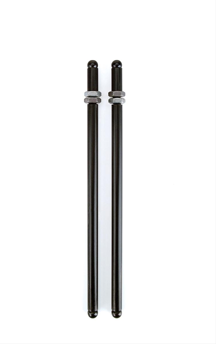
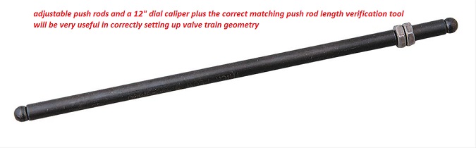
heres a bit of useful related push rod length info
Big Block Chevy, Standard Length Big Block Intake 3/8" / .080" 8.275"
295-7941-8 Big Block Chevy, Standard Length Big Block Exhaust 3/8" / .080" 9.250"
295-7969-8 Big Block Chevy, Standard Big Block +.100" Long Intake 3/8" / .080" 8.375"
295-7979-8 Big Block Chevy, Standard Big Block +.100" Long Exhaust 3/8" / .080" 9.350"
295-7951-8 Big Block Chevy, Standard Length Big Block Tall Deck Intake 3/8" / .080" 8.675"
295-7961-8 Big Block Chevy, Standard Length Big Block Tall Deck Exhaust 3/8" / .080" 9.650"
295-7800 V8 396-454 Retro Fit Pushrod Set, Intake & Exhaust, 1965-Present
3/8" / .080"
3/8" / .080" 7.725 Int.
8.675 Exh
295-7913-16 Small Block Chevy, Standard Length Small Block Chevy 3/8" / .080" 7.800"
295-7984-16 Small Block Chevy, +.100" Long 3/8" / .080" 7.900"
295-7934-16 Big Block Ford, Standard Length Ford `72-'78 429-460 3/8" / .080" 8.550"
295-7951-16 Big Block Ford, Standard Length Ford `69-'71 429-460 3/8" / .080" 8.675"
295-7582-16 Oldsmobile, Std Length 455 5/16" 9.550"
http://www.racingsprings.com/
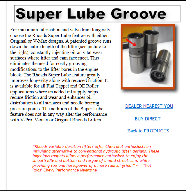
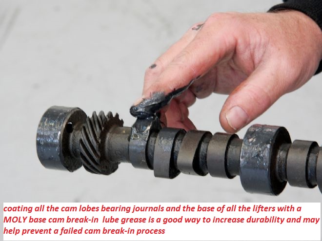
preventing cam & lifter break-in failures
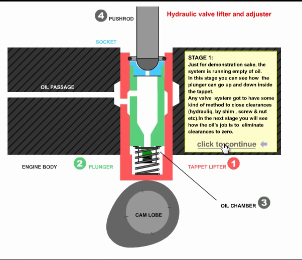
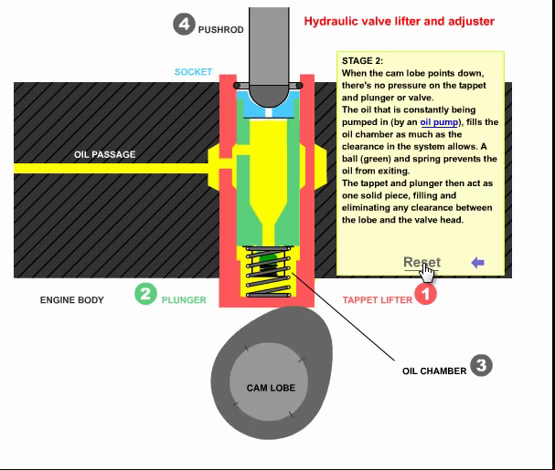
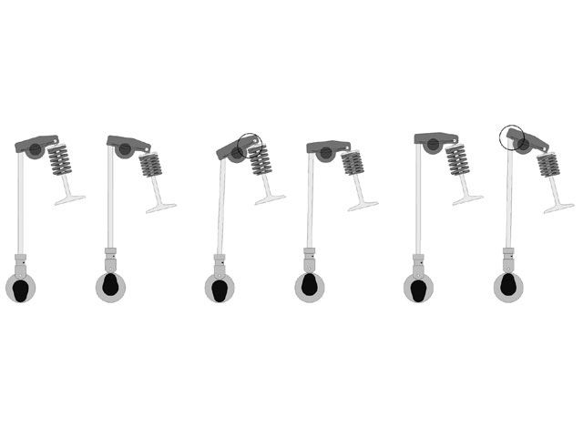
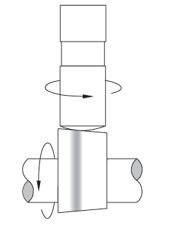
watch this video, it depicts the lifters movement as the cam lobe rotates under its base forcing it up as the lobes ramp, rotates under the lifter base,removing the clearance slack,
as it compresses the valve spring and forces the trapped oil, up the push rod and lifts the valve
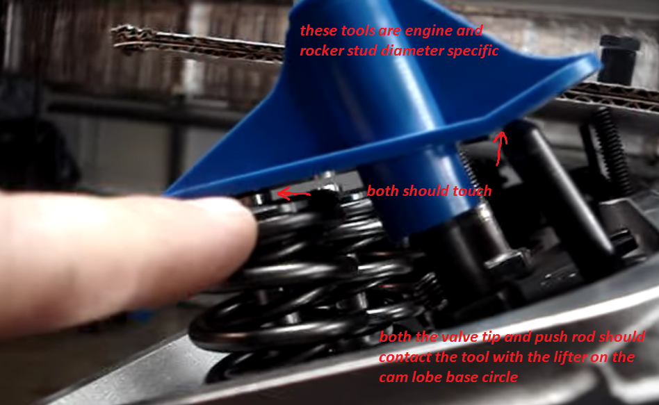
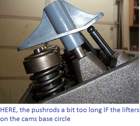
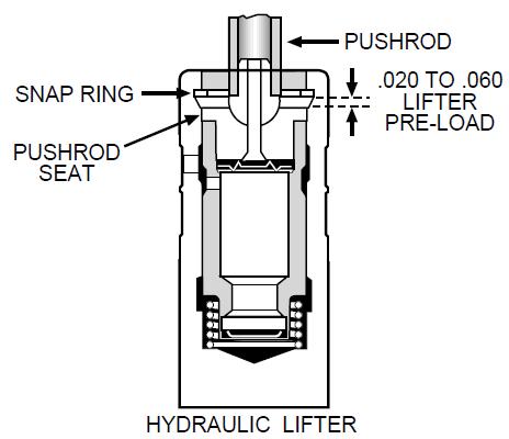
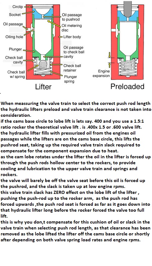
If you are concerned with measuring the clearance in the hydraulic lifter seat when selecting and measuring the correct valve train geometry,
so you can order the correct length push rods...
I don,t think you have the correct idea as to how hydraulic lifters work,
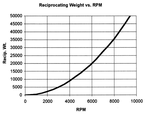
yes it is possible for an engine with hydraulic lifters to be pushed too operate at a high enough rpm that the time required for the lifter seat to fully depress and all the oil too be forced up to the push rod/rockers , to be so short that the lifter pumps up and the valves will have less seat time, ( sometimes one of several factors, like the lifter leaving the cam lobes surface as the inertial loads exceed the valve springs ability to maintain lifter too lobe contact, referred too or contributing to what is commonly referred too as valve float) but that has ZERO to do with selecting push rod length or proper valve train geometry, (remember at 6000 rpm the valve is lifted off its seat 50 times PER SECOND)
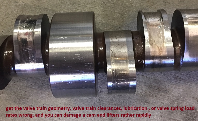
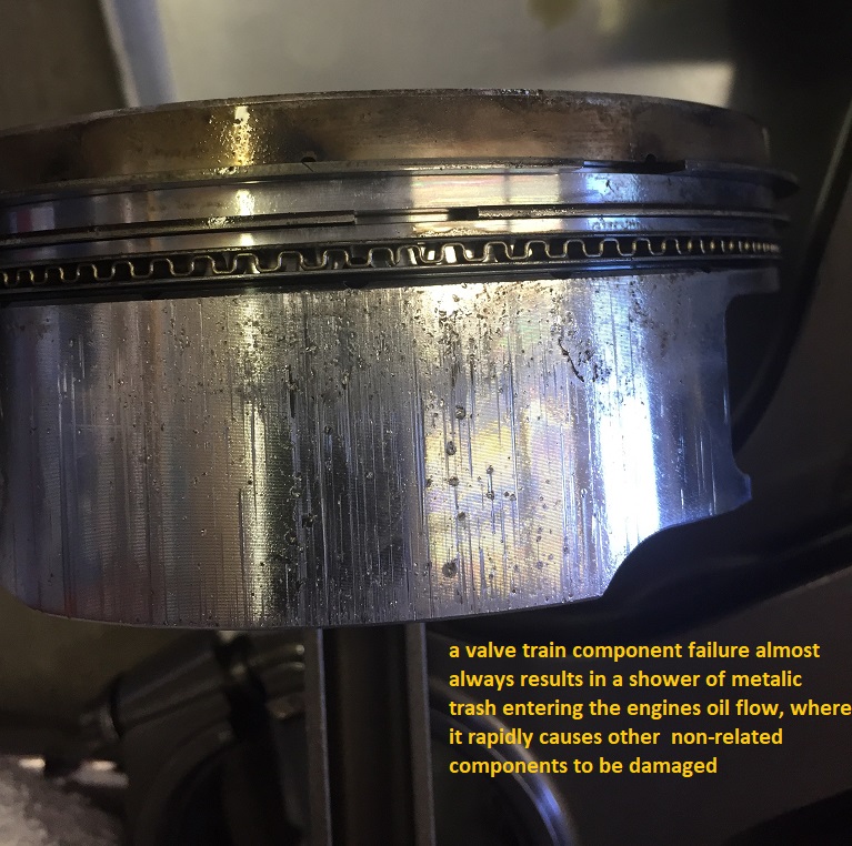
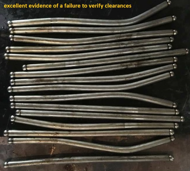
it only takes a few seconds running a new engine for an improperly installed cam , lifters and valve train, during the break-in process to generate teaspoons of metallic trash that ,once in the engine oil flow ,rapidly destroys bearings if the clearances ,spring load rates or valve train geometry is wrong
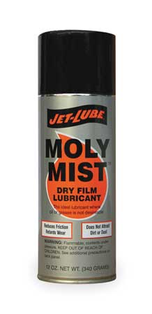
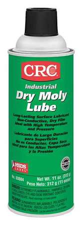
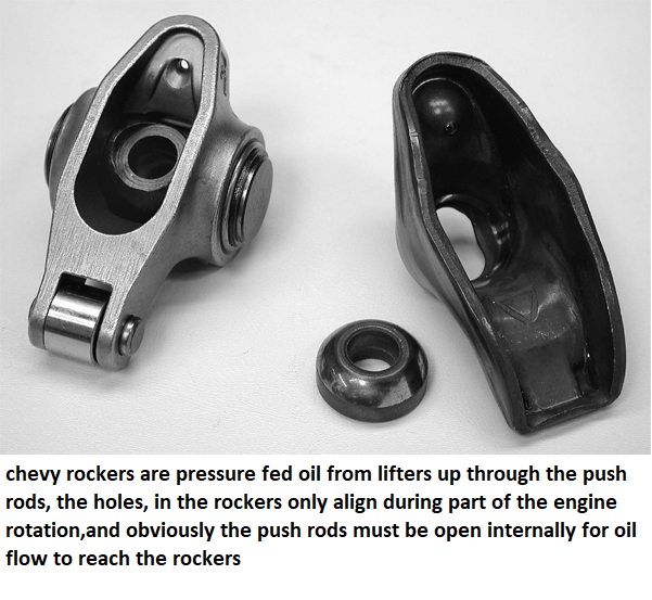
it should be rather obvious that there's options,you'll chose in both valve train components and lubricants, cam failures are usually the result of incorrect CLEARANCES or too much SPRING PRESSURE or LACK of ADEQUATE LUBRICATION,USE DECENT MOLY CAM LUBE, and decent quality oil, adding MAGNETS to trap metallic CRUD HELPS, if your not getting constant oil flow from each rocker /push rod at idle theres something wrong and that needs to be checked
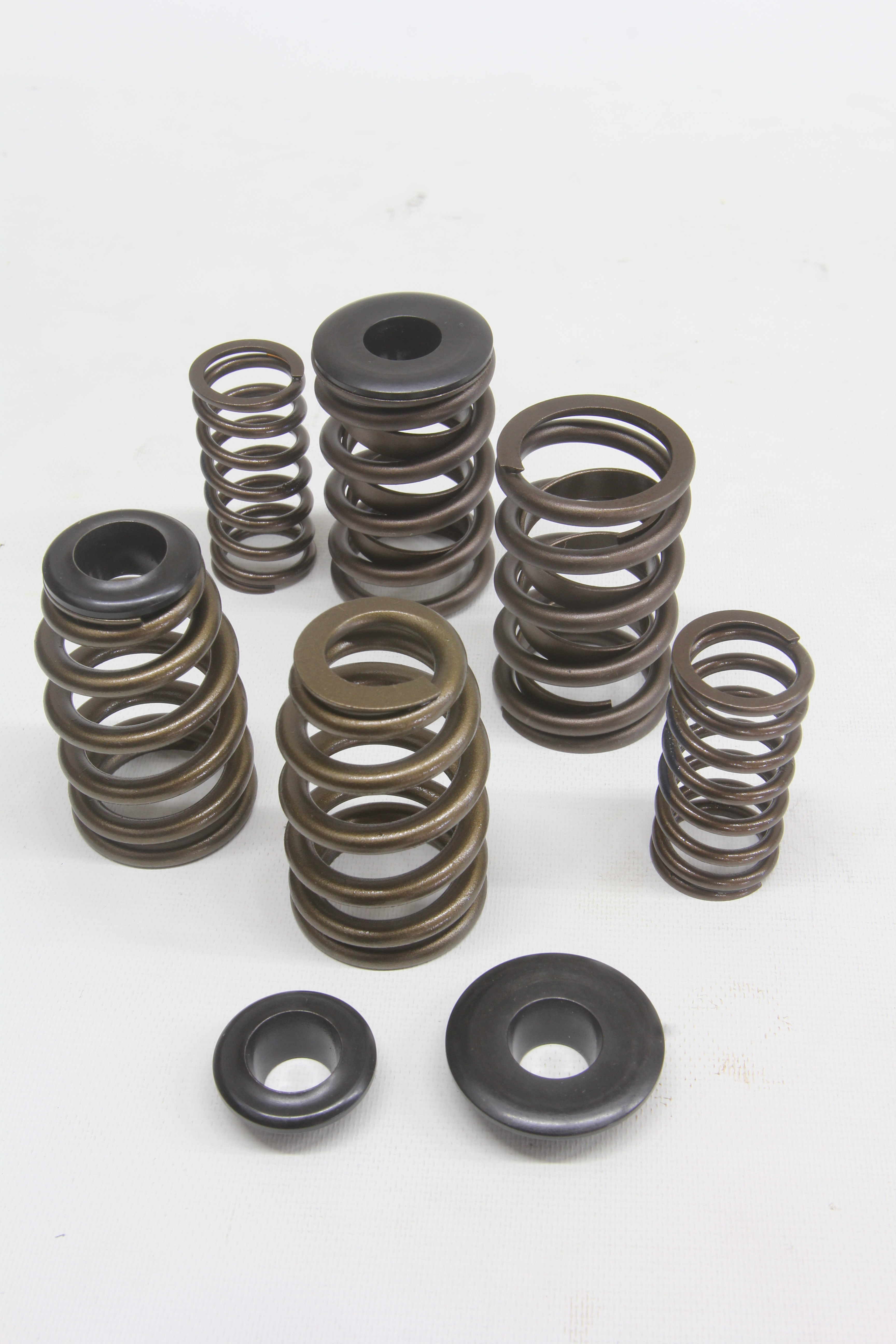
yeah! as I stated it varies with engine cam used and application,yes BBC valve springs tend to be larger as the valves weigh more, but generally theres not a huge amount of compression during the install and obviously the cam generally comes with the installed height, valve spring part numbers and intended load rates that should be used, and yes you still need to use shims, valve spring cups and watch out that at max lift you still maintain the required clearances


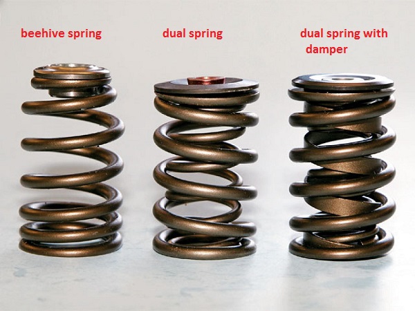
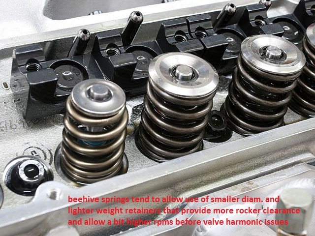
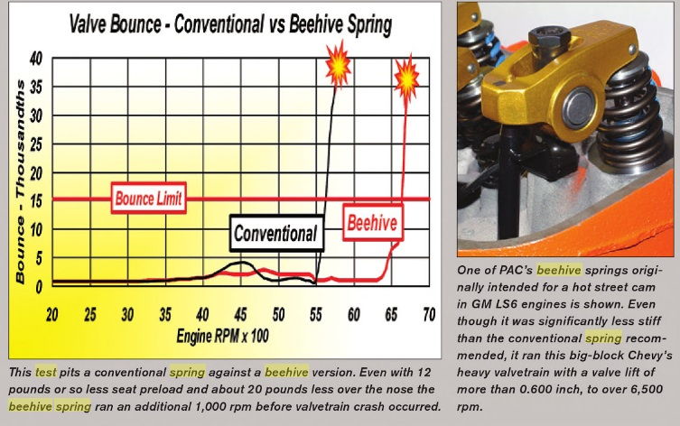
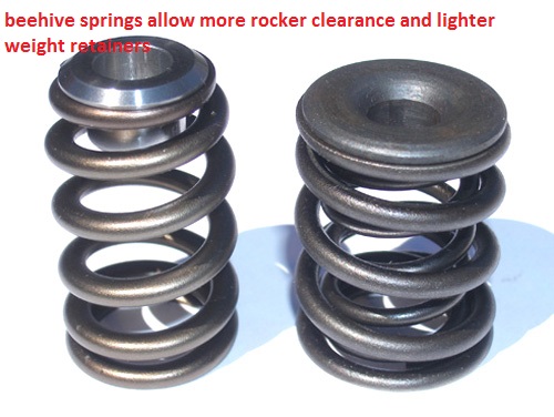

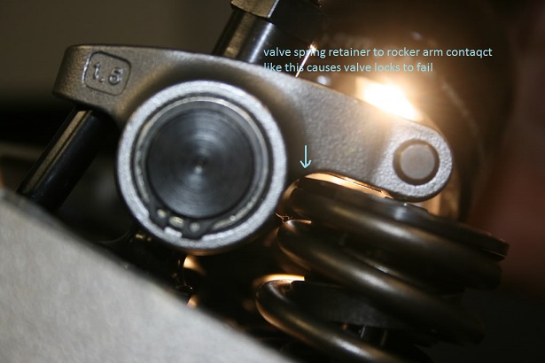
BEEHIVE SPRINGS GIVE A GOOD DEAL MORE ROCKER TO RETAINER CLEARANCE
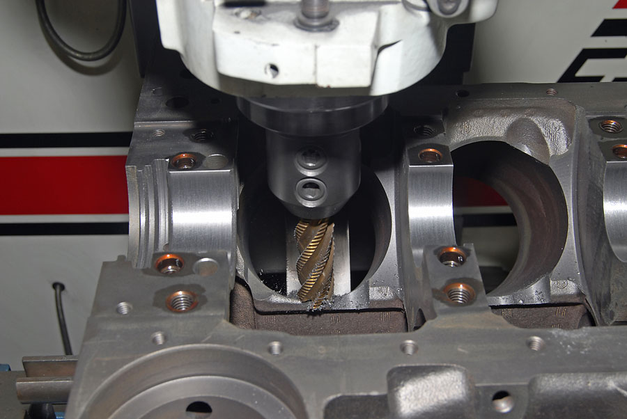
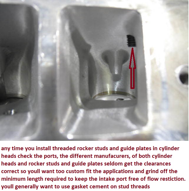
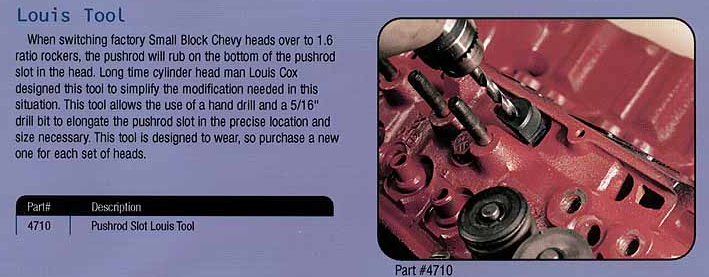
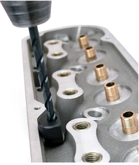
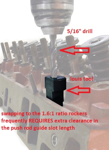
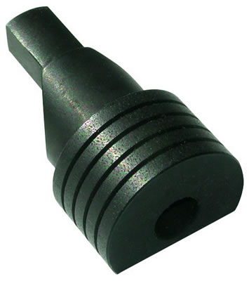
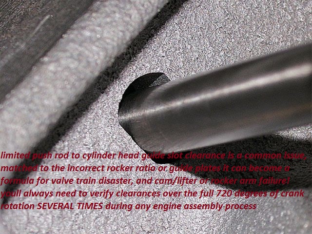
if you change the rocker ratio the push rod alignment changes and you might need a LUIS TOOL to lengthen the cylinder head clearance slots in the cylinder heads.
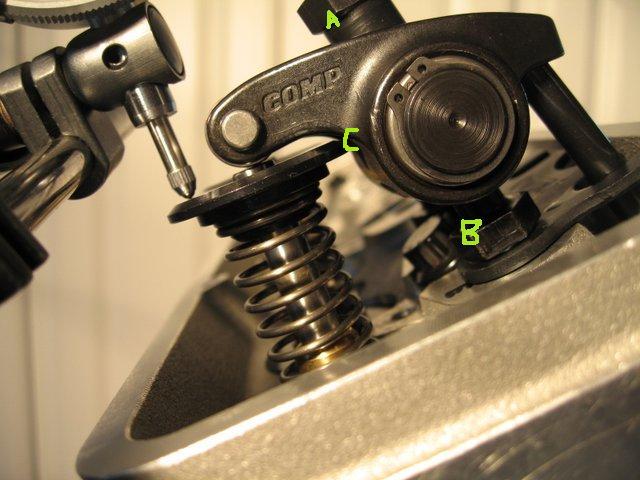
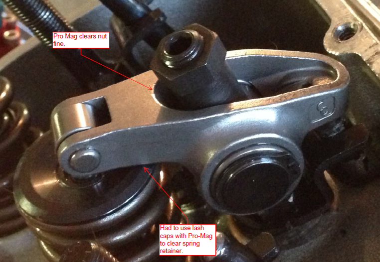
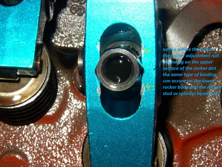
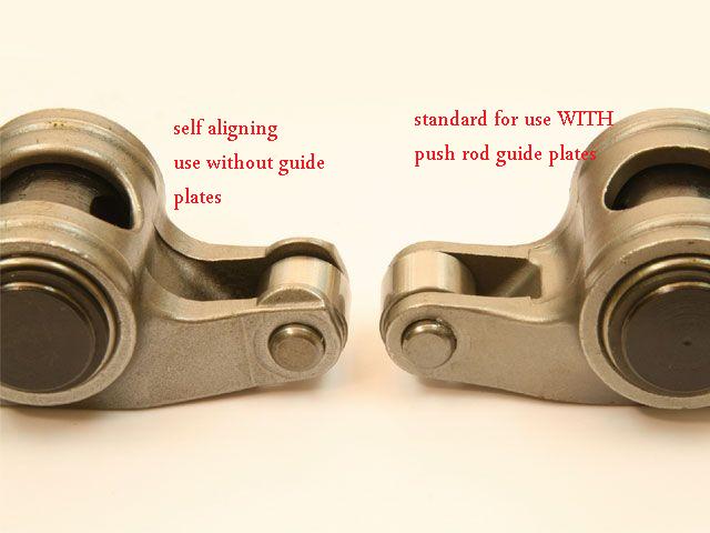
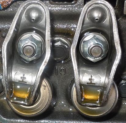
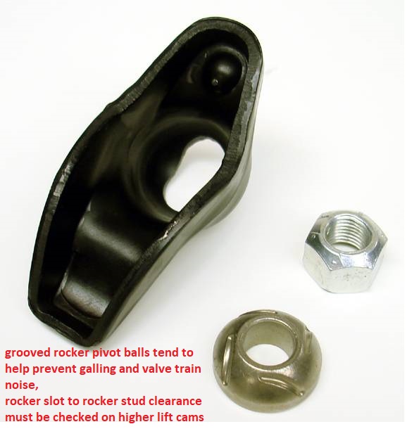
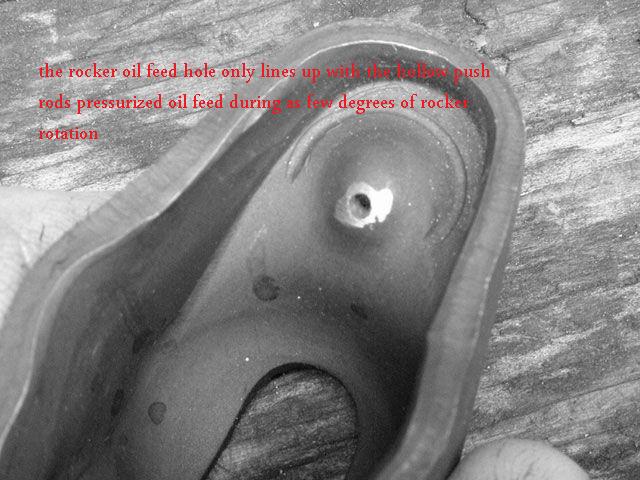
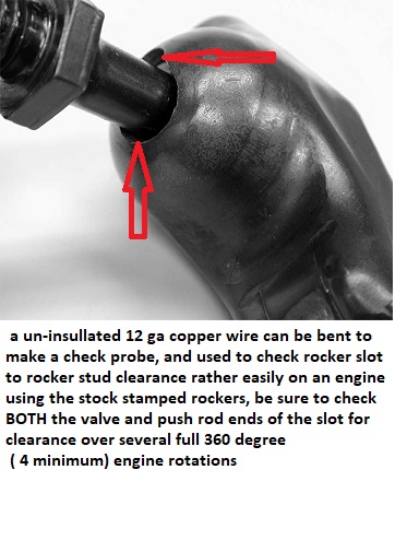
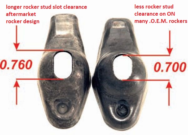
be sure to check clearances carefully like coil bind,and push-rod to guide plate alignment and clearances ,verify the rocker slots don,t bind on the rocker studs as this is a common problem with stock stamped style 1.6:1 ratio rocker, verify the push rods don,t bind in the slots in the cylinder head, if they do even for an instant at one point in the rockers arc, they can bind the lifter rotation on the cam lobe and cause the cam to wipe, out the lobe and the lobe & lifter contact area resulting in a quickly failed cam,and/or restrict oil to the rockerss

check all valve train geometry and clearance on any engine you assemble or modify the valve train on.
READ
http://rehermorrison.com/tech-talk-86-spin-and-win-evaluating-valvetrains-the-old-fashioned-way/
http://www.hotrod.com/techarticles/engi ... index.html
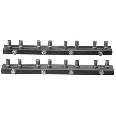
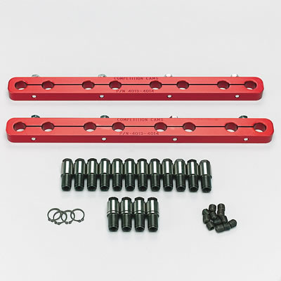
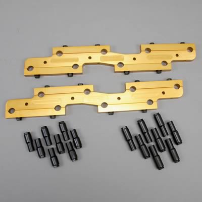
these adjustable push rod guide plates come in handy at times

(1) get a decent ROLLER CAM, add a high volume oil pump, baffled 8 qt oil pan, with a windage screen and check your clearances and avoid the problem,USE DECENT MOLY CAM LUBE,and decent quality oil,adding MAGNETS to trap metallic CRUD HELPS
(2) use a SOLID lifter flat tappet cam with lifters with the lube feed holes,add a high volume oil pump, baffled 8 qt oil pan, with a windage screen and check your clearances and avoid the problem,USE DECENT MOLY CAM LUBE, and decent quality oil,adding MAGNETS to trap metallic CRUD HELPS
http://www.competitionproducts.com/prodinfo.asp?number=651080DL
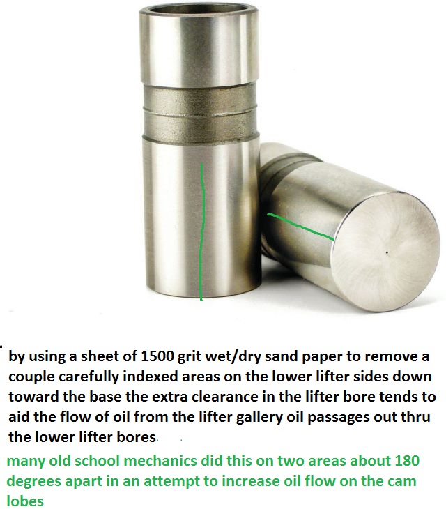
(3) mod the lifter bores for more oil flow,add a high volume oil pump, baffled 8 qt oil pan, with a windage screen and check your clearances and avoid the problem,USE DECENT MOLY CAM LUBE,and decent quality oil,adding MAGNETS to trap metallic CRUD HELPS
http://www.compperformancegroupstores.c ... gory_Code=
(4)USE DECENT MOLY CAM LUBE
http://www.cranecams.com/index.php?show ... l=2&prt=15 ,
add a high voluum oil pump, baffled 8 qt oil pan, with a windage screen and check your clearances and avoid the problem,and decent quality oil,adding MAGNETS to trap metalic CRUD HELPS
(5) thinking things thru and verifying clearances and spring pressures, and having a well thought thru lube system will significantly lower your chances of having problems,USE DECENT MOLY CAM LUBE,and decent quality oil,adding MAGNETS to trap metallic CRUD HELPS
.......I have not seen a cam fail in years UNLESS the guy installing it failed to follow those tips
https://www.ebay.com/i/402584062207...1291&msclkid=d17e7155654a1a20769a115a09f43c68
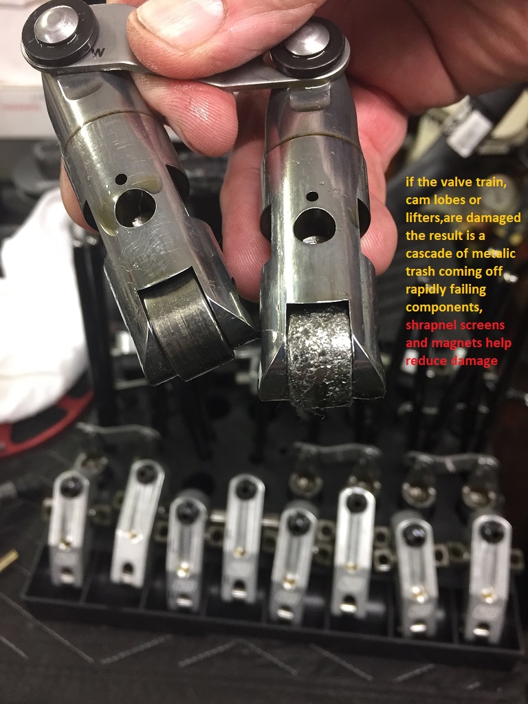
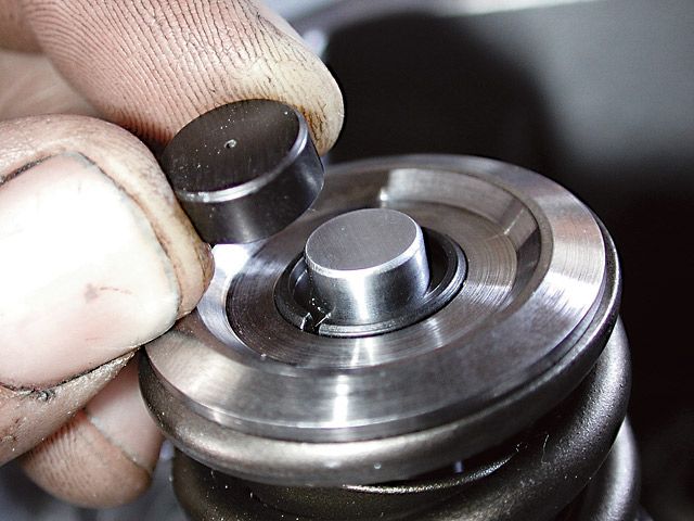
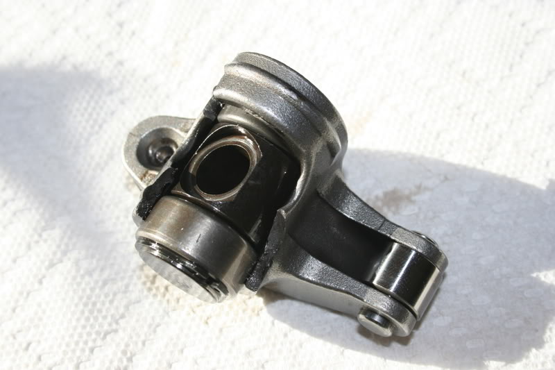
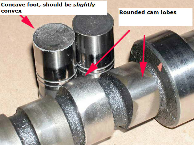
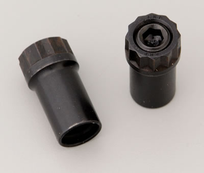
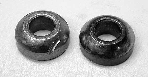
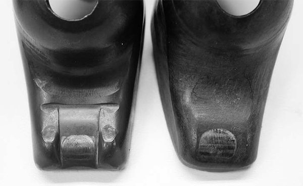
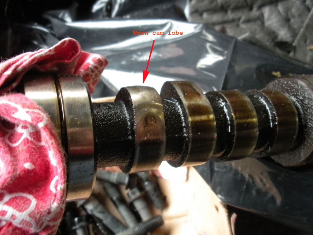
if the lifter base is well worn you can bet the farm the cam lobe is most likely also worn, and you'll need a lifter removal tool to pull the damage lifters up out through the blocks lifter bores

 The following recommendations are from Erson Cams.
If you have questions, you can reach their tech department at 800-641-7920.
most cam manufacturers do extensive testing with each engine design to verify the limits and limitations of each engines valve train design, so it generally helps to talk with the cam suppliers tech department engineers.
cam lobe acceleration / de-acceleration rates have a large effect on the required spring load rates, as do rocker ratios and cam lobe size and lifter diameters.
Hydraulic Flat Tappet Camshaft: 110 lbs Seat pressure/250-280 lbs open pressure
Solid Flat Tappet Camshaft: 130 lbs Seat Pressure/300-325 lbs open pressure
Hydraulic Roller Camshaft: 130-140 lbs Seat Pressure/300- 355 lbs open pressure
Solid Roller Camshaft: (Minimum Safe Pressures DEPEND ON SEVERAL FACTORS)
Up to .600Ë valve lift: 200-235 lbs Seat Pressure/600 lbs open pressure
Over .600Ë valve lift: 250-280 lbs Seat pressure /100 lbs pressure for every .100Ë of valve lift
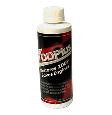
many more modern oil formulations lack the correct additives for flat tappet lifters, so be very sure you check to see what oil your using and if its designed for flat tappet lifter applications
Id also point out that youll want to lubricate any valve you install in a valve guide and verify the valve train clearances very carefully, and use the correct valve springs and add the correct valve seals installed
anyone see a PATTERN?
http://garage.grumpysperformance.com/index.php?threads/removing-valve-seals.4283/
you might want to read thru this AGAIN
http://www.highperformancepontiac.com/t ... index.html
http://www.cranecams.com/?show=article&id=2]http://www.cranecams.com/?show=article&id=2
FROM MORTEC
If you are building a SMALL or BIG block Chevy with a flat tappet cam, (solid or hydraulic lifters) be careful during the initial engine break in. It is very easy to lose a cam lobe and lifter during initial break in. This is especially true with a higher than stock lift cam and higher pressure valve springs. The increased push rod angles found on the BBC and poor preparation can make cam lobe failure after initial fire up a distinct possibility. You can help prevent this cam lobe failure by making sure the engine is pre-lubed prior to initial fire up. Use a good high pressure lube on the cam lobes and lifter bottoms during assembly. If possible use a lighter pressure stock valve spring (or if using a valve spring with multiple springs, take out some of the inner springs) to initially run the engine. Then switch to the heavier pressure springs after break in. When the engine is first fired up, keep the engine rpms at 2,500 or above, don't let the engine idle for 20 minutes or longer. This keeps lots of oil splashing up on the cam lobes. Make sure the engine can be run for this time period by having enough fuel available, ignition timing set correctly, coolant available for the motor, valve lash set correctly, etc. The idea is not to crank the motor over excessively before it starts up for the first time. If your BBC flat tappet cam survives this initial break in period, it will be good to go for many miles. After the initial engine break in, drain the oil and change the oil filter. Roller cams generally do not suffer these types of cam lobe failures during initial engine fire up.
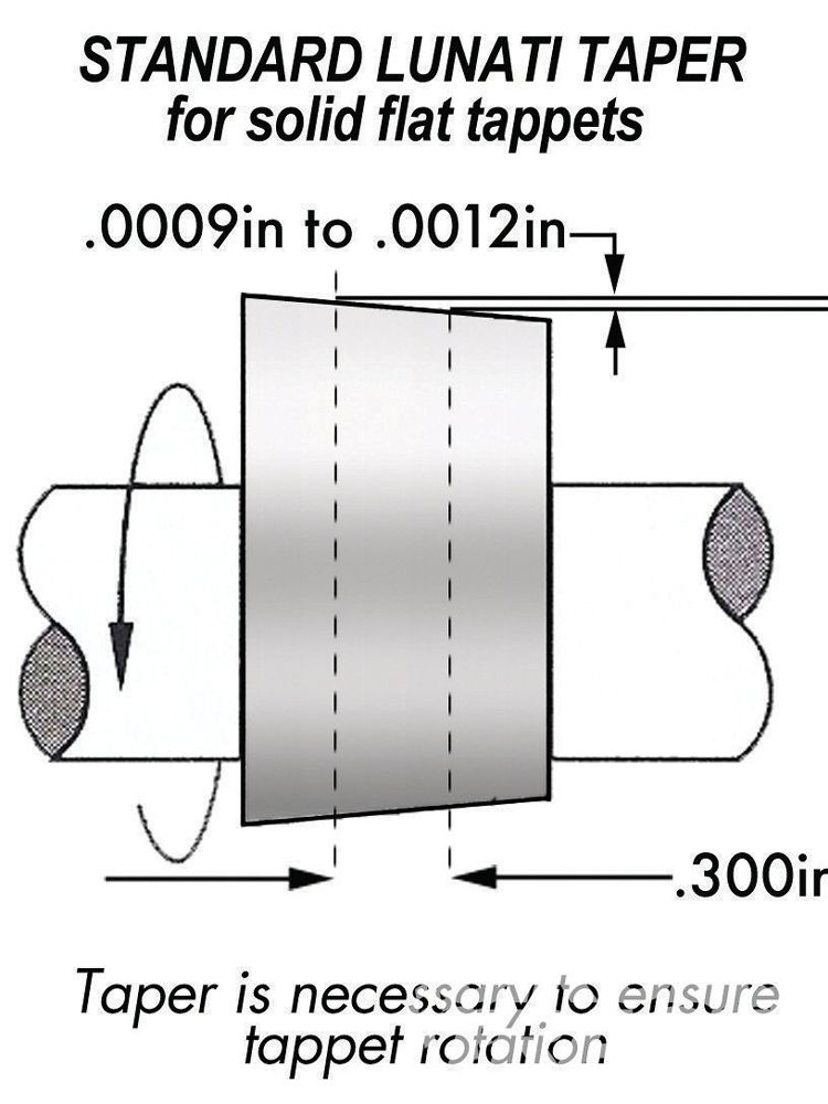
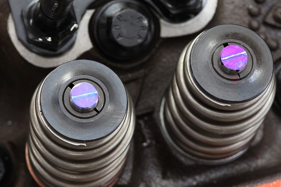
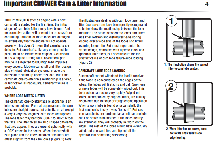
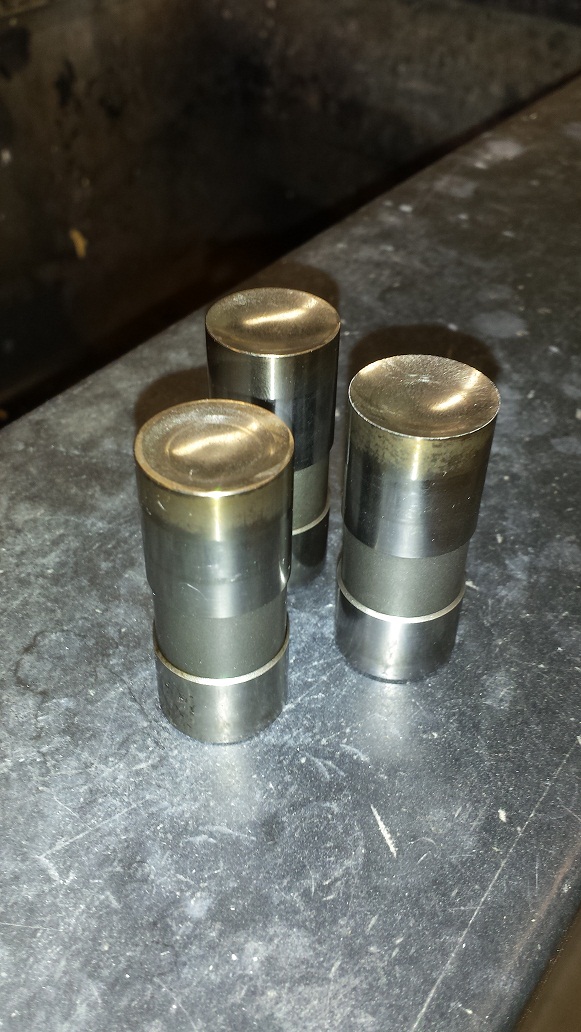
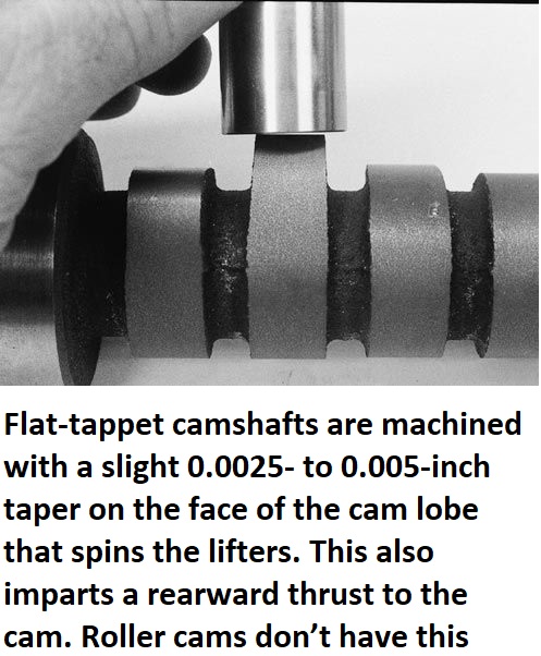
if you've adjusted the valves correctly the lifter spins at all rpm levels,but that does NOT mean it wears EVENLY at all rpm levels due to several factors if you look closely AT FLAT TAPPET CAMS you'll see that the center of the cam lobe is NOT centered under the lifter and that the lifter surface is slightly angled , BOTH these factors force the lifter to spin in its bore as the lobe passes under the lifter slightly off center.

SOME of the reasons the higher rpm durring the break in phase is important is that
(1) the faster RPMs the better chances the lobe passes under the lifter floated on an oil film and the less time the oil film has to squeeze out between them
(2) the higher the RPM the greater the oil volume and pressure the engine pumps and the more oil flow is available at the lobes
(3)the higher the rpm level the more oil is thrown from the rods onto the cam lobes
(4)the higher the rpm the greater the lifters weight and inertia tends to compensate for the springs pressure and lower the net pressure as the lifter passes over the cam lobes nose
(5) at higher rpm speed the better chance a small wedge of oil is trapped between the lifter base and lobe from the oil thrown from the lobes surface by centrifugal force
(6) two different metal surfaces scraping past each other at low speeds may tend to wear and GALL as the oil is squeezed out but two different hardness steel surfaces that impact each other at higher speeds covered with oil tend to work harden as they mate and will tend to be separated by that oil
(7)as the lifter spins in its bore the contact point between the lobe and lifter base constantly changes and rotates with the lobe contact point not resisting its passage and the higher the rpms the faster the lifter rotates and the less time the lobe spends at any one point
BTW ADD E.O.S. to the oil and MOLY break-in lube to the cam
before starting the engine and pre-fill the filter and pre-prime the oil system before starting the engine.
I normally pour it in just before starting the engines cam break in,procedure. because I want to make sure that nothing in the oil/E.O.S. mix can settle out from sitting over a long period of time. now if your running a flat tappet cam you should have also used a moly cam lube on the lobes and be useing a mineral base oil for the break-in procedure, and youll need to do an oil and filter change after about the first 3-4 hours running time to remove that moly cam lube from the engine after its served its purpose of protecting the cams lobes and lifters at start up, aND AS THE LOBES/LIFTERS LAPPED IN. MOSTLY to prevent that moly grease and E.O.S from potentially partially clogging the filter after that mix cools down,but also because both those lubes might leave deposits in the combustion chamber ,over time that might aggravate detonation.
even G.M. suggests that E.O.S. is not a great long term oil supplement, and that its main function is to add extra oil film strength durring new engine break in.
Isky claims that the Comp XE cams violate the 47.5% rule. The 47.5% rule applies to flat tappet cams for SBCs with 1.5 rockers but the concept is still the same for other configurations where the designs are "on the edge" or "over the edge" for lobe intensity. For 1.5 ratio SBCs, the duration at .050 must exceed 47.5% of the total valve lift or your asking valve train problems. For example, take a Comp Cams Magnum 280H, with 230 duration and, 480 lift...230/.480 = 47.9% which exceeds 47.5% therefore would not pose a threat to components. We do not regularly hear about the older, safer HE and Magnum designs rounding off lobes anywhere near as often as the XE cam designs. Unfortunately, some of the Comp Cams XE dual pattern lobes break this 47.5% rule on the intake side so they are likely to be problematic. The design has "steeper" ramps that are too quick for durability and reliability according to other cam manufacturers. They will wipe lobes in a heart beat especially if you have not followed the proper break-in procedure. Other designs are more forgiving during break-in and less likely to fail.
http://www.gmpartsdirect.com/results.cf ... number=EOS
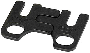
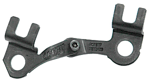
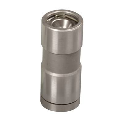
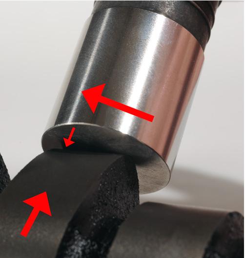
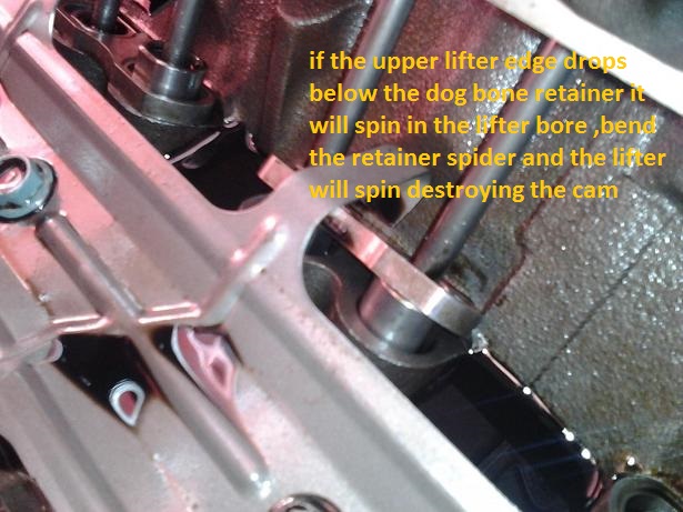
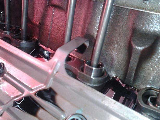
STOCK dog bone design hydraulic enclosed wheel roller lifters are generally designed for less than .550 lift and less than 6000rpm
the stock Chevy hydraulic roller lifters , dog bone and spider springs don,t always work reliably, ALL THE TIME with engines having over .500 lift or when spun over 6000rpm, its not all that rare for the lifter ,retainer to bend the retainer spring allowing the lifter to spin sideways, in the lifter bore, resulting in a destroyed cam, thats why Ive suggested BRAND NAME ,AFTERMARKET RETRO FIT CAM COMPONENTS BE USED
Question?
why use stock lifters when there are lots of much better quality hydraulic retro-fit lifters with significantly better potential rpm capability for not much more money? even if you were going to pay $200-$300 more for the linked hydraulic roller lifters, they have a significant advantage in that they don,t tend to have issues with the lifter retention spider or dog bones failing
the aftermarket linked lifters tend to handle valve lifts exceeding about .500 and rpm levels exceeding about 5800 rpm much better and with fewer issues
while I generally use stainless 6 or 8 mesh screens theres lots of options that will work just fine, just remember to keep the oil changed regularly or theres some potential for sludge to clog ANY size shrapnel screens
http://www.twpinc.com/twpinc/products/T ... 6T0350W36T
http://www.twpinc.com/twpinc/products/T ... 8S0280W36T
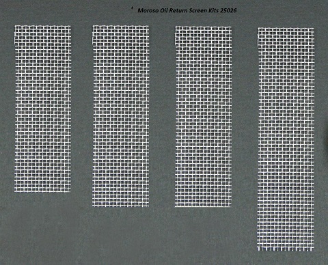
http://www.summitracing.com/parts/mor-25026?seid=srese1&gclid=COOf2IODscgCFZKAaQodHWoF1Q
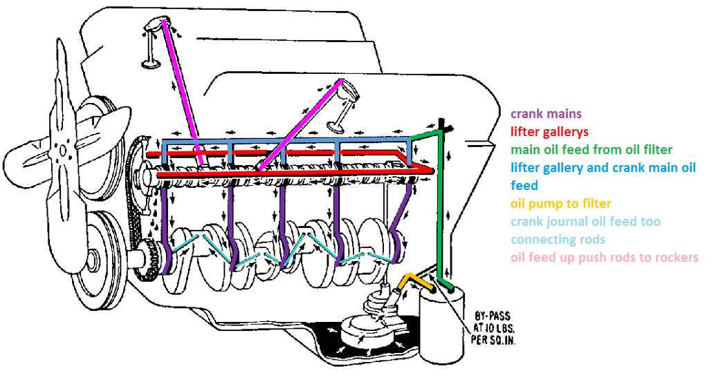
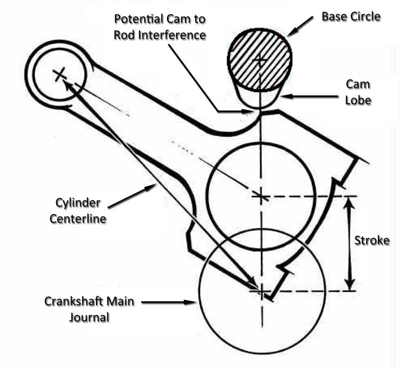
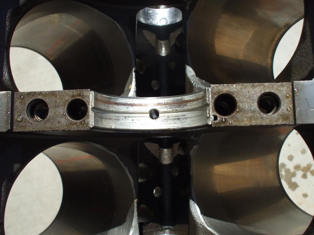
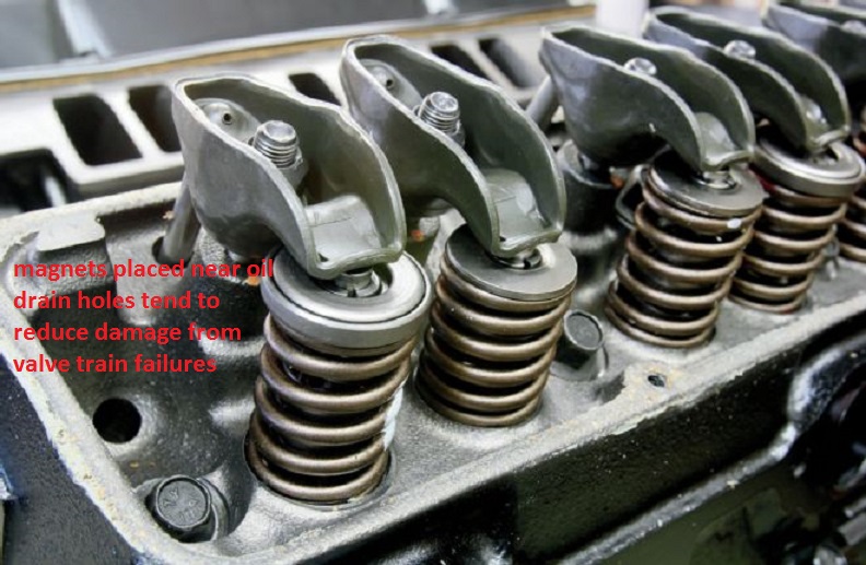
it should not take a great deal of imagination to see that a broken rocker, lifter or push-rod could dump metalic debris into an oil drain back port that wold rapidly result in increased internal engine damage as a result.
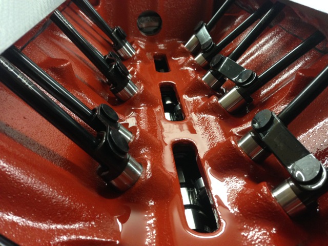
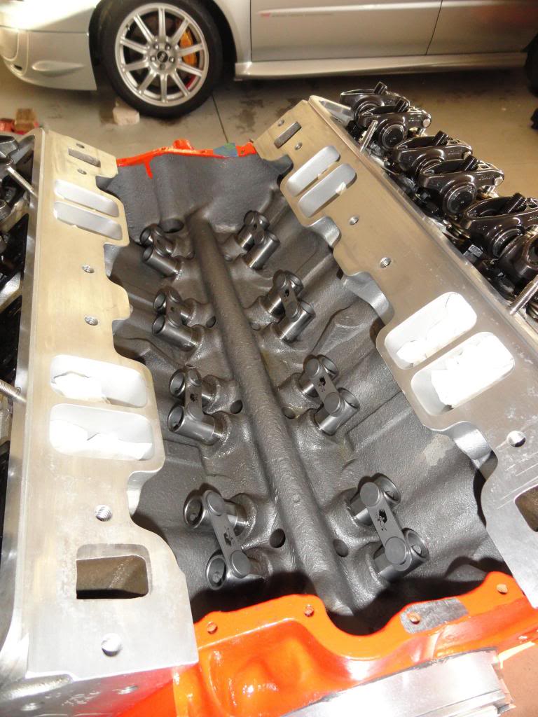
Something like this, placing magnets and shrapnel screens helps engine durability red ones in drain valley, green ones being overkill/optional?
yeah thats logical magnet locations,
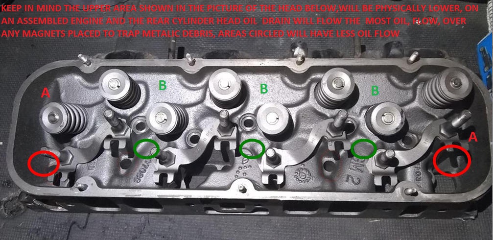
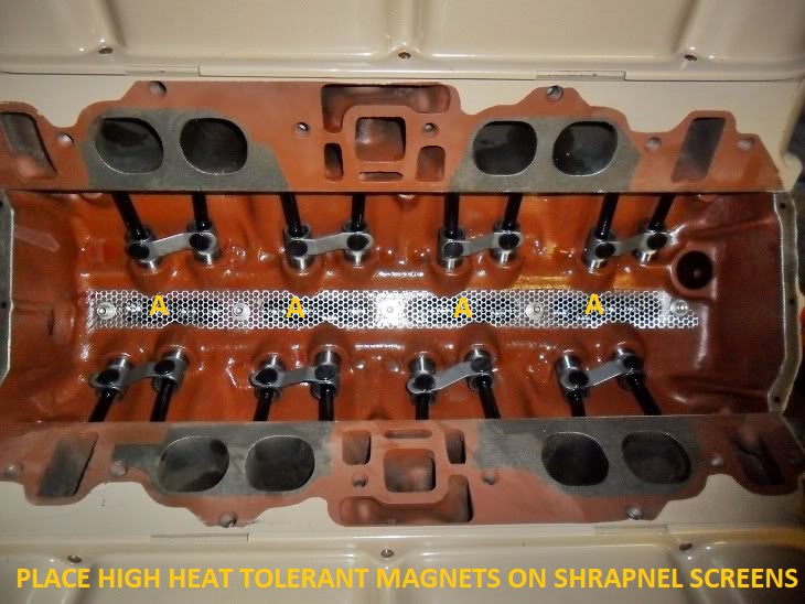
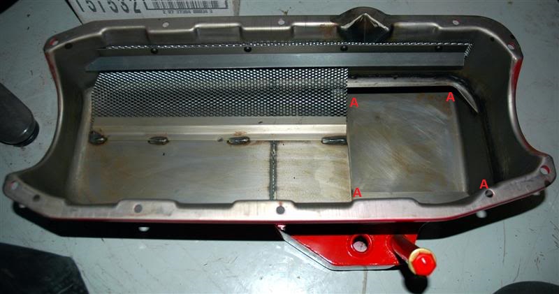

IVE typically used these magnets in an engine, one in the rear oil drain on each cylinder head, one near each lifter gallery drain and 4 in the oil pan sump
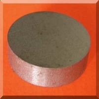
proper magnets trap metallic debris
SmCo Samarium Cobalt Disc Magnets
http://www.magnet4less.com/
http://www.summitracing.com/parts/mor-25026?seid=srese1&gclid=COOf2IODscgCFZKAaQodHWoF1Q
it should not take a great deal of imagination to see that a broken rocker, lifter or push-rod could dump metalic debris into an oil drain back port that wold rapidly result in increased internal engine damage as a result.
Something like this, placing magnets and shrapnel screens helps engine durability red ones in drain valley, green ones being overkill/optional?
yeah thats logical magnet locations,
IVE typically used these magnets in an engine, one in the rear oil drain on each cylinder head, one near each lifter gallery drain and 4 in the oil pan sump
proper magnets trap metallic debris
SmCo Samarium Cobalt Disc Magnets
http://www.magnet4less.com/
http://garage.grumpysperformance.co...-the-extra-cost-vs-a-flat-tappet-design.3802/
http://garage.grumpysperformance.co...er-lifter-install-direction.11398/#post-52208
http://garage.grumpysperformance.co...-rockers-and-the-pushrods-rub.198/#post-46839
http://garage.grumpysperformance.co...ng-pressures-don-t-work-well.1489/#post-36984
http://garage.grumpysperformance.com/index.php?threads/brand-x-vs-brand-y.8077/#post-27919
http://garage.grumpysperformance.co...ting-up-the-valve-train.181/page-2#post-19781
http://garage.grumpysperformance.co...ulic-roller-lifter-cam-dyno-comparison.12449/
http://garage.grumpysperformance.co...train-clearances-and-problems.528/#post-57678
http://www.ebay.com/itm/Lunati-7233...ro-Fit-Hydraulic-Roller-Lifters-/142214244725
http://www.ebay.com/itm/Howards-Cam...c-Roller-Lifters-V8-350-400-383-/330913878812
http://www.ebay.com/itm/HOWARDS-SBC-Chevy-Retro-Fit-Roller-278-284-500-510-114-Cam-Camshaft-Lifters/111898314084?_trksid=p2047675.c100005.m1851&_trkparms=aid=222007&algo=SIM.MBE&ao=2&asc=44730&meid=fc5419dec13f4dbd94f133f935466820&pid=100005&rk=2&rkt=6&mehot=lo&sd=111898309401
don,t forget a few magnets in the oil pan goes a long way towards trapping unwanted metallic dust formed from the cam and rings lapping in durring break-in that might otherwise get embedded in your bearings or cause other problems
here is the magnets I use in every engine
add a few magnets to the oil pan and drain back area in your engine, the trap and hold metallic dust that comes from wear and increase engine life span by preventing that crap embedding in the bearings
http://www.kjmagnetics.com/proddetail.asp?prod=D66SH
http://www.kjmagnetics.com/proddetail.asp?prod=D66SH
http://www.kjmagnetics.com/proddetail.asp?prod=D82SH
these are even more tolerant of temp swings and retain strength at even higher engine oil temps plus they are smaller and easier to use
http://www.cranecams.com/?show=reasonsForFailure
https://www.holley.com/data/Products/Te ... NST150.pdf
http://www.circletrack.com/techarticles ... index.html
http://www.cranecams.com/?show=camQuestions
stuff like this is easily avoided or fixed if you have the correct tools and experiance, BBC engines tend to require extra care during the break-in due to high lifts and strong valve springs, I tend to smear MOLY cam lube over all the valve train surfaces, break the cams in at 2000-3000 rpm and use crane break in lube also, and run a decent high zinc content oil during the first few hours
yeah, check it out, the longer you run it if the lobes are wearing the more crud your pumping thru the engine,if you did lose a lobe its USUALLY a clearance issue like spring bind, rocker to rocker stud, or retainer to valve guide , improper lash/pre load or installation issue like the wrong spring loads or improper lubrication.
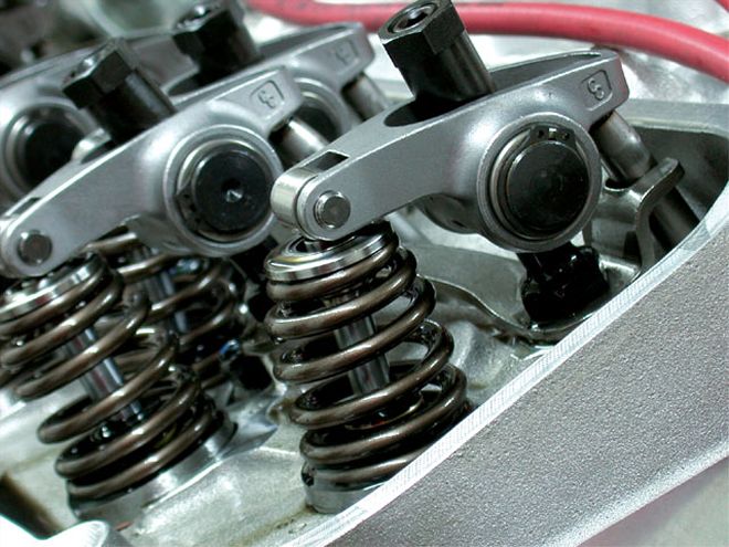
stock springs and rocker to valve stem clearance on some BBC heads won,t clear more than about .530 lift, many clear .560, but above that you almost always need to check carefully, or use aftermarket valve train components and custom machine work
the old familiar stuffs Part #1052367 is getting hard to find
E.O.S. was discontinued but.....
http://www.sdparts.com/product/1052367/GMEngineOilSupplimentEOS16ozBottle.aspx
the new stuff...
http://www.acdelco.com/html/pi_vehcare_lub.htm
(use the drop down menu)
Part 10-106
12371532
E.O.S. Assembly Lubricant (1 pint)
its still available if you know where to look, most but not all parts counter guys will know this but youll run into a few who just insist its not available
http://www.cranecams.com/?show=promo&id=48
btw MOLY base lubes are your first and best break-in lube during the first few minutes
http://www.cranecams.com/index.php?show=browseParts&lvl=2&prt=15
http://www.cranecams.com/pdf/548e.pdf
http://www.carcraft.com/techarticles/11 ... index.html
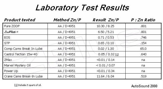
CRANES Super Lube Break-In Concentrate is an anti-wear additive formulated with a high concentration of special zinc dithiophosphate to provide sustained protection against cam lobe and lifter scuffing and wear. This oil supplement is to be added to the engine oil for the initial break-in period after the installation of a new camshaft and lifters.
Part No. 99003-1 -- 8-ounce container
http://www.digitalcorvettes.com/forums/showthread.php?t=84348
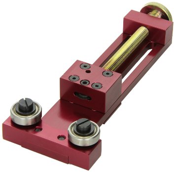
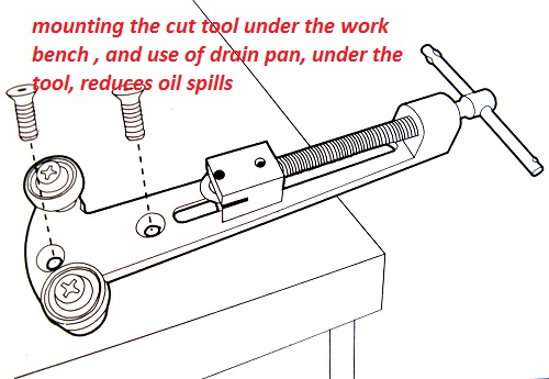
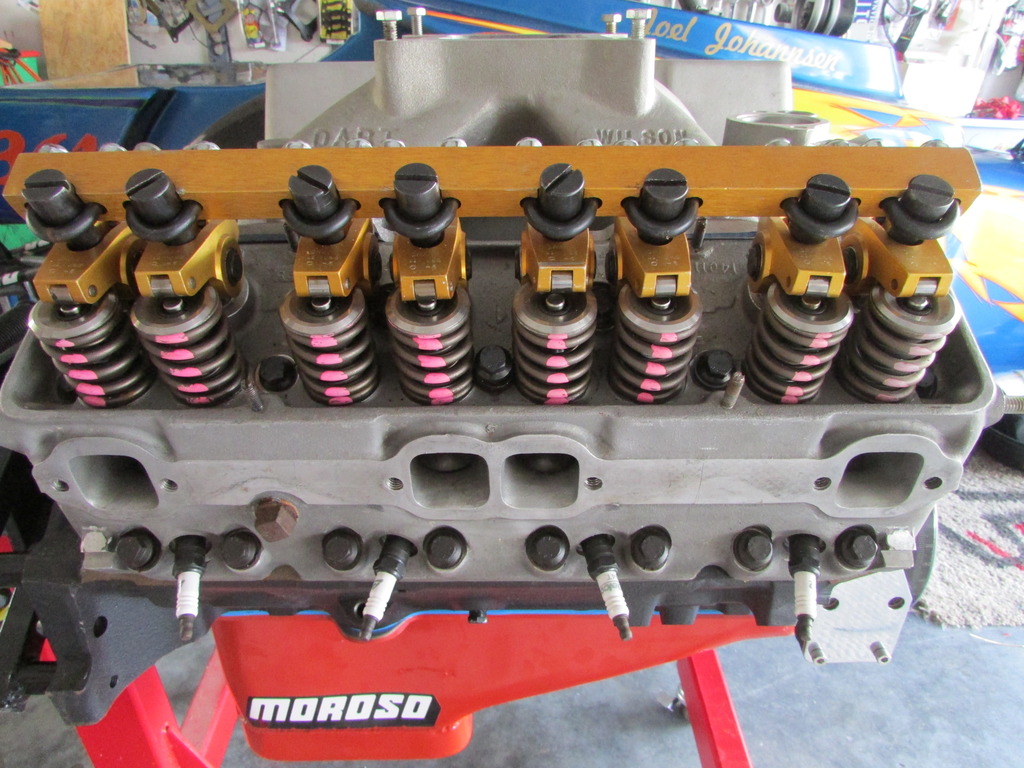
BTW before the next time you do a running valve adjustment you should find and use a set of cheap used tall valve covers which youve modified by cutting a wide slot along the center top surface, this retains a good deal more oil in the engine vs on the headers,but before assuming anything verify the old cam is having problems and your clearances/geometry on the valve train are correct
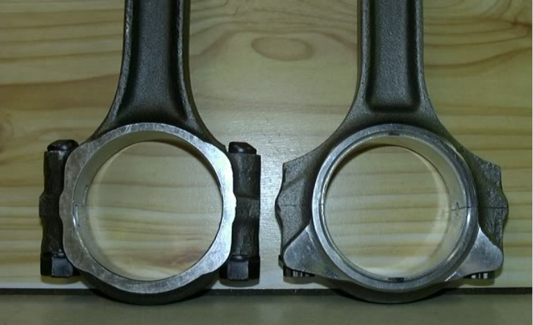
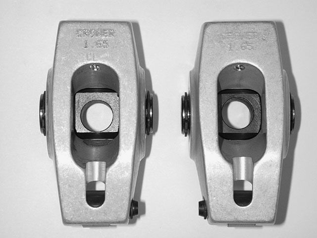
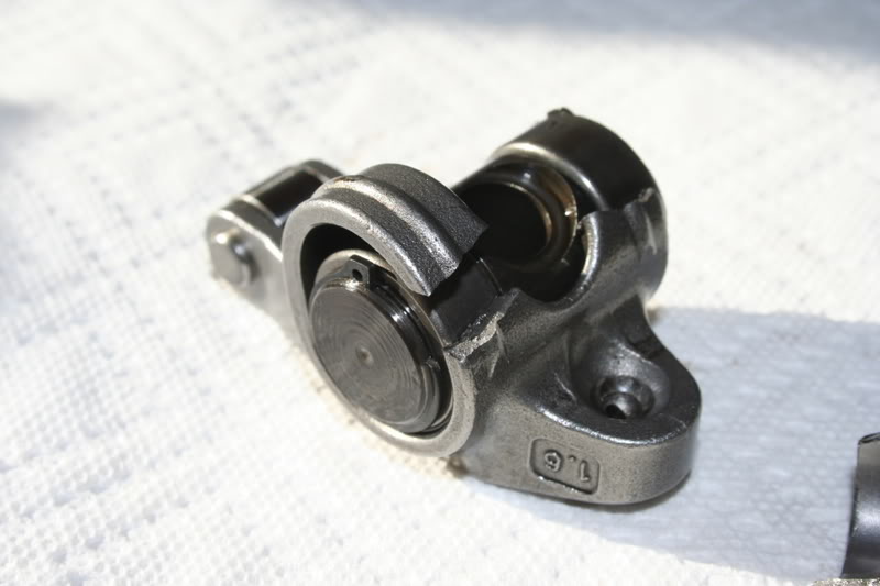
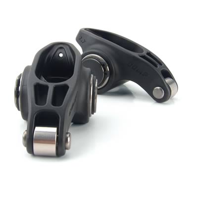
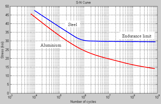
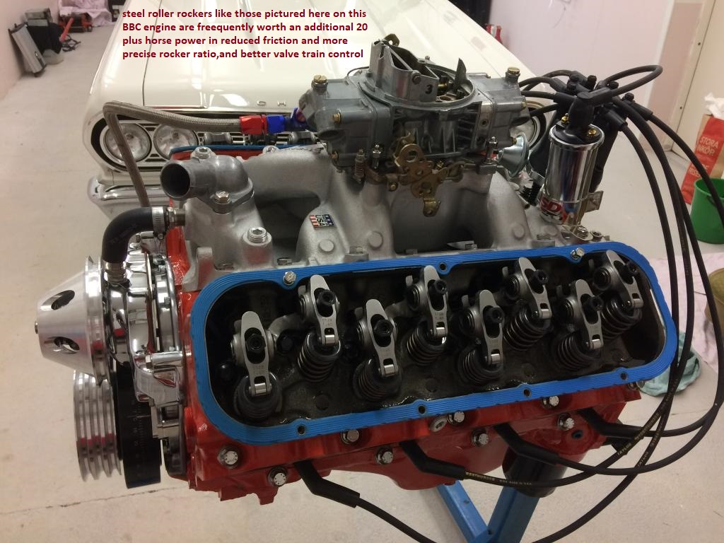
IVE always preferred STEEL roller rockers over ALUMINUM for two reasons
first STEEL has a MUCH GREATER fatigue life under repeat stress than aluminum, and steel generally has far fewer clearance insures with other components, plus some STEEL roller rockers are REBUILD ABLE
http://store.summitracing.com/partdetail.asp?part=CCA-1302-16&autoview=sku
http://store.summitracing.com/partdetail.asp?part=CRN-11600-1&autoview=sku
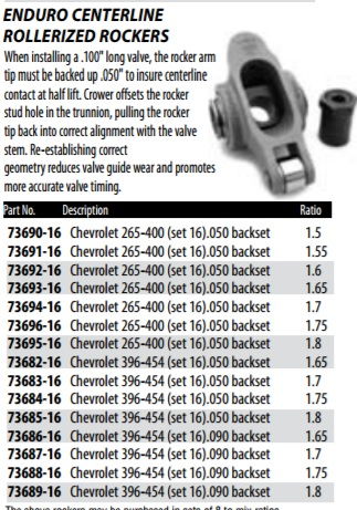
in MOST cases you can install 1.6:1 roller rockers with MINOR machine work, (I have seen on rare occasions no machine work necessary)
but in any case its easily done,
the tool comes with instructions
http://store.summitracing.com/partdetail.asp?autofilter=1&part=PRO-66485&N=700+115&autoview=sku
and before a dozen guys start telling you they installed them with zero problems on stock heads, keep in mind most guys don,t take the time to check ALL the clearances thru THE FULL rotation of the rockers arc. and it they don,t break or bind parts ,THEY assume its fine
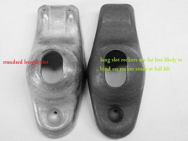
but the truth is the push rod should NEVER touch either end of the slot even lightly anywhere in the arc.
WATCH THE VIDEOS, READ THE LINKS
http://www.youtube.com/watch?v=Cqx8Cs6O ... re=related
http://www.youtube.com/watch?v=5GBNLlsi ... re=related
http://www.digitalcorvettes.com/forums/showthread.php?t=82474
https://www.centuryperformance.com/valve-adjustment-procedure.html
http://www.2quicknovas.com/happycams.html
http://www.iskycams.com/camshaft.php
http://www.reedcams.com/degreeing.htm
http://garage.grumpysperformance.com/index.php?threads/multi-angle-valve-job-related.3143/#post-8387
http://garage.grumpysperformance.co...video-with-info-worth-watching-through.15999/
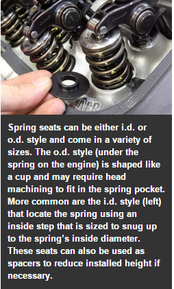
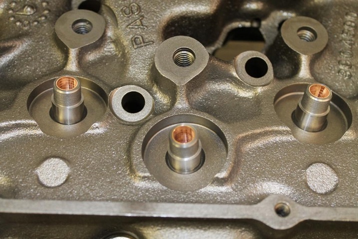
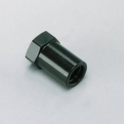
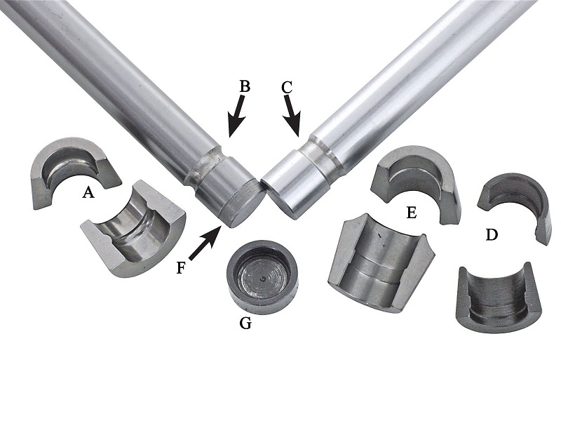
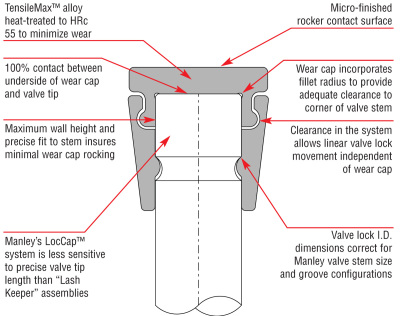
keep in mind shims under the valve springs can be used to raise the spring or shorten the valves installed height, valve locks and retainers can be purchased with non-O.E.M dimensions to adjust the valves installed height or spring load rates
you use either or both depending on the application
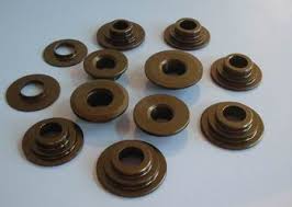
a .050 PLUS valve lock moves the retainer .050 higher on the valve stem with no other changes, a plus .050 retainer would move the retainer .050 higher with stock valve locks or an additional .050 if matched to .050 plus locks
if you used a plus .o50 retainer with a set of minus .o50 valve locks the retainer would remain at the stock height on the valve stem
Ive used CROWER,ERSON,CRANE and HERBERT valve springs but the source I use the most is these guys, (below) so Id at least suggest you look over the options, and choose what suits the budget and needs of the engine, and yeah! everything thats decent quality costs a great deal more money that you expect it too as Im all too sure that you know all too well.
http://www.racingsprings.com/
(866) 799-9417
http://www.racingsprings.com/Staff
heres their ph#
Toll Free (866) 799-9417
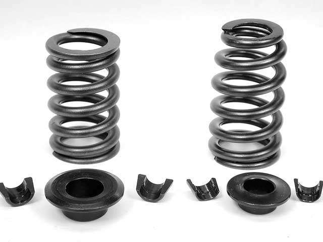
I always just order the springs. retainers. valve locks. and spring seat cups & shims as a package deal (NOT CHEAP BUT EVERYTHING WORKS AND FITS) then you just need shims under the valve spring seats occasionally to get the correct installed height
THREADS THAT MIGHT HELP
http://garage.grumpysperformance.co...e-springs-and-setting-up-the-valve-train.181/
http://garage.grumpysperformance.com/index.php?threads/valve-train-clearances-and-problems.528/
http://garage.grumpysperformance.co...-loads-and-installed-height.10709/#post-46658
http://garage.grumpysperformance.com/index.php?threads/busted-valve-spring.7716/#post-29797
HERES OTHER TOOLS YOU MIGHT NEED

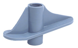
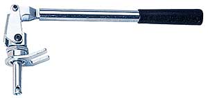
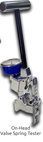
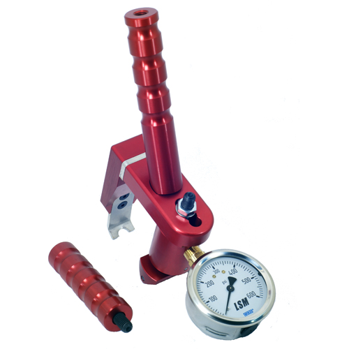
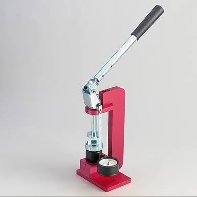
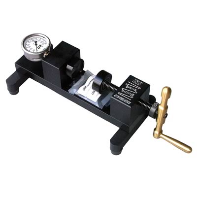
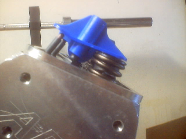
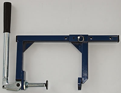
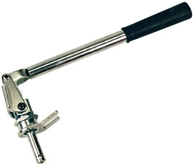
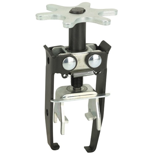
valve spring compressors
yes I'm aware a few guys would prefer being skinned alive and dipped in alcohol to reading links!
but for those guys who care to learn more these links might be useful
http://garage.grumpysperformance.co...e-springs-and-setting-up-the-valve-train.181/
http://garage.grumpysperformance.com/index.php?threads/valve-train-clearances-and-problems.528/
http://garage.grumpysperformance.com/index.php?threads/valve-springs.9613/#post-50534
http://garage.grumpysperformance.co...-loads-and-installed-height.10709/#post-46662
http://garage.grumpysperformance.co...u-buy-bare-or-assembled-heads.534/#post-41292
http://garage.grumpysperformance.com/index.php?threads/busted-valve-spring.7716/#post-38047
http://garage.grumpysperformance.co...pring-cooling-via-engine-oil.6491/#post-20681
http://garage.grumpysperformance.com/index.php?threads/vortec-spring-upgrade.6175/#post-19304
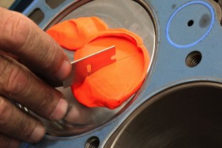
http://garage.grumpysperformance.com/index.php?threads/checking-piston-to-valve-clearances.399/
http://garage.grumpysperformance.co...per-valve-spring-seats-shims.1005/#post-15534
http://www.summitracing.com/parts/pro-66830/overview/
https://www.harborfreight.com/multipositional-magnetic-base-with-fine-adjustment-5645.html
https://www.harborfreight.com/catalogsearch/result/index/?dir=asc&order=EAScore,f,EAFeatured+Weight,f,Sale+Rank,f&q=indicator+stand
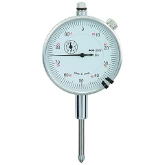
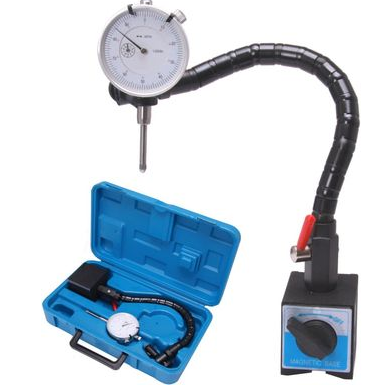
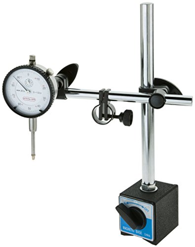
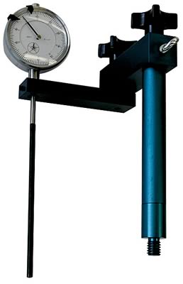
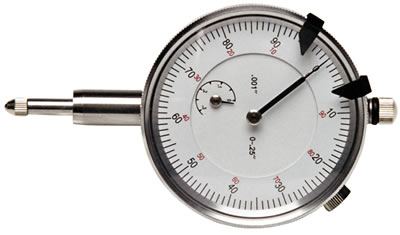
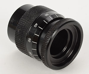
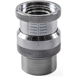
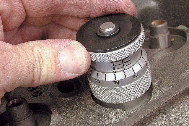
almost every mechanics tool box needs a few basic measuring tools and supplies
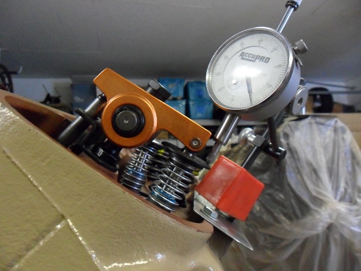
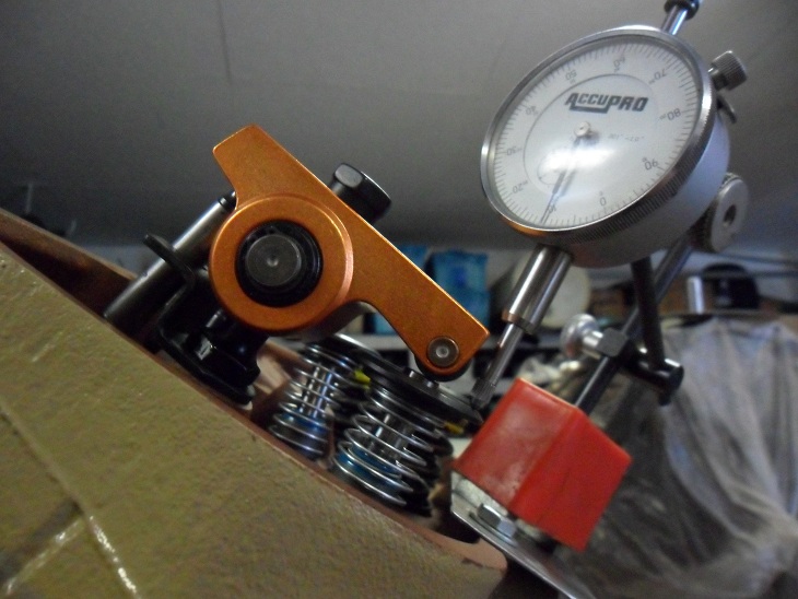
If you suspect a worn cam lobe, checking the cams lobe lift with a dial indicator on the valve spring retainer vs the other lobes would certainly provide useful related info.
knowing vs guessing helps in making decisions wisely
http://www.summitracing.com/parts/pro-66830/overview/
https://www.harborfreight.com/multipositional-magnetic-base-with-fine-adjustment-5645.html
https://www.harborfreight.com/catalogsearch/result/index/?dir=asc&order=EAScore,f,EAFeatured+Weight,f,Sale+Rank,f&q=indicator+stand
http://www.utrechtart.com/Plastalin...currency=USD&gclid=CN3G75zOw80CFQgaaQodKbgFjA
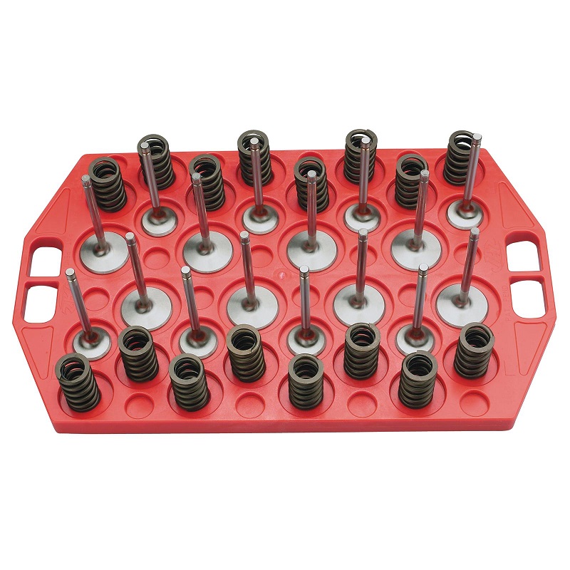
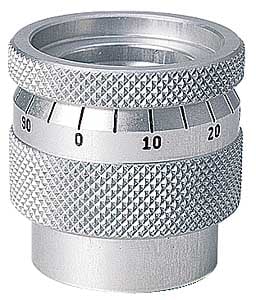
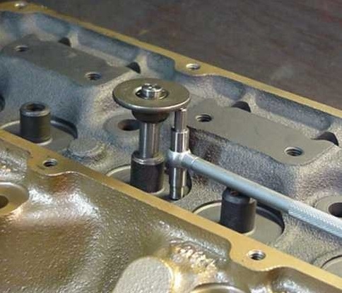
When checking valve spring installed height and valve clearances you can,t guess,.its mandatory you don,t guess and actually measure clearances, valve spring micrometers are not expensive and owning or borrowing one for your engine assembly makes a good deal of sense, you can get close with SNAP GAUGES, and a 2" standard micrometer or a vernier caliper, while valve springs won't increase lift, (thats dependent on cam lobe and the rocker ratio) the proper combo of shims, retainers, valve springs, and keepers and in some cases longer valves can effectively increase valve train clearance
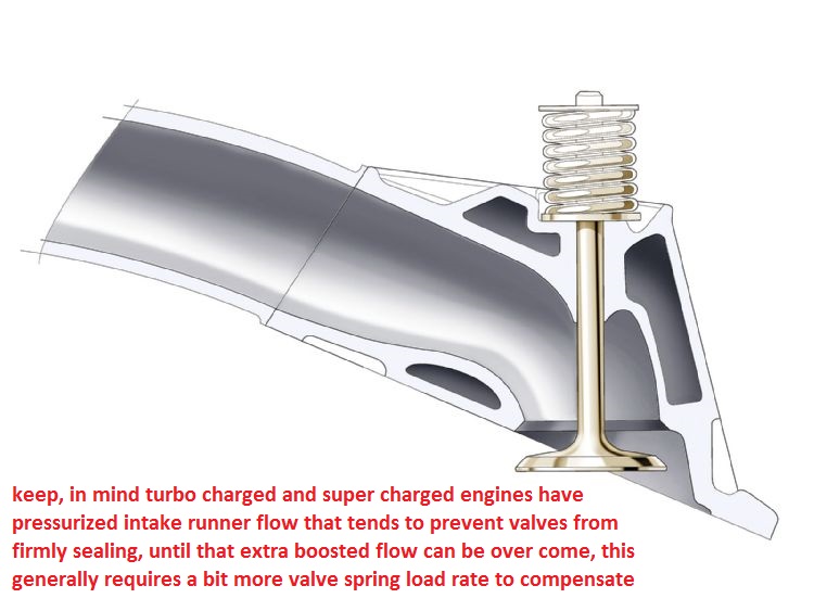
all turbo and super charged engines, bring into play an additional factor when you set up your engines valve train, and select valve springs.
you might want to change too or select better and upgraded valve springs simply because a boosted or supercharged engine obviously has pressure in the intake runners and what most guys fail to understand is that that means theres about 3.2 square inches of intake valve and if theres 10 lbs of boost the result is it requires about 30 lbs more effective spring seat pressure to firmly seat the valve on its seat at higher rpms,add the fact that valve springs lose tension over time bue to heat and constant stress and your 100% sure to see a loss of consistent valve train component control, at a lower rpm than the identical cam used without boost, with identical spring installed height and seat and full lift load numbers.
if youve ever stuck your thumb over a garden hose trying to stop the water flow youll realise that sealing it against flow requires a good deal of force
If your ordering any cam, be very sure you explain what year block and what cylinder heads will be used as there are differences in the cams. between early and later SBC, block s and the cams they require,and on big blocks theres similar issues, a mark VI cam is different from a MARK IV cam
http://www.grumpysperformance.com/flowridge1.png[\img]
any time you change cams youll need to use a matching distributor gear, the cam manufacturer should be able to help tell you what matches, obviously checking clearances helps
and dipping the gear in moly assembly lube before it installed helps
be sure you inspect the distributor gear for excessive wear
especially if you changed from a flat tappet to a roller cam.
if your seeing the timing change a few degrees, back and forth,
slack in a worn, loose timing chain, worn distributor gear or not having the proper shim clearance on the distributor center shaft will provide slop that allows timing to vary several degrees
http://www.kmotion.biz/instht.htm
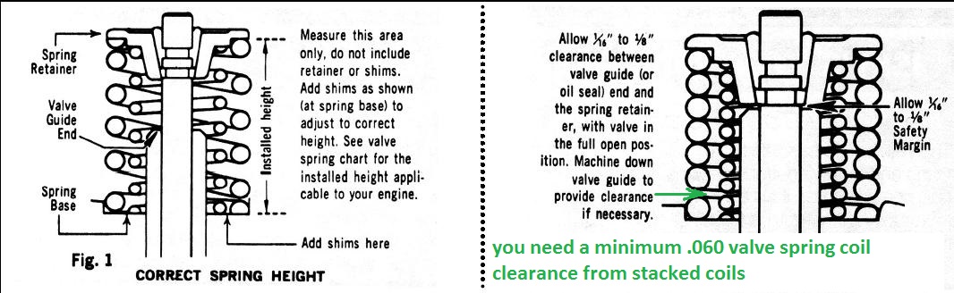
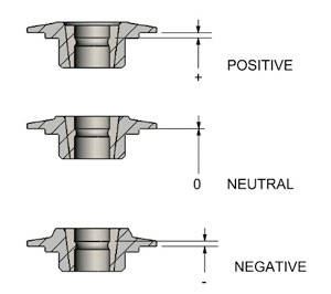
there are PLUS .050, standard and NEG .050 height retainers and valve cups and shims to adjust the installed valve spring height and location in regard to the cylinder head and valve guides
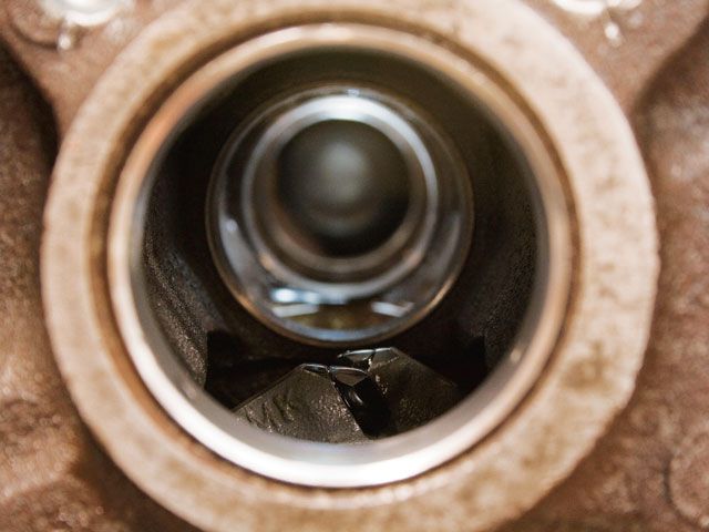
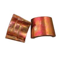
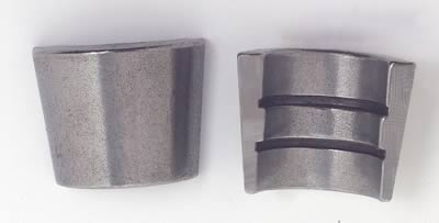
If the valve springs are to be removed with the heads still on the car,
the last thing you want is too remove a valve spring and have the valve to drop into the cylinder,
if you use air the crank tends to want to spin the crank to BDC, youll want to verify TDC ,
and make sure the flywheels temporarily prevented from turning from that the TDC position,
Ive used both methods both work,you can put 6 ft of rope in the cylinder while its in BDC then turn it to TDC, Ive used both with zero issues,
If you use the compressor youll want to keep it at 120 psi and constantly feeding pressurized air to keep the valves held in place,
and theres a small chance the compressor pushes enough moisture to allow water to accumulate in the cylinders,
so be sure you spin the engine with the starter with the spark plugs removed several times before you re-install plugs.
if you use the rope, theres a very low chance that the rope will tangle and form a knot that makes removal difficult
http://www.lunatipower.com/Tech/Valvetrain/HowToVerifyValvetrainGeometry.aspx
http://garage.grumpysperformance.co...alves-and-polishing-combustion-chambers.2630/
http://garage.grumpysperformance.co...ck-chevy-gen-v-vi-to-adjustable-rockers.4564/
http://www.summitracing.com/search/...d-length-checkers?autoview=SKU&ibanner=SREPD5
Proform Pushrod Length Checkers 66789 SBC 3/8" rocker studs
Proform Pushrod Length Checkers 66790 SBC 7/16" rocker studs
Proform Pushrod Length Checkers 66806 BBC 7/16" rocker studs
Parts List for Ask Away: Big Block Chevy 454 Pushrod Length
| Part Number | Description |
|---|---|
| CCA-7702-1 | COMP Cams Hi-Tech Pushrod Length Checking Tool, 6.80" - 7.80" (Intake) |
| CCA-7703-1 | COMP Cams Hi-Tech Pushrod Length Checking Tool, 7.80" - 8.80" (Intake) |
| CCA-7704-1 | COMP Cams Hi-Tech Pushrod Length Checking Tool, 8.80" - 9.80" (Exhaust) |
| CCA-7900 | COMP Cams Magnum Checking Pushrod Set* |
| *Master Kit: five separate adjustable pushrods from 6.125" to 11.50". |
heres a bit of useful related push rod length info
Big Block Chevy, Standard Length Big Block Intake 3/8" / .080" 8.275"
295-7941-8 Big Block Chevy, Standard Length Big Block Exhaust 3/8" / .080" 9.250"
295-7969-8 Big Block Chevy, Standard Big Block +.100" Long Intake 3/8" / .080" 8.375"
295-7979-8 Big Block Chevy, Standard Big Block +.100" Long Exhaust 3/8" / .080" 9.350"
295-7951-8 Big Block Chevy, Standard Length Big Block Tall Deck Intake 3/8" / .080" 8.675"
295-7961-8 Big Block Chevy, Standard Length Big Block Tall Deck Exhaust 3/8" / .080" 9.650"
295-7800 V8 396-454 Retro Fit Pushrod Set, Intake & Exhaust, 1965-Present
3/8" / .080"
3/8" / .080" 7.725 Int.
8.675 Exh
295-7913-16 Small Block Chevy, Standard Length Small Block Chevy 3/8" / .080" 7.800"
295-7984-16 Small Block Chevy, +.100" Long 3/8" / .080" 7.900"
295-7934-16 Big Block Ford, Standard Length Ford `72-'78 429-460 3/8" / .080" 8.550"
295-7951-16 Big Block Ford, Standard Length Ford `69-'71 429-460 3/8" / .080" 8.675"
295-7582-16 Oldsmobile, Std Length 455 5/16" 9.550"
http://www.racingsprings.com/
preventing cam & lifter break-in failures
watch this video, it depicts the lifters movement as the cam lobe rotates under its base forcing it up as the lobes ramp, rotates under the lifter base,removing the clearance slack,
as it compresses the valve spring and forces the trapped oil, up the push rod and lifts the valve
so you can order the correct length push rods...
I don,t think you have the correct idea as to how hydraulic lifters work,
yes it is possible for an engine with hydraulic lifters to be pushed too operate at a high enough rpm that the time required for the lifter seat to fully depress and all the oil too be forced up to the push rod/rockers , to be so short that the lifter pumps up and the valves will have less seat time, ( sometimes one of several factors, like the lifter leaving the cam lobes surface as the inertial loads exceed the valve springs ability to maintain lifter too lobe contact, referred too or contributing to what is commonly referred too as valve float) but that has ZERO to do with selecting push rod length or proper valve train geometry, (remember at 6000 rpm the valve is lifted off its seat 50 times PER SECOND)
it only takes a few seconds running a new engine for an improperly installed cam , lifters and valve train, during the break-in process to generate teaspoons of metallic trash that ,once in the engine oil flow ,rapidly destroys bearings if the clearances ,spring load rates or valve train geometry is wrong
it should be rather obvious that there's options,you'll chose in both valve train components and lubricants, cam failures are usually the result of incorrect CLEARANCES or too much SPRING PRESSURE or LACK of ADEQUATE LUBRICATION,USE DECENT MOLY CAM LUBE, and decent quality oil, adding MAGNETS to trap metallic CRUD HELPS, if your not getting constant oil flow from each rocker /push rod at idle theres something wrong and that needs to be checked
yeah! as I stated it varies with engine cam used and application,yes BBC valve springs tend to be larger as the valves weigh more, but generally theres not a huge amount of compression during the install and obviously the cam generally comes with the installed height, valve spring part numbers and intended load rates that should be used, and yes you still need to use shims, valve spring cups and watch out that at max lift you still maintain the required clearances
changing valve springs on the car
now most shops will rotate the cylinder to TDC and install an adapter for an air hose and pump a steady 100-130psi into the cylinder to hold the valves closed, but theres frequently clearance problems with headers and the adapters or hose and since you need to wack the valve retainer with a...
garage.grumpysperformance.com
BEEHIVE SPRINGS GIVE A GOOD DEAL MORE ROCKER TO RETAINER CLEARANCE
if you change the rocker ratio the push rod alignment changes and you might need a LUIS TOOL to lengthen the cylinder head clearance slots in the cylinder heads.
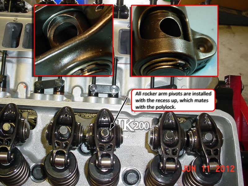
be sure to check clearances carefully like coil bind,and push-rod to guide plate alignment and clearances ,verify the rocker slots don,t bind on the rocker studs as this is a common problem with stock stamped style 1.6:1 ratio rocker, verify the push rods don,t bind in the slots in the cylinder head, if they do even for an instant at one point in the rockers arc, they can bind the lifter rotation on the cam lobe and cause the cam to wipe, out the lobe and the lobe & lifter contact area resulting in a quickly failed cam,and/or restrict oil to the rockerss
check all valve train geometry and clearance on any engine you assemble or modify the valve train on.
READ
http://rehermorrison.com/tech-talk-86-spin-and-win-evaluating-valvetrains-the-old-fashioned-way/
http://www.hotrod.com/techarticles/engi ... index.html
these adjustable push rod guide plates come in handy at times
(1) get a decent ROLLER CAM, add a high volume oil pump, baffled 8 qt oil pan, with a windage screen and check your clearances and avoid the problem,USE DECENT MOLY CAM LUBE,and decent quality oil,adding MAGNETS to trap metallic CRUD HELPS
(2) use a SOLID lifter flat tappet cam with lifters with the lube feed holes,add a high volume oil pump, baffled 8 qt oil pan, with a windage screen and check your clearances and avoid the problem,USE DECENT MOLY CAM LUBE, and decent quality oil,adding MAGNETS to trap metallic CRUD HELPS
http://www.competitionproducts.com/prodinfo.asp?number=651080DL
(3) mod the lifter bores for more oil flow,add a high volume oil pump, baffled 8 qt oil pan, with a windage screen and check your clearances and avoid the problem,USE DECENT MOLY CAM LUBE,and decent quality oil,adding MAGNETS to trap metallic CRUD HELPS
http://www.compperformancegroupstores.c ... gory_Code=
(4)USE DECENT MOLY CAM LUBE
http://www.cranecams.com/index.php?show ... l=2&prt=15 ,
add a high voluum oil pump, baffled 8 qt oil pan, with a windage screen and check your clearances and avoid the problem,and decent quality oil,adding MAGNETS to trap metalic CRUD HELPS
(5) thinking things thru and verifying clearances and spring pressures, and having a well thought thru lube system will significantly lower your chances of having problems,USE DECENT MOLY CAM LUBE,and decent quality oil,adding MAGNETS to trap metallic CRUD HELPS
.......I have not seen a cam fail in years UNLESS the guy installing it failed to follow those tips
https://www.ebay.com/i/402584062207...1291&msclkid=d17e7155654a1a20769a115a09f43c68
if the lifter base is well worn you can bet the farm the cam lobe is most likely also worn, and you'll need a lifter removal tool to pull the damage lifters up out through the blocks lifter bores
If you have questions, you can reach their tech department at 800-641-7920.
most cam manufacturers do extensive testing with each engine design to verify the limits and limitations of each engines valve train design, so it generally helps to talk with the cam suppliers tech department engineers.
cam lobe acceleration / de-acceleration rates have a large effect on the required spring load rates, as do rocker ratios and cam lobe size and lifter diameters.
sellecting valve springs, and setting up the valve train
How do you determine the spring pressure needed to keep the valves under control for a given lift, duration, and max rpm. It might take you several hours to read thru all the links and sub links but its time very well spent as it could save your engine from destruction and save you thousands of...
garage.grumpysperformance.com
Solid Flat Tappet Camshaft: 130 lbs Seat Pressure/300-325 lbs open pressure
Hydraulic Roller Camshaft: 130-140 lbs Seat Pressure/300- 355 lbs open pressure
Solid Roller Camshaft: (Minimum Safe Pressures DEPEND ON SEVERAL FACTORS)
Up to .600Ë valve lift: 200-235 lbs Seat Pressure/600 lbs open pressure
Over .600Ë valve lift: 250-280 lbs Seat pressure /100 lbs pressure for every .100Ë of valve lift
many more modern oil formulations lack the correct additives for flat tappet lifters, so be very sure you check to see what oil your using and if its designed for flat tappet lifter applications
Id also point out that youll want to lubricate any valve you install in a valve guide and verify the valve train clearances very carefully, and use the correct valve springs and add the correct valve seals installed
anyone see a PATTERN?
http://garage.grumpysperformance.com/index.php?threads/removing-valve-seals.4283/
you might want to read thru this AGAIN
http://www.highperformancepontiac.com/t ... index.html
http://www.cranecams.com/?show=article&id=2]http://www.cranecams.com/?show=article&id=2
FROM MORTEC
If you are building a SMALL or BIG block Chevy with a flat tappet cam, (solid or hydraulic lifters) be careful during the initial engine break in. It is very easy to lose a cam lobe and lifter during initial break in. This is especially true with a higher than stock lift cam and higher pressure valve springs. The increased push rod angles found on the BBC and poor preparation can make cam lobe failure after initial fire up a distinct possibility. You can help prevent this cam lobe failure by making sure the engine is pre-lubed prior to initial fire up. Use a good high pressure lube on the cam lobes and lifter bottoms during assembly. If possible use a lighter pressure stock valve spring (or if using a valve spring with multiple springs, take out some of the inner springs) to initially run the engine. Then switch to the heavier pressure springs after break in. When the engine is first fired up, keep the engine rpms at 2,500 or above, don't let the engine idle for 20 minutes or longer. This keeps lots of oil splashing up on the cam lobes. Make sure the engine can be run for this time period by having enough fuel available, ignition timing set correctly, coolant available for the motor, valve lash set correctly, etc. The idea is not to crank the motor over excessively before it starts up for the first time. If your BBC flat tappet cam survives this initial break in period, it will be good to go for many miles. After the initial engine break in, drain the oil and change the oil filter. Roller cams generally do not suffer these types of cam lobe failures during initial engine fire up.
if you've adjusted the valves correctly the lifter spins at all rpm levels,but that does NOT mean it wears EVENLY at all rpm levels due to several factors if you look closely AT FLAT TAPPET CAMS you'll see that the center of the cam lobe is NOT centered under the lifter and that the lifter surface is slightly angled , BOTH these factors force the lifter to spin in its bore as the lobe passes under the lifter slightly off center.
SOME of the reasons the higher rpm durring the break in phase is important is that
(1) the faster RPMs the better chances the lobe passes under the lifter floated on an oil film and the less time the oil film has to squeeze out between them
(2) the higher the RPM the greater the oil volume and pressure the engine pumps and the more oil flow is available at the lobes
(3)the higher the rpm level the more oil is thrown from the rods onto the cam lobes
(4)the higher the rpm the greater the lifters weight and inertia tends to compensate for the springs pressure and lower the net pressure as the lifter passes over the cam lobes nose
(5) at higher rpm speed the better chance a small wedge of oil is trapped between the lifter base and lobe from the oil thrown from the lobes surface by centrifugal force
(6) two different metal surfaces scraping past each other at low speeds may tend to wear and GALL as the oil is squeezed out but two different hardness steel surfaces that impact each other at higher speeds covered with oil tend to work harden as they mate and will tend to be separated by that oil
(7)as the lifter spins in its bore the contact point between the lobe and lifter base constantly changes and rotates with the lobe contact point not resisting its passage and the higher the rpms the faster the lifter rotates and the less time the lobe spends at any one point
BTW ADD E.O.S. to the oil and MOLY break-in lube to the cam
before starting the engine and pre-fill the filter and pre-prime the oil system before starting the engine.
I normally pour it in just before starting the engines cam break in,procedure. because I want to make sure that nothing in the oil/E.O.S. mix can settle out from sitting over a long period of time. now if your running a flat tappet cam you should have also used a moly cam lube on the lobes and be useing a mineral base oil for the break-in procedure, and youll need to do an oil and filter change after about the first 3-4 hours running time to remove that moly cam lube from the engine after its served its purpose of protecting the cams lobes and lifters at start up, aND AS THE LOBES/LIFTERS LAPPED IN. MOSTLY to prevent that moly grease and E.O.S from potentially partially clogging the filter after that mix cools down,but also because both those lubes might leave deposits in the combustion chamber ,over time that might aggravate detonation.
even G.M. suggests that E.O.S. is not a great long term oil supplement, and that its main function is to add extra oil film strength durring new engine break in.
Isky claims that the Comp XE cams violate the 47.5% rule. The 47.5% rule applies to flat tappet cams for SBCs with 1.5 rockers but the concept is still the same for other configurations where the designs are "on the edge" or "over the edge" for lobe intensity. For 1.5 ratio SBCs, the duration at .050 must exceed 47.5% of the total valve lift or your asking valve train problems. For example, take a Comp Cams Magnum 280H, with 230 duration and, 480 lift...230/.480 = 47.9% which exceeds 47.5% therefore would not pose a threat to components. We do not regularly hear about the older, safer HE and Magnum designs rounding off lobes anywhere near as often as the XE cam designs. Unfortunately, some of the Comp Cams XE dual pattern lobes break this 47.5% rule on the intake side so they are likely to be problematic. The design has "steeper" ramps that are too quick for durability and reliability according to other cam manufacturers. They will wipe lobes in a heart beat especially if you have not followed the proper break-in procedure. Other designs are more forgiving during break-in and less likely to fail.
http://www.gmpartsdirect.com/results.cf ... number=EOS
STOCK dog bone design hydraulic enclosed wheel roller lifters are generally designed for less than .550 lift and less than 6000rpm
the stock Chevy hydraulic roller lifters , dog bone and spider springs don,t always work reliably, ALL THE TIME with engines having over .500 lift or when spun over 6000rpm, its not all that rare for the lifter ,retainer to bend the retainer spring allowing the lifter to spin sideways, in the lifter bore, resulting in a destroyed cam, thats why Ive suggested BRAND NAME ,AFTERMARKET RETRO FIT CAM COMPONENTS BE USED
Question?
why use stock lifters when there are lots of much better quality hydraulic retro-fit lifters with significantly better potential rpm capability for not much more money? even if you were going to pay $200-$300 more for the linked hydraulic roller lifters, they have a significant advantage in that they don,t tend to have issues with the lifter retention spider or dog bones failing
the aftermarket linked lifters tend to handle valve lifts exceeding about .500 and rpm levels exceeding about 5800 rpm much better and with fewer issues
while I generally use stainless 6 or 8 mesh screens theres lots of options that will work just fine, just remember to keep the oil changed regularly or theres some potential for sludge to clog ANY size shrapnel screens
http://www.twpinc.com/twpinc/products/T ... 6T0350W36T
http://www.twpinc.com/twpinc/products/T ... 8S0280W36T
while I generally use stainless 6 or 8 mesh screens theres lots of options that will work just fine, just remember to keep the oil changed regularly or theres some potential for sludge to clog ANY size shrapnel screens
http://www.twpinc.com/twpinc/products/T ... 6T0350W36T
http://www.twpinc.com/twpinc/products/T ... 8S0280W36T
http://www.summitracing.com/parts/mor-25026?seid=srese1&gclid=COOf2IODscgCFZKAaQodHWoF1Q
it should not take a great deal of imagination to see that a broken rocker, lifter or push-rod could dump metalic debris into an oil drain back port that wold rapidly result in increased internal engine damage as a result.
Something like this, placing magnets and shrapnel screens helps engine durability red ones in drain valley, green ones being overkill/optional?
yeah thats logical magnet locations,
IVE typically used these magnets in an engine, one in the rear oil drain on each cylinder head, one near each lifter gallery drain and 4 in the oil pan sump
proper magnets trap metallic debris
SmCo Samarium Cobalt Disc Magnets
http://www.magnet4less.com/
http://garage.grumpysperformance.co...-the-extra-cost-vs-a-flat-tappet-design.3802/
http://garage.grumpysperformance.co...er-lifter-install-direction.11398/#post-52208
http://garage.grumpysperformance.co...-rockers-and-the-pushrods-rub.198/#post-46839
http://garage.grumpysperformance.co...ng-pressures-don-t-work-well.1489/#post-36984
http://garage.grumpysperformance.com/index.php?threads/brand-x-vs-brand-y.8077/#post-27919
http://garage.grumpysperformance.co...ting-up-the-valve-train.181/page-2#post-19781
http://garage.grumpysperformance.co...ulic-roller-lifter-cam-dyno-comparison.12449/
http://garage.grumpysperformance.co...train-clearances-and-problems.528/#post-57678
http://www.ebay.com/itm/Lunati-7233...ro-Fit-Hydraulic-Roller-Lifters-/142214244725
http://www.ebay.com/itm/Howards-Cam...c-Roller-Lifters-V8-350-400-383-/330913878812
http://www.ebay.com/itm/HOWARDS-SBC-Chevy-Retro-Fit-Roller-278-284-500-510-114-Cam-Camshaft-Lifters/111898314084?_trksid=p2047675.c100005.m1851&_trkparms=aid=222007&algo=SIM.MBE&ao=2&asc=44730&meid=fc5419dec13f4dbd94f133f935466820&pid=100005&rk=2&rkt=6&mehot=lo&sd=111898309401
don,t forget a few magnets in the oil pan goes a long way towards trapping unwanted metallic dust formed from the cam and rings lapping in durring break-in that might otherwise get embedded in your bearings or cause other problems
here is the magnets I use in every engine
add a few magnets to the oil pan and drain back area in your engine, the trap and hold metallic dust that comes from wear and increase engine life span by preventing that crap embedding in the bearings
http://www.kjmagnetics.com/proddetail.asp?prod=D66SH
http://www.kjmagnetics.com/proddetail.asp?prod=D66SH
http://www.kjmagnetics.com/proddetail.asp?prod=D82SH
these are even more tolerant of temp swings and retain strength at even higher engine oil temps plus they are smaller and easier to use
http://www.cranecams.com/?show=reasonsForFailure
https://www.holley.com/data/Products/Te ... NST150.pdf
http://www.circletrack.com/techarticles ... index.html
http://www.cranecams.com/?show=camQuestions
stuff like this is easily avoided or fixed if you have the correct tools and experiance, BBC engines tend to require extra care during the break-in due to high lifts and strong valve springs, I tend to smear MOLY cam lube over all the valve train surfaces, break the cams in at 2000-3000 rpm and use crane break in lube also, and run a decent high zinc content oil during the first few hours
yeah, check it out, the longer you run it if the lobes are wearing the more crud your pumping thru the engine,if you did lose a lobe its USUALLY a clearance issue like spring bind, rocker to rocker stud, or retainer to valve guide , improper lash/pre load or installation issue like the wrong spring loads or improper lubrication.
stock springs and rocker to valve stem clearance on some BBC heads won,t clear more than about .530 lift, many clear .560, but above that you almost always need to check carefully, or use aftermarket valve train components and custom machine work
the old familiar stuffs Part #1052367 is getting hard to find
E.O.S. was discontinued but.....
http://www.sdparts.com/product/1052367/GMEngineOilSupplimentEOS16ozBottle.aspx
the new stuff...
http://www.acdelco.com/html/pi_vehcare_lub.htm
(use the drop down menu)
Part 10-106
12371532
E.O.S. Assembly Lubricant (1 pint)
its still available if you know where to look, most but not all parts counter guys will know this but youll run into a few who just insist its not available
http://www.cranecams.com/?show=promo&id=48
btw MOLY base lubes are your first and best break-in lube during the first few minutes
http://www.cranecams.com/index.php?show=browseParts&lvl=2&prt=15
http://www.cranecams.com/pdf/548e.pdf
http://www.carcraft.com/techarticles/11 ... index.html
CRANES Super Lube Break-In Concentrate is an anti-wear additive formulated with a high concentration of special zinc dithiophosphate to provide sustained protection against cam lobe and lifter scuffing and wear. This oil supplement is to be added to the engine oil for the initial break-in period after the installation of a new camshaft and lifters.
Part No. 99003-1 -- 8-ounce container
http://www.digitalcorvettes.com/forums/showthread.php?t=84348
BTW before the next time you do a running valve adjustment you should find and use a set of cheap used tall valve covers which youve modified by cutting a wide slot along the center top surface, this retains a good deal more oil in the engine vs on the headers,but before assuming anything verify the old cam is having problems and your clearances/geometry on the valve train are correct
IVE always preferred STEEL roller rockers over ALUMINUM for two reasons
first STEEL has a MUCH GREATER fatigue life under repeat stress than aluminum, and steel generally has far fewer clearance insures with other components, plus some STEEL roller rockers are REBUILD ABLE
http://store.summitracing.com/partdetail.asp?part=CCA-1302-16&autoview=sku
http://store.summitracing.com/partdetail.asp?part=CRN-11600-1&autoview=sku
in MOST cases you can install 1.6:1 roller rockers with MINOR machine work, (I have seen on rare occasions no machine work necessary)
but in any case its easily done,
the tool comes with instructions
http://store.summitracing.com/partdetail.asp?autofilter=1&part=PRO-66485&N=700+115&autoview=sku
and before a dozen guys start telling you they installed them with zero problems on stock heads, keep in mind most guys don,t take the time to check ALL the clearances thru THE FULL rotation of the rockers arc. and it they don,t break or bind parts ,THEY assume its fine
but the truth is the push rod should NEVER touch either end of the slot even lightly anywhere in the arc.
WATCH THE VIDEOS, READ THE LINKS
http://www.youtube.com/watch?v=Cqx8Cs6O ... re=related
http://www.youtube.com/watch?v=5GBNLlsi ... re=related
http://www.digitalcorvettes.com/forums/showthread.php?t=82474
https://www.centuryperformance.com/valve-adjustment-procedure.html
http://www.2quicknovas.com/happycams.html
http://www.iskycams.com/camshaft.php
http://www.reedcams.com/degreeing.htm
http://garage.grumpysperformance.com/index.php?threads/multi-angle-valve-job-related.3143/#post-8387
http://garage.grumpysperformance.co...video-with-info-worth-watching-through.15999/
keep in mind shims under the valve springs can be used to raise the spring or shorten the valves installed height, valve locks and retainers can be purchased with non-O.E.M dimensions to adjust the valves installed height or spring load rates
you use either or both depending on the application
a .050 PLUS valve lock moves the retainer .050 higher on the valve stem with no other changes, a plus .050 retainer would move the retainer .050 higher with stock valve locks or an additional .050 if matched to .050 plus locks
if you used a plus .o50 retainer with a set of minus .o50 valve locks the retainer would remain at the stock height on the valve stem
Ive used CROWER,ERSON,CRANE and HERBERT valve springs but the source I use the most is these guys, (below) so Id at least suggest you look over the options, and choose what suits the budget and needs of the engine, and yeah! everything thats decent quality costs a great deal more money that you expect it too as Im all too sure that you know all too well.
http://www.racingsprings.com/
(866) 799-9417
http://www.racingsprings.com/Staff
heres their ph#
Toll Free (866) 799-9417
I always just order the springs. retainers. valve locks. and spring seat cups & shims as a package deal (NOT CHEAP BUT EVERYTHING WORKS AND FITS) then you just need shims under the valve spring seats occasionally to get the correct installed height
THREADS THAT MIGHT HELP
http://garage.grumpysperformance.co...e-springs-and-setting-up-the-valve-train.181/
http://garage.grumpysperformance.com/index.php?threads/valve-train-clearances-and-problems.528/
http://garage.grumpysperformance.co...-loads-and-installed-height.10709/#post-46658
http://garage.grumpysperformance.com/index.php?threads/busted-valve-spring.7716/#post-29797
HERES OTHER TOOLS YOU MIGHT NEED
valve spring compressors
yes I'm aware a few guys would prefer being skinned alive and dipped in alcohol to reading links!
but for those guys who care to learn more these links might be useful
http://garage.grumpysperformance.co...e-springs-and-setting-up-the-valve-train.181/
http://garage.grumpysperformance.com/index.php?threads/valve-train-clearances-and-problems.528/
http://garage.grumpysperformance.com/index.php?threads/valve-springs.9613/#post-50534
http://garage.grumpysperformance.co...-loads-and-installed-height.10709/#post-46662
http://garage.grumpysperformance.co...u-buy-bare-or-assembled-heads.534/#post-41292
http://garage.grumpysperformance.com/index.php?threads/busted-valve-spring.7716/#post-38047
http://garage.grumpysperformance.co...pring-cooling-via-engine-oil.6491/#post-20681
http://garage.grumpysperformance.com/index.php?threads/vortec-spring-upgrade.6175/#post-19304
http://garage.grumpysperformance.com/index.php?threads/checking-piston-to-valve-clearances.399/
http://garage.grumpysperformance.co...per-valve-spring-seats-shims.1005/#post-15534
Attachments
Last edited by a moderator: