Steve Davis is the founder of Memphis Distributors.
Also known as DUI or Davis Unitized ignitions.
I found the article by David Vizzard interesting and informative.
But I don't agree with all observations and tips recommended.
If a Vacuum advance can is so great why aren't they used on Magneto applications?
Also a Pontiac 455 with 1970 RAM AIR 4 Heads require only 32 degree BTDC total timing with 100 octanr leaded gas. 110 leaded 36 BTDC.
Pontiac 6X smog era heads same timing total for peak power unleaded or leaded gas.
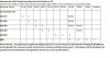
thanks for posting the chart :mrgreen: its bound to be rather useful as a reference to many guys reading thru the thread
Strictly Attitude said:
CHECK THIS OUT!
Checking Distributor Timing
A Winston Cup Engine Builder Shows You How To Get Maximum Power
http://www.circletrack.com/howto/1842_i ... rformance/
Hang out at any race shop or racetrack for a while and you'll see somebody setting the ignition timing on an engine. Some guys do it with the engine idling away, others with the engine screaming past 6,000 rpm. Both ways will set the spark advance, but is it a setting that will help the engine achieve its maximum amount of power? From my experience building race engines for more than 25 years, I have learned a lot about what helps an engine make horsepower and what doesn't. Timing that lights the air/fuel mixture at the ideal point in the cycle can make a big difference in the total power output of your race engine.
When describing ignition timing, many racers use phrases like "I put 30 degrees of lead in it" without understanding what this represents. Ignition is the point at which a high-voltage, low-amperage charge is sent to the spark plug, bridging the gap between the electrode and wire, and igniting the air/fuel mixture. This moment is measured in crankshaft degrees before the piston reaches top dead center (TDC). Most engine builders set the timing based on the No. 1 cylinder, assuming the rest of the cylinders will also fire at that point before TDC (BTDC). The first thing we should all understand is that making any assumptions when building and tuning an engine leads to problems. Timing should be checked for its initial accuracy on all of the cylinders.
We all need to understand that the time it takes for a constant air/fuel mixture to combust does not change, even when the engine speed increases. Therefore, the spark that is activated needs to be advanced as rpm increases, so that the combustion occurs at the optimal time to push the piston down the cylinder. This is why ignition systems have an advance system built-in. On street cars, a vacuum-advance and centrifugal-advance system are used. The vacuum advance increases timing as the load on the engine increases. The centrifugal advance adds advance until about 3,000 rpm to keep the combustion process in time with the piston location.
On race cars, we aren't really loading the engine at low rpm, so the vacuum system is eliminated. In Winston Cup, most cars don't use a centrifugal advance, as this can sometimes not work properly. Street Stock racers will often keep the centrifugal advance on the ignition because the stock starters can't turn over the engine. But racers who can use a gear reduction starter can lock the ignition timing at one setting and fire the engine with no problems. Distributors with a centrifugal advance should be checked on a distributor machine to ensure they are at full advance by 3,000 rpm (engine rpm, not distributor rpm).
It is critical, when you are building your engine or when your engine builder does it, that the harmonic balancer timing marks and the timing pointer are located properly. If the No. 1 piston is actually at TDC, but the timing pointer shows 5 crank degrees before TDC, you could set the ignition advance to a spec set by the engine builder and put the engine into detonation or pre-ignition. Both of these conditions can lead to parts failures.
Here at Team Sabco, there are many tolerances we check when assembling an engine, such as the cam endplay and other parameters. For more on these checks, see the pictures and captions to understand why and how we perform these steps. They make a difference, which is why we do them.
The other step we take is to check the timing on the engine while we're building it. To do this, we set the No. 1 piston at TDC with a piston stop, install the harmonic balancer and timing pointer (if it's removable), and read the timing. We use adjustable pointers, but if you have a stamped timing-chain cover and indicator welded on, you can bend the indicator. If it needs to move considerably, grind it off and weld it back on in the appropriate location.
This is time-consuming, but getting everything properly located while the engine is being built will remove all the mystery when having to set the timing later.
When the engine is together and running, we like to check the distributor to see if each cylinder has the same amount of ignition timing. The way we do it is to set the timing at 30 degrees total advanced on the No. 1 cylinder, with the engine at a predetermined rpm. We use a timing belt on our engines and know the belt will stretch at high rpm, retarding the cam and therefore the ignition, so we check the timing at a relatively high rpm, such as 5,500 rpm. This can be dangerous and is really needed only if the engine has a timing belt. On an engine with a timing chain, it is recommended to check the timing at no higher than 4,000 rpm.
Read each cylinder for ignition timing at the same rpm. Chart all of this information on a piece of paper, as you'll want to eventually adjust each cylinder to the baseline 30 degrees, and you'll forget what each cylinder's timing was if it's not written down. You'll be surprised how much the timing varies from cylinder to cylinder.
To tune the engine, you need to have the timing constant throughout the firing order. In order to do this, there is a certain amount of math to understand. First, you must realize that the damper has 360 degrees marked as zero degrees, and that, in rotation, we count down from 360 degrees to zero on the balancer--not up. Second, realize that the ignition fires 30 degrees BTDC every 90 degrees throughout the firing order. With a 360-degree rotation, that means a piston is reaching TDC at zero-, 270-, 180-, and 90-degrees crank rotation as marked on the harmonic balancer. If we add the ignition advance, we see that a spark plug fires at 30-, 300-, 210-, and 120-degrees rotation of the crank. It is still 30 degrees BTDC on each cylinder, but we need to think of it in crank-rotation degrees to tune the ignition timing. We use 30-degrees ignition advance as a baseline because it minimizes the complexity of the math. Here is a way to simplify it. These cylinders will use the same mark on the harmonic balancer: Cylinders 1 and 6 will use 30 degrees, 8 and 5 use 300 degrees, 4 and 7 use 210 degrees, and 3 and 2 use 120 degrees.
As we're checking the timing on each cylinder, we write down what it actually is on each cylinder. Then we go back and adjust the reluctor tangs on the MSD distributor with our custom tool. To make sure we bend the correct reluctor tang in the proper direction, we locate the rotor on the No. 1 cylinder and mark the reluctor tang in front of the pickup. That way, when we pull the cap off to adjust the No. 6 cylinder, we just count four tangs over from the No. 1 reluctor tang.
To advance the ignition on any cylinder, the tang is bent toward the direction of rotation; to retard it, the tang is bent opposite the direction of rotation. On a stock-type HEI ignition, you can't really alter the timing per cylinder. On a points distributor, you can file the point one way or another, but it is much more difficult than working with the MSD.
Be very conservative as you get used to what it takes in the adjustment of this. In the beginning, work slowly with one cylinder until you figure out how to get the desired timing. You will develop a "feel" for it with practice. The best way to determine the optimum timing for an engine is really on a dyno. One way to minimize the cost of this procedure would be to do the tuning of the ignition timing with the engine in the car or on a run-in stand. Then, once all the cylinders have the same ignition timing, go to the dyno to determine the optimal overall ignition timing.
In the end, after you've taken all these steps, you'll know that the timing mark is located correctly on your engine, that the ignition is the same throughout the engine, and what the timing really is, because it will be much more stable on the pointer. Best of all, you should have some more power to play with on the track.
This is how the ignition timing is set on our engines. We use the brightest timing light available--the French Grimes Winston Cup timing light. It's made in America, is rebuildable, and costs less than $200.
Here is a basic set of curves showing what ignition timing does to combustion-chamber pressure. The pressure curve is critical to getting the most power from each combustion cycle. Curve 1 shows a smooth, deep curve while Curve 2 represents too much ignition-timing advance showing pressure spikes, probably caused by uneven combustion, which could lead to parts failure. Curve 3 represents ignition timing that has too much retard in it and is relatively flat, resulting in lost power. Ideal timing results in good power.
The machine work done on a race engine can change the center-to-center dimension between the crank and the camshaft. To make sure our timing belts are the proper length for the application, we test them on this fixture. If you use a timing chain, they can be ordered for various dimensions between the cam and crank. This is important because too much play in the belt or chain will allow the timing to vary considerably.
The endplay of the cam should be minimal, as the movement of the cam back and forth during engine operation changes the way the gears mesh between the cam and distributor, which alters the total ignition timing in the engine. Consult your engine builder on the recommended endplay clearance.
To set the cam endplay, the end plate on the two-piece cover for the Jesel beltdrive is installed with various shims. If you have a timing chain with a one-piece cover, you can use a cam button to limit endplay.
We built a distributor-length measuring tool because, if the distributor gears sit too low or high on the cam gears, the gears can wear irregularly, and the ignition timing can vary or a failure can result. Once the intake is on the assembled engine, the tool is dropped down into the distributor hole and the sliding locator set on the rod. Then, that distance is measured against the distributor. On the MSD distributor, the collar can be adjusted up or down as needed, and on a factory-type distributor, shims can be used if the distributor needs to be located higher in the block. Also, with a stock wet-sump oil pump, check the oil-pump drive rod length to make sure the distributor is not pushing directly on the oil-pump gear.
The endplay of the distributor shaft should be checked, as too much of this will allow the ignition timing to vary. On our MSD distributors, we set the endplay at 0.008 to 0.010 inch, using various shims between the housing and a 0.006-inch bigger od bronze gear pinned to the end of the shaft, to reduce the amount of clearance between the distributor and cam gear.
We set the timing at 30 degrees on the No. 1 cylinder and recorded the timing on the other cylinders. For instance, on the No. 8 cylinder, the timing would show up as 300 degrees on the harmonic balancer. Since No. 8 comes after No. 1 in the firing order, TDC for that cylinder would be 270, and the ignition will fire 30 degrees before 270, which is 300 degrees. Often, the timing is off by a few degrees, so after recording all of the timing data for the engine, I'll go back and tune the timing with this Sabco-built tool. We tweak the tangs on the MSD reluctor to advance or retard certain cylinders. Adjusted in small increments for each cylinder, this can improve performance considerably.
Once all the tolerances are set on the meshing components, the next step is to locate the timing pointer. Use a piston-stop on the block, and check the pointer for all the cylinders. We set the timing for each cylinder and start gathering data at this point in order to know where everything is. Remember, don't assume anything.
Using an ATI or similar harmonic balancer, with the crank degrees clearly marked on it, will allow concise measurements. MSD, Mr. Gasket, and other companies make "timing tapes," which are just that--crank degrees on a tape that you attach to a harmonic balancer. Both work fine, but check everything!
Its Interesting to see our posts Rick & Grumpy from 1 year ago.
I always try & get the fastest advance curve possible on pump gas Rick.
Pontiac & Olds V8 Seem to tolerate real fast advance curves.
All in by 900-1200 RPM.
I have real lightweight advance springs from early Mopar distributors I robbed them from.
A few times I brazed a small glob of brass brazing rod pn the advance weights .
Add a little mass in grams. Speed up advance.
Different ways to skin the Cat.
I never use the vacuum advance can.
Leave it unhooked. Its for fuel economy purposes.
Vertex Magnetos don't use Advance springs.
I have custom filed by hand different ramps in stacked plates to get fast advance.
Or even better lock it out for full advance for Race use.
Leave Mag switch off. Crank engine & electric fuel pump on. Dtab the gas 2 times. Flip Mag switch on.
455 Pontiac Roars to Life.
there is , without any doubt, at least... theoretically, long bloody scratch marks on the pavement,
as I'm dragged kicking and screaming into the computer/digital era,
but you really can,t dispute the facts and the facts are,
that there are now ways to set the car engine ignition timing that were just not all that easy to duplicate with purely mechanical controlled ignition advance curves.
between knock sensors that see and react to detonation, coil on individual spark plug ignition, crank sensors etc.
and computer controls that allow you to select and set the degree of ignition advance,
and sensors that read the fuel/air ratio hundreds of times a second, and allow the injector pulse duration to be adjusted to compensate if you have the correct matching software,
at every few hundred rpm check points, its no longer a question that if you select the correct components you can pull power levels from engines that were previously very difficult to achieve.
The CB Timing control is neat Grumpy.
Vertex had a prototype in the works similar for thier Mags back in 2004.
I wanted bad..project got dropped.
Still have the sales Flyer.
MSD has the 12 & 44 Pro mag seriers that do all that.
$5k & 10 k still.
Funny thing is with E85 and Turbos Timing control is not critical.
Just give the timing it wants and done.