_72 said:Tearing down my 454 and measured the rotating assembly drag to be ~28 ft-lbs. Found one source that said it should be 35-40 ft-lbs, but no mention how to interpret a number that is outside that spec. Just means my motor needs a rebuild which I'm planning on anyway?
Thanks!
:cheers:
on a newly rebuilt engine the SHORT BLOCK (no heads installed) and with the bearings and cylinder bores oil coated, it should require LESS than 40ft lbs to get rotating and less to keep it rotating, a crank ALONE installed in the correctly tightened main caps should require LESS than 10 lbs to start rotating and far less to keep spinning.
on a racing engine the crank alone can easily be spun in the main bearings with your fingers and over about 25-28 lbs resistance when using low drag rings usually indicates a problem
a used engine will develop a bit looser clearances and require LESS force to rotate after the heads are removed.
yes having an accurate torque wrench is mandatory when you build an engine, yes having the piston to bore clearance, ring end gap and bearing clearances correct helps a great deal, and yes low tension rings DO tend to reduce the resistance to rotation, and yes, some assembly lubes DO make the engine a bit harder to start the rotation.
obviously a slightly bent crank, inconsistent bearing clearances, non-round crank journals , rough polish surfaces on journals or a block that needs to be line honed or a bent cam or tight cam bearing journals or improper bearing clearance or dry bearing surfaces tend to increase resistance.
IF your engine resists rotation to a higher torque load rate
FIND OUT WHATS BINDING BEFORE PROCEEDING FURTHER
obviously if the engine locks up at some point in the rotation, while you test to find out why the engine won't easily rotate a full 360 degrees,
but allows you too reverse directions and spin it almost the full 360 degrees before it again locks, preventing full rotation your engines got some part physically binding, preventing your rotation, , its most likely sone failed part like a broken piston, or valve train component, forcing it will result in DAMAGE, thus you must pull the head(S) and maybe the oil pan for a closer inspection, before you proceed and potentially cause more damage
READ THROUGH THIS LINKED THREAD
http://garage.grumpysperformance.com/index.php?threads/precision-measuring-tools.1390/#post-52469
http://garage.grumpysperformance.co...tion-of-crank-durring-short-blk-assembly.852/
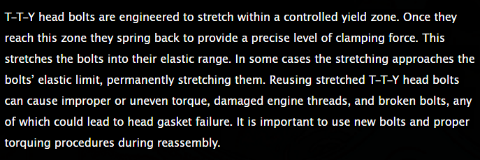
https://www.felpro.com/parts/engine-repair/head-bolt-sets.html
\READ THRU THESE LINKS AND ASK QUESTIONS IF YOUR NOT 100% CERTAIN OF THE ANSWERS
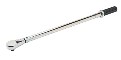
youll need a good quality torque wrench
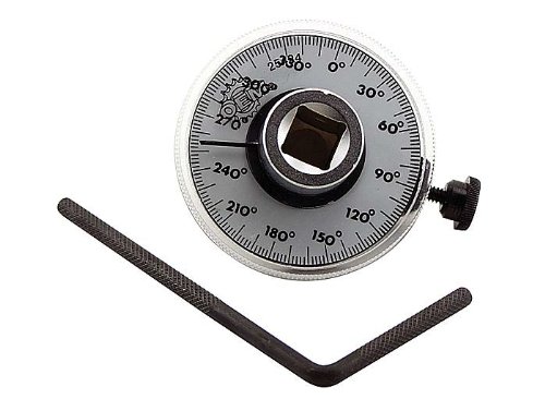
and a torque angle gauge
shop carefully the exact same set of mics from the same company can cost $270-$900 depending on where you buy the set
https://www.greatgages.com/products...MIyYigxdnA1QIVU2p-Ch1Z7wX8EAQYASABEgLrvvD_BwE
Directions for crankshaft grinding and polishing
Crankshaft journal surfaces should be ground and polished to a surface finish of 15 micro inches roughness average Ra or better. Journals on highly loaded crankshafts such as diesel engines or high performance racing engines require a finish of 10 micro inches Ra or better.
The above is a simple straight forward specification which can be measured with special equipment. However, there is more to generating a ground and polished surface than just meeting the roughness specification. To prevent rapid, premature wear of the crankshaft bearings and to aid in the formation of an oil film, journal surfaces must be ground opposite to engine rotation and polished in the direction of rotation. This recommendation and examination of the following illustrations will help make the recommendation more clear.
Metal removal tends to raise burrs. This is true of nearly all metal removal processes. Different processes create different types of burrs. Grinding and polishing produces burrs that are so small that we can't see or feel them but they are there and can damage bearings if the shaft surface is not generated in the proper way. Rather than "burrs", let's call what results from grinding and polishing "microscopic fuzz." This better describes what is left by these processes. This microscopic fuzz has a grain or lay to it like the hair on a dog's back. Figure 1 is an illustration depicting the lay of this fuzz on a journal. (Note: All figures are viewed from nose end of crankshaft.)
btw that innitial resistence ,too rotation, to get the crank assembly rotating in the bearings and rings dragging accross the cylinder bore surfaces,
as the parts come up on the combined, wedge/lubricant bearing surfaces ,
when it breaks loose and spins easier, is closely related to and changes with the type of assembly lube you selected to use.
the components sellected and clearances and contact surface smoothness and consistency,
every assembly will have minor differences, as will every different lubricant, even temperature will change the results.
resistance to rotation, of crank durring short blk assembly
Ok youve just installed your crankshaft in the engine block, with new main bearings and everything's well coated with assembly lube,and oil, and youve torqued down the main caps to spec. in at least three stages, and then gone back and rechecked the studs or bolts per the manufacturers...
garage.grumpysperformance.com
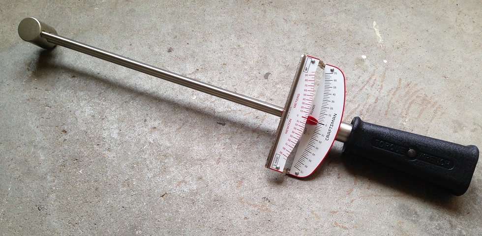
that's why you'll need a torque beam deflection torque wrench to check that
https://www.amazon.com/Presa-Drive-...ocphy=9012039&hvtargid=pla-669567243785&psc=1
The direction in which a grinding wheel or polishing belt passes over the journal surface will determine the lay of the micro fuzz.
In order to remove this fuzz from the surface, each successive operation should pass over the journal in the opposite direction so that the fuzz will be bent over backward and removed. Polishing in the same direction as grinding would not effectively remove this fuzz because it would merely lay down and then spring up again. Polishing must, therefore, be done opposite to grinding in order to improve the surface.
In order to arrive at how a shaft should be ground and polished, we must first determine the desired end result and then work backwards to establish how to achieve it. Figure 2 depicts a shaft turning in a bearing viewed from the front of a normal clockwise rotating engine. The desired condition is a journal with any fuzz left by the polishing operation oriented so it will lay down as the shaft passes over the bearing (Figure 2).
The analogy to the shaft passing over the bearing is like petting a dog from head to tail. A shaft polished in the opposite direction produces abrasion to the bearing which would be like petting a dog from tail to head. To generate a surface lay like that shown in Figure 2, the polishing belt must pass over the shaft surface as shown in Figure 3.
The direction of shaft rotation during polishing is not critical if a motorized belt type polisher is used because the belt runs much faster than the shaft. If a nutcracker-type polisher is used, then proper shaft rotation must be observed (Figure 4). Stock removal during polishing must not exceed .0002" on the diameter.
Having determined the desired surface lay from polishing, we must next establish the proper direction for grinding to produce a surface lay opposite to that resulting from polishing. Figure 5 shows the grinding wheel and shaft directions of rotation and surface lay for grinding when viewed from the front or nose end of the crankshaft. This orientation will be achieved by chucking the flywheel flange at the left side of the grinder (in the headstock). Achieving the best possible surface finish during grinding will reduce the stock removal necessary during polishing.
The surface lay generated by grinding would cause abrasion to the bearing surfaces if left unpolished. By polishing in the direction shown in either Figure 3 or 4, the surface lay is reversed by the polishing operation removing fuzz created by grinding and leaving a surface lay which will not abrade the bearing surface.
Nodular cast iron shafts are particularly difficult to grind and polish because of the structure of the iron. Nodular iron gets its name from the nodular form of the graphite in this material. Grinding opens graphite nodules located at the surface of the journal leaving ragged edges which will damage a bearing. Polishing in the proper direction will remove the ragged edges from these open nodules.
All of the above is based on normal clockwise engine rotation when viewed from the front of the engine. For crankshafts which rotate counterclockwise, such as some marine engines, the crankshaft should be chucked at its opposite end during grinding and polishing. This is the same as viewing the crank from the flanged end rather than the nose end in the accompanying figures.
Unlike many engine bearings available today, Clevite engine bearings utilize a superior Clevite TriMetal™ material design. Stamped "Clevite®," this design incorporates the strength of a copper-lead alloy layer on a steel back and finally, a precision electroplated white metal "babbitt" third layer. TriMetal™ is an ideal bearing design producing good to excellent characteristics when judged for conformability, embedability, slipperiness and fatigue resistance.
We constantly monitor the function and operation of our full line of bearings, staying in touch with any changes or developments that new engines may require. And that translates into bearings that are better for your engine. If you're looking for the engine bearings that set the standards, specify Clevite®. Because you won't settle for second best.
http://garage.grumpysperformance.co...tion-of-crank-durring-short-blk-assembly.852/
http://garage.grumpysperformance.co...g-and-installing-connecting-rods-pistons.247/
http://garage.grumpysperformance.com/index.php?threads/connecting-rod-strength-h-vs-i-beam.1168/
http://garage.grumpysperformance.com/index.php?threads/precision-measuring-tools.1390/
http://garage.grumpysperformance.com/index.php?threads/rotating-assembly-bearings.9527/
http://garage.grumpysperformance.co...ng-and-basic-piston-ring-info-youll-need.509/
http://garage.grumpysperformance.com/index.php?threads/installing-rings-in-piston-grooves.9490/
http://garage.grumpysperformance.co...guess-on-clearances-and-journal-surface.9955/
http://garage.grumpysperformance.co...kshaft-and-connecting-rod-compatability.9320/
Last edited by a moderator: