And what's your point ???He Likes Pontiac V8 also !
You are using an out of date browser. It may not display this or other websites correctly.
You should upgrade or use an alternative browser.
You should upgrade or use an alternative browser.
383 rebuild - old dyno results & new cam ideas
- Thread starter Drew Pedersen
- Start date
keep in mind when viewing the head flow graph posted above , that there are other , important factors in any engine combo,
head flow is critical but it must match the other parts selected,
those brodix 200 heads are known to make good power, now looking at the graph, you might think, they can,t compete,
but if your intake manifold only flows lets say 260 cfm they may be the hot ticket!
its not the individual part but the total combo that maters,
few dual plane carburetor intakes exceed 270 cfm in individual runner flow
I know you are posting to serve the masses, but then I can't tell if you are disagreeing
with my comments. Hard to have a discussion when I don't know what you are
commenting about.
Maniacmechanic1
solid fixture here in the forum
Everything is application specific.And what's your point ???
No one size fits all.
Maniacmechanic1
solid fixture here in the forum
Grumpy is using Smokey Yunick Apology along with his own personal experiences.I know you are posting to serve the masses, but then I can't tell if you are disagreeing
with my comments. Hard to have a discussion when I don't know what you are
commenting about.
Im not in any way dis-agreeing with you, ,and your 100% correct that almost 100% of the answers I post,
are directed at anyone reading the thread, unless I start the answer with a specific name.
the two main reasons I posted that were
(1) I occasionally see guys buy ,a few very expensive components and mis-match them, too other far lower quality parts,
yet they don,t grasp the concept of that (weakest link in the chain)
I can,t even count the number of guys I've seen slap some killer cam like this
https://www.summitracing.com/parts/lun-10120412lk
and a nice tunnel ram intake they got at a local swap meet,
https://www.summitracing.com/parts/edl-7110/overview/
on a stock 350 with 8:1 compression and stock smog heads,
and a stock exhaust system,with 2" pipes, restrictive mufflers,
and a car with an auto trans,like a older chevelle or impala,
stock converter stall, and a 2.87:1-3.07:1 rear gear.
then they stop over and ask me to tune it
, "it just does,t seem to run as well as I expected it too"
(2) Ive built at least a dozen 383-406 engines with those brodix heads ,
most made close too or exceeded 500 hp
and had very good lower and mid rpm torque, and for the cost outlay
(at the time, and that was over several years, they cost less than $875--$1050 a set)
https://www.jegs.com/i/Brodix/158/1021001/10002/-1
in fact they used too sell for less than 65% of what the AFR heads sold for and
produced similar power in most cases
I feel they were then and are an outstanding value
Maniacmechanic1
solid fixture here in the forum
500 Hp is all that can be expected and be in the safe zone on pump gas Grumpy.
No sense pursuing limits .
Not drag racing most with a Sbc.
Better options for other engines as we both know 1st hand.
No sense pursuing limits .
Not drag racing most with a Sbc.
Better options for other engines as we both know 1st hand.
Grumpy,
What I'm trying to get at is, do you agree/disagree with my statement for the sharp corner in the TQ curve. Does
the sharp corner at 4500 rpm and the TQ curve correlate with the corner in the intake flow at .400 lift. I'm starting
to wonder if they are NOT related. There are two corners in the TQ curve, only one corner in the flow curve.

a.jpg")
The two flow files for AFR 195 Street and AFR 195 Ported both have nearly identical flow and
the same sharp corner at .400 inches of lift. I have to wonder if this doesn't explain somewhat
the sharp corners in the HP/TQ graphs. After .400 lift, then the ported head shows better flow.
What I'm trying to get at is, do you agree/disagree with my statement for the sharp corner in the TQ curve. Does
the sharp corner at 4500 rpm and the TQ curve correlate with the corner in the intake flow at .400 lift. I'm starting
to wonder if they are NOT related. There are two corners in the TQ curve, only one corner in the flow curve.
Drew Pedersen
Member
Indycars,
I am leaning towards the two not being related but that is based on more of a "gut" feeling at the moment, I don't have any concrete evidence or theory to back up my opinion though - only speculation. Your statement has sparked a few questions for me that I haven't thought of before:
- Is flow affected by RPM? i.e. - if a head/intake combo flows 250 CFM @ peak valve lift of the cam being used, and the engine is capable of using 250 CFM each intake cycle, will the head/intake flow 250 CFM at idle and at higher RPM's, or is the flow rate at slower engine speeds less?
- Could the air flow of the head with the sharp corners (steps) in flow rates be creating a "pulse" affect with the air flow increasing (valve opening) then decreasing (valve closing) during the intake cycle? If so could the "pulse" cause a dramatic step in HP/TQ numbers at specific RPM's due to pulse frequency?
On another note: During the planning phase of this build I compared head flow numbers of most of the leading aluminum offerings at the time (2011). I looked at average flow under .500 lift, peak numbers, valve diameter , valve springs included, etc. but never once thought of mapping the flow data out on a graph . Thank you for the idea, if I ever swap heads I'll be sure and include that in my research. I also never considered the intake limiting the potential flow of the heads. When Grumpy made the statement about the Brodix heads it suddenly hit me that my heads flow 290 CFM......but what does my intake flow?
I am leaning towards the two not being related but that is based on more of a "gut" feeling at the moment, I don't have any concrete evidence or theory to back up my opinion though - only speculation. Your statement has sparked a few questions for me that I haven't thought of before:
- Is flow affected by RPM? i.e. - if a head/intake combo flows 250 CFM @ peak valve lift of the cam being used, and the engine is capable of using 250 CFM each intake cycle, will the head/intake flow 250 CFM at idle and at higher RPM's, or is the flow rate at slower engine speeds less?
- Could the air flow of the head with the sharp corners (steps) in flow rates be creating a "pulse" affect with the air flow increasing (valve opening) then decreasing (valve closing) during the intake cycle? If so could the "pulse" cause a dramatic step in HP/TQ numbers at specific RPM's due to pulse frequency?
On another note: During the planning phase of this build I compared head flow numbers of most of the leading aluminum offerings at the time (2011). I looked at average flow under .500 lift, peak numbers, valve diameter , valve springs included, etc. but never once thought of mapping the flow data out on a graph
. Thank you for the idea, if I ever swap heads I'll be sure and include that in my research. I also never considered the intake limiting the potential flow of the heads. When Grumpy made the statement about the Brodix heads it suddenly hit me that my heads flow 290 CFM......but what does my intake flow?short answer, yes head flow and torque are closely related
your gentlemen might want to read this and play with calculators
http://garage.grumpysperformance.com/index.php?threads/port-speeds-and-area.333/#post-72826
related info
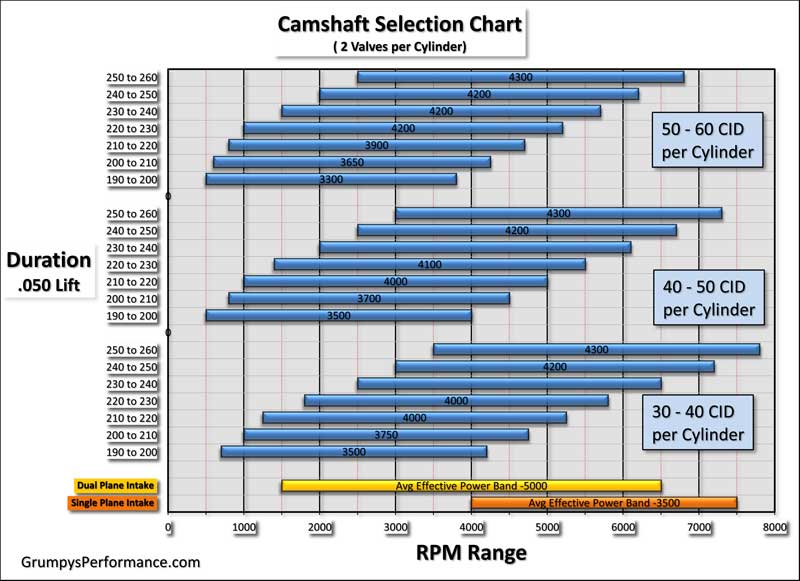
USE THE CALCULATORS to match port size to intended rpm levels... but keep in mind valve lift and port flow limitations[/color]
http://www.wallaceracing.com/runnertorquecalc.php
http://www.wallaceracing.com/ca-calc.php
http://www.wallaceracing.com/area-under-curve.php
http://www.wallaceracing.com/chokepoint.php
http://www.wallaceracing.com/header_length.php
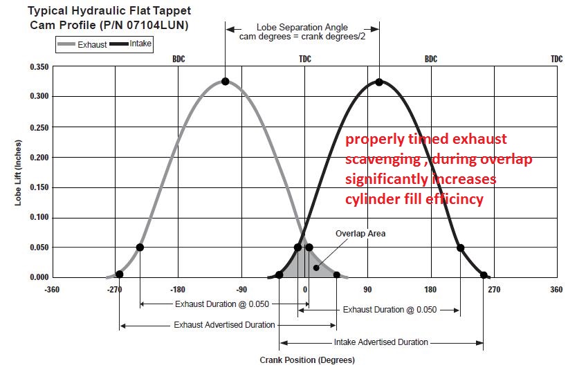
keep in mind
properly matching,
cam timing,
engine displacement,
compression,
and header design
has a huge effect on intake port flow efficiency
your gentlemen might want to read this and play with calculators
http://garage.grumpysperformance.com/index.php?threads/port-speeds-and-area.333/#post-72826
related info
USE THE CALCULATORS to match port size to intended rpm levels... but keep in mind valve lift and port flow limitations[/color]
http://www.wallaceracing.com/runnertorquecalc.php
http://www.wallaceracing.com/ca-calc.php
http://www.wallaceracing.com/area-under-curve.php
http://www.wallaceracing.com/chokepoint.php
http://www.wallaceracing.com/header_length.php
keep in mind
properly matching,
cam timing,
engine displacement,
compression,
and header design
has a huge effect on intake port flow efficiency
Last edited:
But can one infer that flow at .400 lift and the TQ at 4500 rpm are related???short answer, yes head flow and torque are closely related
Maniacmechanic1
solid fixture here in the forum
I always look at the average Flow curve.
Most important the Exhaust to Intake Ratio present...the Mean Average.
Race you need .75-.80.
Example Pontiac RAIV 1970 Year does it bone stock.
Factory street race engine like a Chevy L88 427 Corvette.
The engineers dabbled intentional for optimal E/I ratio to meet different driving goals.
Many aftermarket heads are terrible E/I.
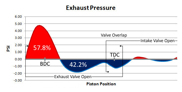
Irrespective of rpm, valve lift remains consistent, with the cam and rocker ratio, used,
but both intake and exhaust flow changes with both rpm and exhaust scavenging efficiency
and both that changes with cam timing selected,
no you can,t directly infer .400 lift alone has predictable effects 4500 rpm flow
there will be a rather narrow rpm band of about 1500 rpm-2000 rpm
that will vary with displacement,compression and other factors
The rpm where headers scavenging will be much more efficient , in a narrow rpm range,
due to more effective cylinder scavenging
in an ideal build you've maxed exhaust scavenging of the cylinders in the intended rpm/power band.
- Is flow affected by RPM? i.e. - if a head/intake combo flows 250 CFM @ peak valve lift of the cam being used, and the engine is capable of using 250 CFM each intake cycle, will the head/intake flow 250 CFM at idle and at higher RPM's, or is the flow rate at slower engine speeds less?
When you say the head flows 250 cfm, that is a steady state flow rate. The engine in reality is anything
but steady state flow. If the engine was flowing the same at idle, it would not be idling. As rpm rises, so
does the air flow thru the engine up to a point. Just like in the flow curves above, the flow tapers off at
higher rpm until there is no further increase.
- Could the air flow of the head with the sharp corners (steps) in flow rates be creating a "pulse" affect with the air flow increasing (valve opening) then decreasing (valve closing) during the intake cycle? If so could the "pulse" cause a dramatic step in HP/TQ numbers at specific RPM's due to pulse frequency?
No, I don't think so. A pulse is created when the flow hits a change in cross sectional area. As in when the
flow hits the outlet of the primary tube in the collector. It's also the reason we see Stepped Headers.
Maniacmechanic1
solid fixture here in the forum
That all important 5th cycle.Irrespective of rpm, valve lift remains consistent, with the cam and rocker ratio, used,
but both intake and exhaust flow changes with both rpm and exhaust scavenging efficiency
and both that changes with cam timing selected,
no you can,t directly infer .400 lift alone has predictable effects 4500 rpm flow
there will be a rather narrow rpm band of about 1500 rpm-2000 rpm
where headers scavenging will be much more efficient due to more effective cylinder scavenging
in an ideal build you've maxed exhaust scavenging of the cylinders in the intended rpm/power band.
Cylinder scavenging.
Obtain 100 % VE or greater on the street and stay in safe Rpm zone.
Not easy to do.
Pump gas also detonation free .
Maniacmechanic1
solid fixture here in the forum
Crower Stack injection and Hilborn are best Grumpy N/A.
Maniacmechanic1
solid fixture here in the forum
I call them Finate Amplitude Waves Grumpy as you know.
Danger Zone cams make it easy.
Learned not to go there.
Too many issues that way Small Block Chevy and what most guys have for hard engine parts.
Need safe zone.
Danger Zone cams make it easy.
Learned not to go there.
Too many issues that way Small Block Chevy and what most guys have for hard engine parts.
Need safe zone.
Id also point out that any particular rpm is passed through,
in most cases in far less than a second in any real use,
only a dyno will hold the engine at one particular rpm,
yes you might cruise at a set rpm, but that will generally be at,
considerably lower than peak power,
especially with over drive geared transmissions commonly in use now.
in an ideal world you gear the car so you maximize the cars ability to operate in,
the most effective part of the engines power band
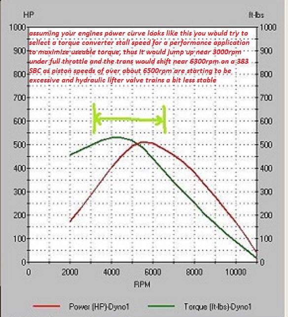
the whole idea of swapping to a higher stall speed torque converter is to allow the engine UNDER LOAD to jump in rpm up into the engines most efficient power range or the most effective part of the torque curve.
the basic object of swapping to a higher stall converter speed is to allow the engine to spend a good deal more time in its most efficient power range without needing to WASTE TIME build rpms slowly up in the lower engine speed ranges where there's a good deal less usable power available
in most cases in far less than a second in any real use,
only a dyno will hold the engine at one particular rpm,
yes you might cruise at a set rpm, but that will generally be at,
considerably lower than peak power,
especially with over drive geared transmissions commonly in use now.
in an ideal world you gear the car so you maximize the cars ability to operate in,
the most effective part of the engines power band
the whole idea of swapping to a higher stall speed torque converter is to allow the engine UNDER LOAD to jump in rpm up into the engines most efficient power range or the most effective part of the torque curve.
the basic object of swapping to a higher stall converter speed is to allow the engine to spend a good deal more time in its most efficient power range without needing to WASTE TIME build rpms slowly up in the lower engine speed ranges where there's a good deal less usable power available
Maniacmechanic1
solid fixture here in the forum
A pulse is created when the Intake valve closes.
A reverse shock wave finite wave.
It's more powerful than a DB level of a jet engine on take off.
Around 200-400 db.
Imagine tossing a rock into a pond.
Ripples forward then back at you the water.
Floating stick moves forward with Thrust Force.
Same thing happens in a running engine.
Particle movement.
Invisible to the naked eye but it's there.
Called the Kadance theory in past.
Sort of correct.
WW2 Aviation engineers discovered something else was going on inside of the Aviation Warbird engines.
