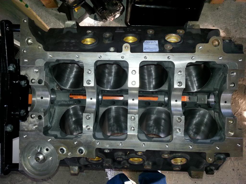
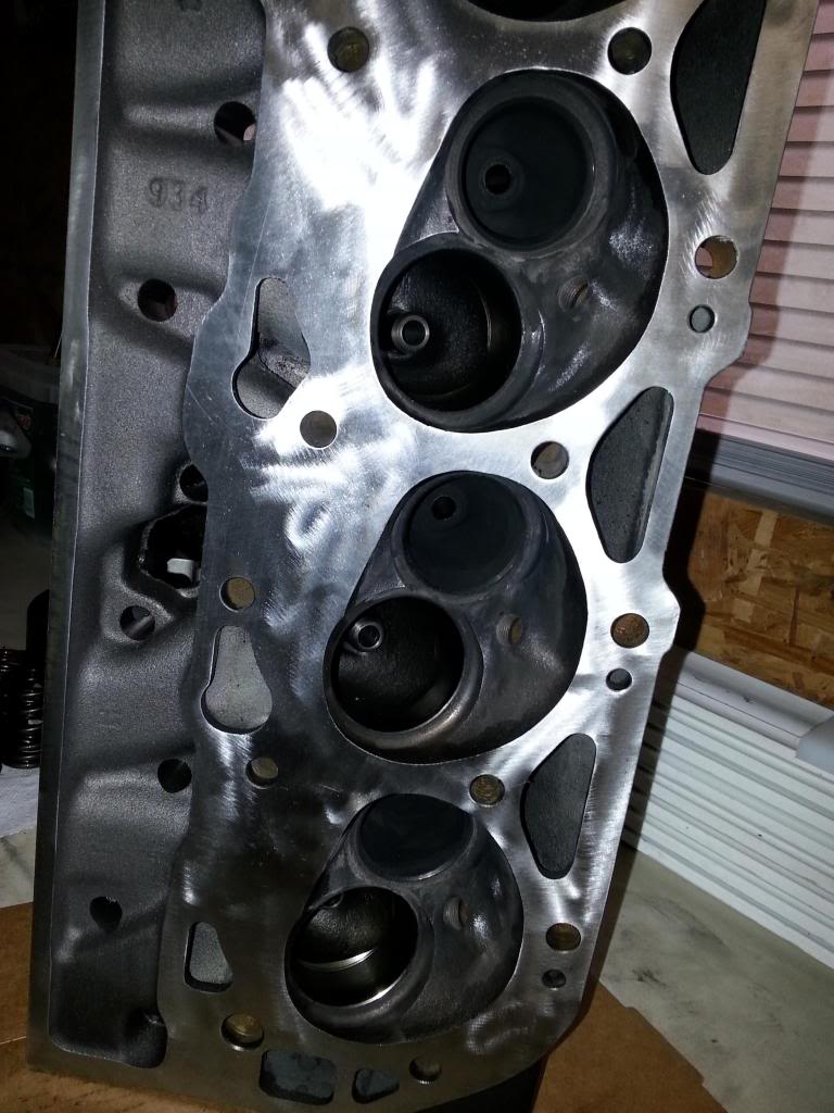
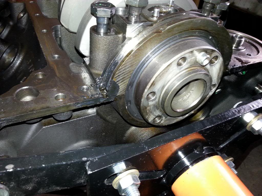
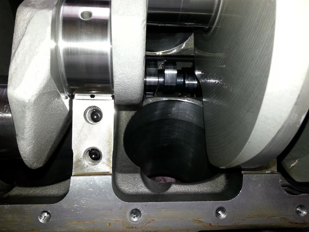
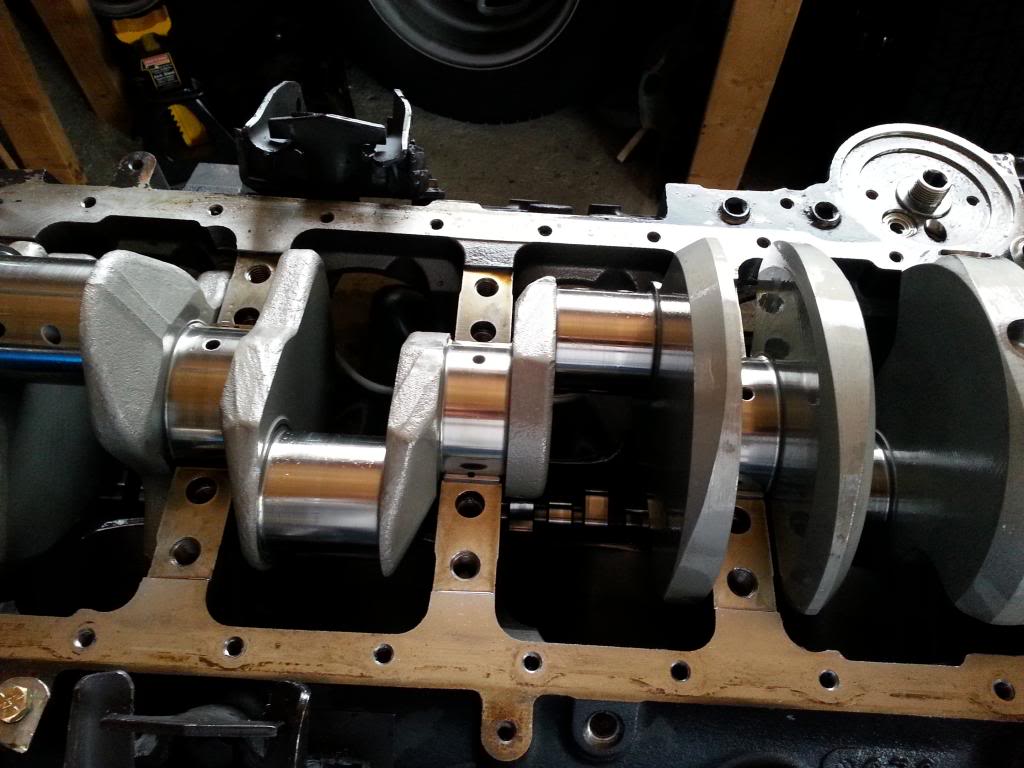
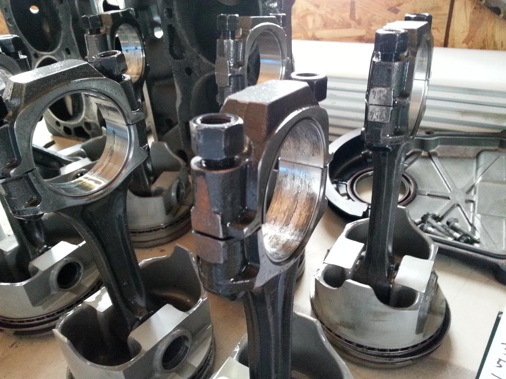
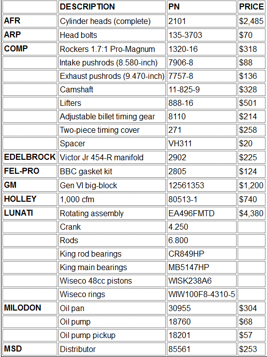
another 496bbc

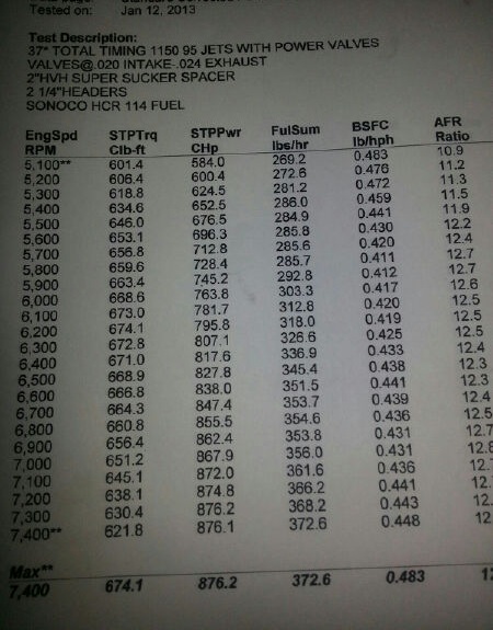
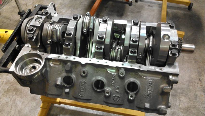
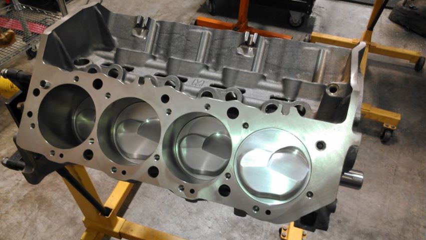
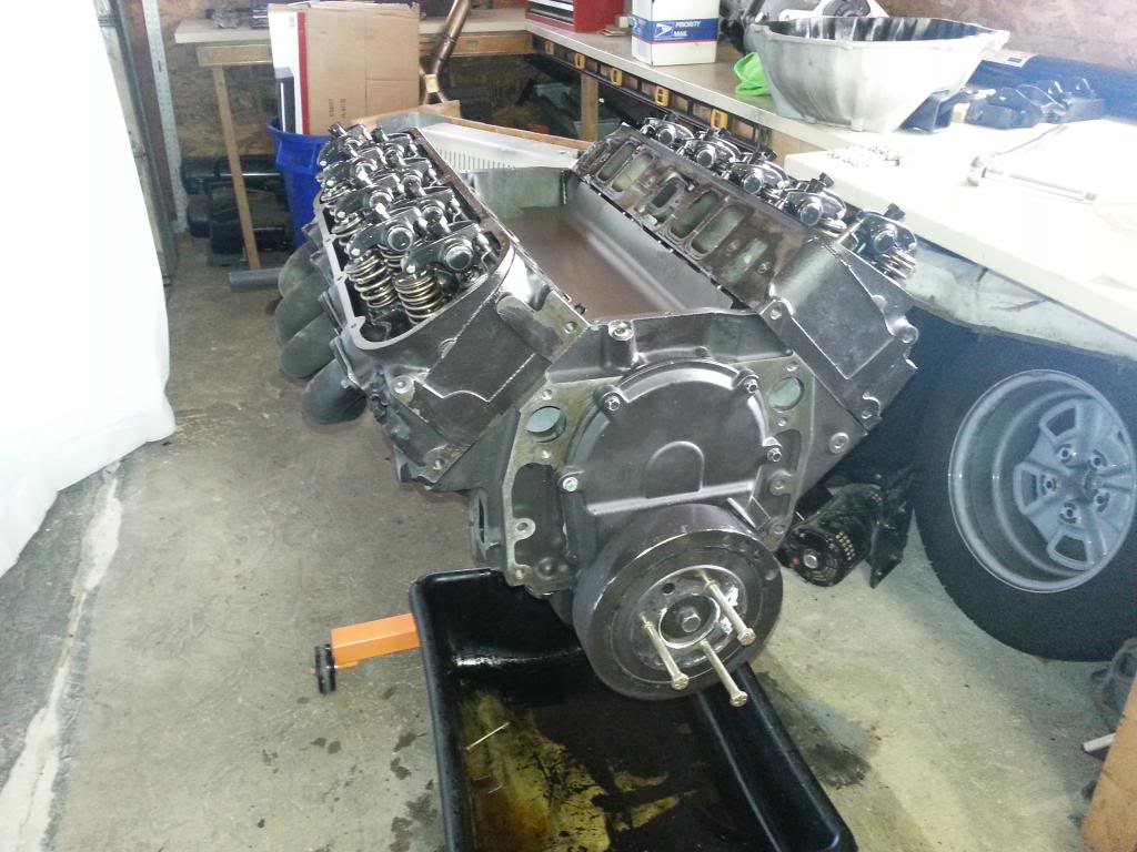
496 BBC 876hp
Thought some of you guys would like to see this.

496 BBC
280/290 799/775 lift, 113 LSA
13.5-1 compression
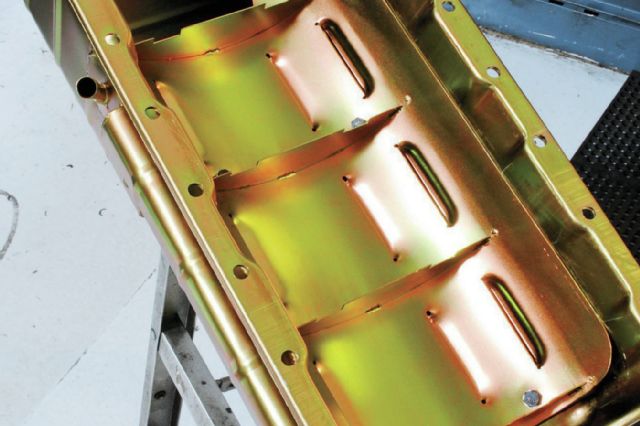
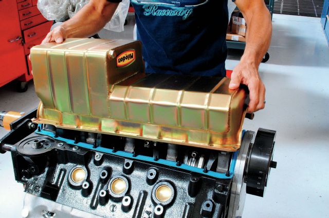
Milodon oil pan
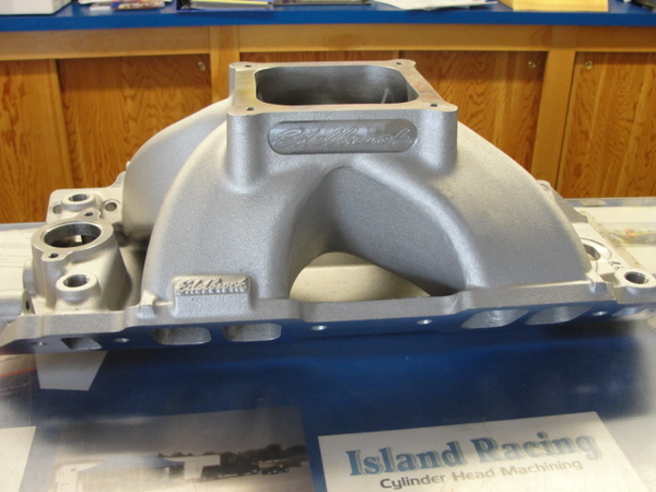
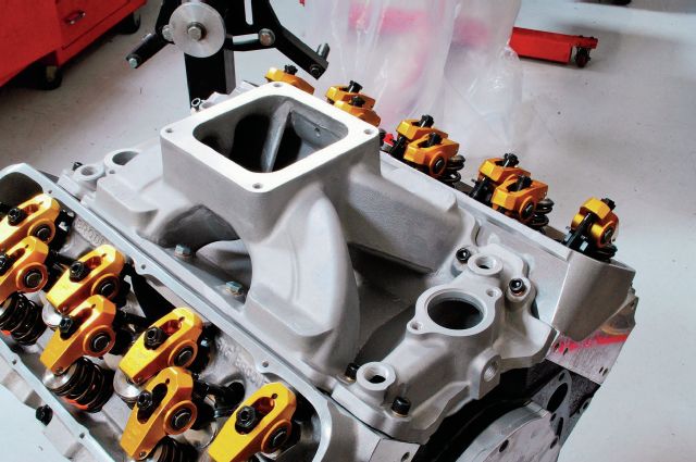
2927 ported manifold
Stock 1050 HP carb
Massaged 335 AFR's cylinder heads
Titanium Valves
dyno9496-1.jpg

http://www.speierracingheads.com/
 
bbcblc1.jpg

bbcblc2.jpg

markvioilp.png


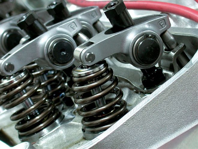
some roller rocker too retainer combo clearance issues cause problems easily solved with beehive springs and smaller retainer diameters
beehivesprcl.jpg

for several years even stock BBC engines ,(the markVI and mark V) as opposed to the (mark IV earlier BBC engines)
also don,t use adjustable rocker arms if your running a stock cam and valve train with stock O.E.M. heads you probably can get by without them,
swap to a higher lift cam and a longer duration and aftermarket heads and better valve strings and in my opinion,
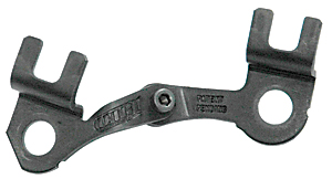
you would be very foolish to build and use a performance BBC engine without adjustable push rod guide plates
what you really should do is order these
Dart 27001230-4 - Dart Pushrod Guideplates

301-27001230-4.jpg


viewtopic.php?f=44&t=2839&p=7344&hilit=adjustable+guide#p7344
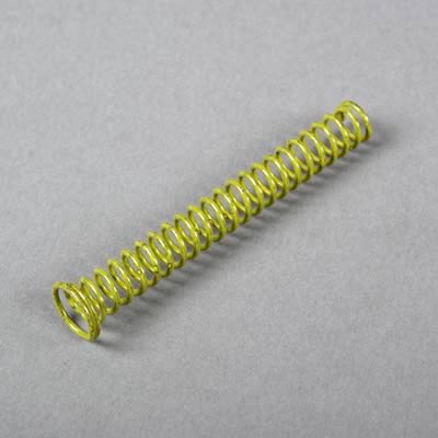
you should NEVER shim an oil pumps pressure relief spring as it may prevent the piston it holds from moving down its bore far enough to allow it to open the bay-pass passage, that allows the pressure on the high pressure side of the oil pump from bleeding off back into the intakes side of the oil pump

oilspring.jpg

Melling_Spring_Specs.jpg

Many pressure relief springs have one end larger than the other end,the spring always mounts with the larger end facing away from the bypass piston, if installed reversed the piston can,t move far enough to completely open the bypass circuit passage and pressures skyrocket, under some conditions

in my opinion , and experience and from lots of G.M. engine, race testing.
theres no need for oil pressure to exceed about 65 psi,
it takes power to spin the oil pump against that extra resistance, it induces extra wear on the distributor and cam gears,
and it does nothing to reduce bearing wear or increase cooling on the bearing surfaces,if your engine shows more than about 70 psi, you should open some bearing clearances marginally
(maybe an extra half thousandth on the mains) to increase oil flow volume reaching the main bearings, and use a lower resistance oil pump bye-pass spring.
extra oil flow volume cooling the bearings and valve train will do more for durability than oil pressure exceeding 65-70 psi

OIL PRESSURE read on the oil pressure gauge is a MEASURE of RESISTANCE to oil flow, you can REDUCE the pressure the gauge reads by either increasing the engine clearances or REDUCING the oil viscosity (thickness) so it flows thru the clearances faster with less resistance.(OR INSTALLING A SLIGHTLY WEAKER OIL PUMP BYE_PASS SPRING,that limits the pump pressure before it allows some oil to re-circulate back through the bye-pass valve ,from the high pressure back to the low pressure side of the pump impellers, but only the max pressure you reach is limited by the bye-pass spring,in your oil pressure bye pass circuit and its that spring resistance determines the point where the bye-pass circuit, opens and limits max oil pressure, but the bye-pass circuit has zero to do with anything else, if its functioning correctly,
there are many oil leakage points(100) in a standard Chevy engine.
16 lifter to push rod points
16 push rod to rocker arm points
32 lifter bores 16 x 2 ends
10 main bearing edges
9 cam bearing edges
16 rod bearing edges
2 distributor shaft leaks
1 distributor shaft to shim above the cam gear(some engines that have an oil pressure feed distributor shaft bearing.)
once oil exits the bearings or valve train it flows mostly by gravity back to the oil pan sump, but a properly designed windage screen and crank scraper correctly clearanced allows the spinning crank/rotating assembly to act like a directional pump that drags the vast majority of the oil flow back to the sump, by design.

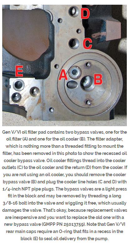
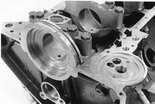
MARK VI BLOCK OIL CONNECTIONS
Ive always found it rather curious, why guys build SBC vs BBC engines,if they are starting from scratch,
keep in mind a properly built BBC engine has better flowing heads and larger displacement, etc.
if either engine makes lets say 1.2 hp per cubic inch your 383 potentially makes 460hp vs 596hpo for a 496 big block
now guys will instantly point out the BBC weights more but if it weights 120lbs more in a car that weights 3100lbs with a SBC and 3220 with a big block, the SBC produces 6.7lbs per hp vs 5.4lbs per hp for the big block

http://scatcrankshafts.com/
0704ch_15_z+chevy_big_blocka.jpg

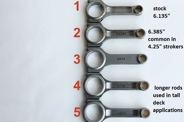
common BB CHEVY piston compression heights are
1.270"
1.395"
1.520"
1.645"
1.765"
remember the blocks deck height, minus the piston pin height minus 1/2 the crank stroke will equal the required connecting rod length
OR
the blocks deck height, minus the connecting rod length, minus 1/2 the crank stroke. will equal the required piston pin height
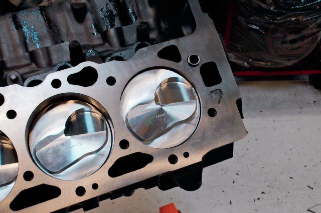
yes its common for a combo to have the piston deck height located .010-.015 above or below the deck of the block so you'll need to select a head gasket thickness that compensates, too allow your engine to get a .038-.044 piston deck to cylinder head QUENCH DISTANCE.

thats the difference between high 11 to low 12 second 1/4 mile times with a SBC vs very low 11 seconds or high 10 seconds with the BBC

bbcgasketma.png


There are gaskets made specifically for this swap. Use other gaskets at you're own risk- these are what you want (from a V/R press release, presumably prior to the Gen 6 engine release):

General Motors 7.4L Head Gasket
Issue:

General Motors (GM) 7.4L (454 CID) engines use two types of engine blocks: the Mark IV and Mark V. The Mark IV is found on 7.4L engines in model years from 1965 to 1990, and the Mark V is found on 7.4L engines in model years from 1991 and newer.

Often, installers will attempt to adapt a Mark IVcylinder head for a Mark V block. This conversion can be made if attention is paid to the coolant circulation. Mark IV and Mark V have different coolant flows and were originally designed for different head gaskets. If the conversion is not performed correctly, the engine will overheat, causing premature engine wear and damage.

Resolution:
Victor Reinz has designed two Nitroseal® head gaskets to specifically allow for this conversion. The installation requires Victor Reinz part number 4918 be installed on the right cylinder bank to maintain proper coolant circulation, and part number 4923 to be installed on the left cylinder bank for the correct coolant flow.

Application:
Victor Reinz part numbers 4918(right bank) and 4923 (left bank) are available for GM 7.4L (454 CID)
engines.
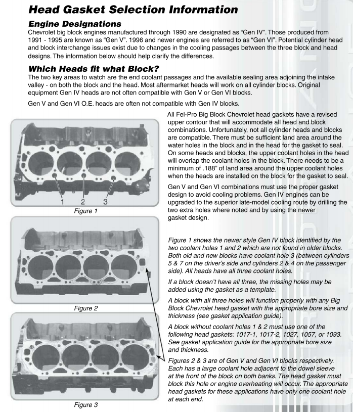
mark iv blocks
mrkiv.jpg

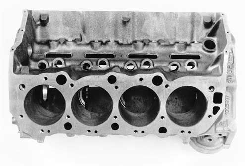
mark v blocks
markv.jpg

(keep in mind that ALL '91 and later Gen.V and Gen.VI big blocks come with 4-bolt main caps. The two-bolt big blocks are no longer in production
MANY BUT NOT ALL aftermarket head designs have been modified to work on both the early MARK IV 1965-90 and later MARK V & VI blocks 1991-later.)

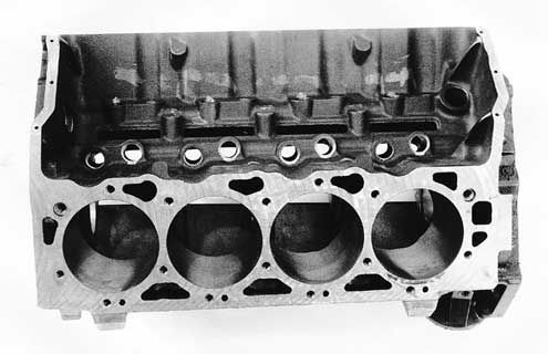
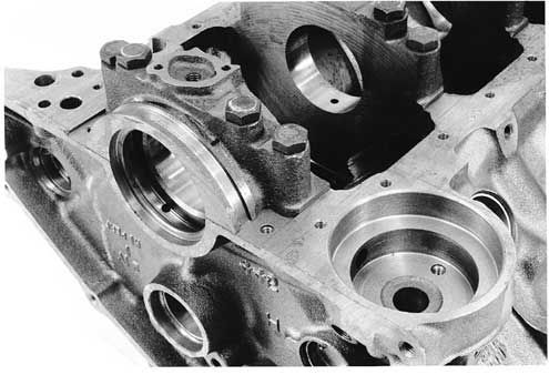
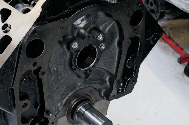
BTW, , on BIG BLOCKS the oil pumps and oil filter adapters are different due to the block oil filter recess and rear seals being different
GEN 4 or MARK IV
bbcmk4.jpg


GEN V and VI
bbcmkv.jpg


Btw heres a tip learned through experience , if your 496 -540 displacement BBC combo includes an engine with at least 10:1 compression and a cam with at least 240 duration at .050 lift, and oval port heads, youll almost always find a single plane intake has some advantages over a dual plane intake.
https://www.holley.com/products/intakes/single_plane_manifolds/parts/7620
7620_2[583x].jpg


SV565.jpg

http://www.race-cars.net/calculators/et_calculator.html

viewtopic.php?f=69&t=3153

viewtopic.php?f=69&t=9930

viewtopic.php?f=69&t=5123

viewtopic.php?f=51&t=976&p=1827&hilit=BIG+BLOCK+SMALL#p1827

viewtopic.php?f=69&t=1432
 
Last edited by a moderator:
Pat_McNeil said:
My new engine for the Chevelle was dyno tested today!!! All I can say is WOW!!! 765hp and 637 ft lbs of tq..Bryce at Dr J's Performance built one awesome pump gas bruiser. It's everything I asked for and more . Here's some info Bryce set me on the engine

Dr J's pump gas 496 BBC

4.310 bore X 4.25 stroke
probe 18cc dome shelf pistons 11.10 to 1 compression
Scatt 4340 crank and H beam rods
Custom Isky solid roller .750 lift intake .720 lift exhaust 270/274 @ .050 108 lca
Jesel Sportsman rockers

AirWolf 305 CNC ported oval port heads(edelbrock castings)
2.300 intake and 1.900 exhaust valves
109cc chambers

Ported Dart 4150 intake with 4500 adapter
Dr J's 1150 4500 carb


http://www.youtube.com/watch?feature=pl ... Zw14Q3CT5s

496 pump gas BBC 765hp!!! Airwolf 305 heads - YouTube[/url]

https://www.billmitchellproducts.com/world-cast-iron-26degree-269cc/
 
Last edited by a moderator:
http://www.superchevy.com/how-to/engine ... -big-bros/


Here at Super Chevy we can’t help but get excited about new products, especially when they are designed for big-blocks. Let’s face it, nothing rocks harder than big-inch engines, and if some displacement is good, then more is even better. Brodix recently contacted us and offered up a set of its new BB-3 Xtra 345 heads designed for high-horsepower Rat applications. What makes these new BB-3 heads so special? The new heads flow over 400 cfm, but though there are other BBC heads with matching flow numbers, these BB-3 Xtra heads offered the amazing flow with intake port volumes measuring just 345 cc. The combination of big flow and minimal port volume make the heads not only powerful, but versatile for a wide variety of applications.

Putting these numbers into perspective is the fact that a set of stock (iron) rectangle-port BBC heads check in with 325-330cc intake ports that flow just 330 cfm. Compared to stock BBC rec-port heads, the new Brodix heads offer a whopping 26 percent increase in flow with an insignificant 4-6 percent increase in port volume.
View Michelin Tires Winter Promotion

before you spend a good deal of money porting and un-shrouding any iron cylinder heads, keep in mind aluminum heads are easily repaired in a skilled and experienced automotive machine shop thats equipped to do those repairs but damaged iron cylinder heads are either much harder to repair or good door stops
http://garage.grumpysperformance.com/index.php?threads/iron-vs-aluminum-heads.389/#post-7266
The sizable flow numbers alone indicate that these heads will support over 830 hp, but we wanted to see how they faired on a more reasonable street/strip Rat. Not everyone builds max-effort race engines, so we decided to build something that represented a hot street engine that saw occasional strip action (or vice-versa). Since big inches equal big power, we decided that the Xtra 345s deserved something larger than your standard-issue 454. Besides, it gave us a chance to visit the local wrecking yard and snatch up a big-block core. There is nothing more satisfying than resurrecting a tired soldier and bringing it back to life, especially when said soldier will be ditching the iron peanut ports for a set of new Brodix aluminum heads. Though our first choice was an original Mark IV, we were unable to locate one and settled on a late-model Gen VI block. The Gen VI offered many desirable qualities, including four-bolt mains and factory hydraulic roller cam, but the late-model 7.4L block lacked the provision for a mechanical fuel pump. It should also be noted that the Gen VI block required a crank designed for the one-piece rear main seal.

The core short-block was stripped of its internals and machined by L&R Automotive to receive a forged rotating assembly consisting of a 4.25-inch stroker crank and 6.385-inch rods from Speedmaster combined with a set of forged pistons from Probe Racing. Each Probe piston featured an 18cc dome to produce a static compression ratio of 10.0:1 when combined with a 119cc combustion chamber. Finishing up the stroker short-block was a ring package from Total Seal and rod and main bearings from Clevite. Though the Gen VI block was designed to accept a hydraulic roller cam, we opted to install a solid roller grind, which required the elimination of both the cam retaining plate and lifter retention assembly. They were replaced with a solid roller cam from Crane Cams that offered 0.714-inch lift, a 262/272-degree duration split, and 106-degree LSA. The tall lifter bores in the Gen VI block required the use of a set of 0.300-tall solid roller lifters from Comp Cams. The cam was retained using a cam button, double-roller timing chain, and two-piece (aluminum) timing cover from Comp Cams.

The short-block was now in a position to accept its crowning glory in the form of the new Brodix BB-3 Xtra aluminum heads. They feature a unique combination of flow and port volume that made them not just extremely powerful but flexible as well. Big-block flow numbers exceeding 400 cfm are impressive enough, but even more so when they come from intake ports measuring just 345 cc. Big flow through small ports is the quintessential measure of efficiency. Big flow can support massive displacement and power numbers (over 830 hp in the case of the 417 cfm), but the 345cc port volumes mean the heads will be right at home on a smaller 454 or (in our case) 496. Heck, we wouldn’t hesitate to run these on a 427 or 396, though the power potential would be wasted on these milder (and smaller bore) applications.

Contributing to the impressive flow numbers was a rolled valve angle (from 26-24 degrees), a 2.30/1.88 valve combination, and an 0.800-lift roller-cam valvespring package.

Though our 496 stroker was purposely kept on the street/strip side of the equation, we made sure to minimize flow limitations to the Brodix heads.

The induction system consisted of a Holley 1050 Ultra Dominator feeding a single-plane intake from Speedmaster. The single-plane intake was chosen for its rpm ability, since we had plenty of head flow and cam timing. The induction system must work with the heads and cam timing to optimize power production in the desired rpm range. A dual-plane would limit power production above 4,000 rpm on this application, so we went with the 4500-series intake from Speedmaster.

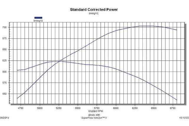
Finishing up the Brodix-headed 496 was a Milodon oiling system, an MSD billet distributor, and set of Crane Gold roller rockers. After a break-in, we were rewarded with peak numbers of 703 hp and 623 lb-ft of torque. There is always more power to be had from any combination with increased compression ratio, wilder cam timing, and (of course) boost, but revel in the fact that this 496 was a perfect little street/strip stroker. We also smile knowing that should we decide to, these heads will support almost anything we decide to put under them.
Brodix Headed Test Engine 2/18

01. What we do to wring every last ounce of horsepower out of our Brodix-headed test engine.
4340 Stroker Crank 3/18

02. The four-bolt Gen VI BBC test mule was sporting 496 inches thanks to a 4340 stroker crank and rods from Speedmaster.
Pistons 4/18

03. Probe Racing supplied a set of 0.070-over pistons for our BBC build. The 18cc domes worked with the 119cc combustion chambers to produce a static compression ratio of 10.0:1—perfect for unleaded premium. The pistons were installed using a Total Seal ring package.
Generation 6 Block 5/18

04. The Gen VI block featured provisions for a cam retaining plate to be used with the factory hydraulic roller cam, but we opted to run a solid roller grind.
Crane Solid Roller Cam 6/18

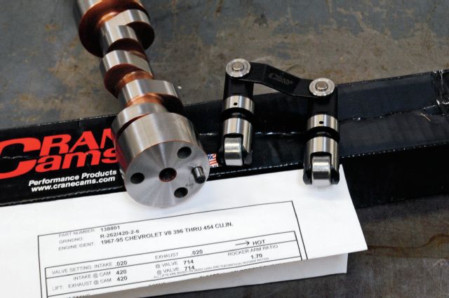
05. The Crane solid roller cam offered 0.714-inch lift, a 262/272-degree duration split, and tight 106-degree LSA. The cam was teamed with a set of 0.300-tall (required for the Gen VI block) solid roller lifters from Comp Cams.
Double Roller Timing Chain 7/18

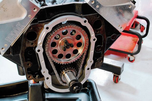
06. A double-roller timing chain was employed that required the use of a cam button and custom timing cover.
Comp Cams 8/18

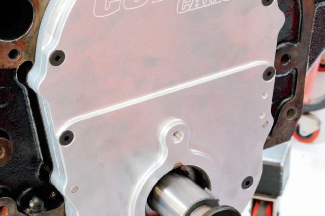
07. Comp Cams stepped up to supply the necessary two-piece, aluminum Gen VI timing cover.
Milodon Hv Oil Pump 9/18

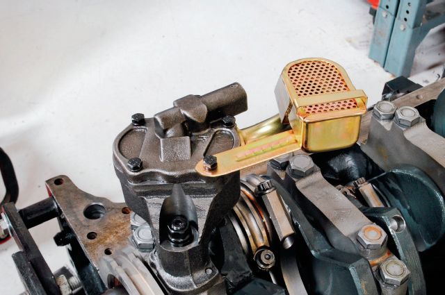
08. Oiling is critical so we installed this Milodon HV oil pump and pickup designed to work specifically with the supplied oil pan. Note the ARP pump stud and Extreme Duty brace on the pickup used to secure it to the pump (never rely on just a press fit).

16. Run on the dyno, the Brodix-headed 496 stroker produced peak numbers of 703 hp at 6,400 rpm and 623 lb-ft of torque at 5,200 rpm. Having massive head flow means you can make big power with milder cam timing and pump-gas compression ratios.

Making over 700 hp with a 496 is easy when you install heads capable of supporting over 800 hp. The Brodix BB-3 Xtra 345 heads combined massive head flow with minimal port volume, making them ideally suited for a wide variety of displacements and configurations. The Brodix heads teamed with the single-plane intake and Crane roller cam to produce 703 hp and 623 lb-ft of torque. The great thing about this combination is that it is now ready for nitrous, boost, or even wilder cam
w496a.jpg

w496b.jpg

w496c.jpg

w496d.jpg

w496e.jpg

w496f.jpg

w496g.jpg

w496h.jpg

w496i.jpg

w496j.jpg
 
Last edited by a moderator:
Find anything Grumpy that's conclusive what a production 427 Tall Deck BBC Can take before blockk failure ?
Thinking most of the high HP 496 Builds in magazines use Dart Iron Tall Decks blocks to start.
 
I would not be the least bit hesitant to build a 650hp-750hp engine combo with that tall deck block as long as you had it sonic tested for cracks/flaws, without finding any and kept the bore wall thickness at least .180, and did not exceed .060 over bore diam. but I also know that those numbers are frequently exceeded ,and while I see mixed results adding power or thinner metal is bound to result in higher failure rates eventually,the fact that I see the engines holding up well at that 650hp-750hp level, that does not indicate in my mind that the stock blocks a great choice for building something like a 1200hp turbo engine build.(it might function flawlessly but if I'm putting that much time and cash into an engine, I expected to exceed 1000 hp I'd be rather inclined, to buy a dart block as Id be LESS worried abought the much thicker casting in the bore walls and main webs failing or main caps chattering or cracking under the stress)
for something like that in my mind theres zero question I'd vastly prefer a DART block as the casting is thicker and the web design on the main caps is certainly thicker and the alloy used is higher strength,) but it certainly indicates the stock tall deck ,four bolt main cap,big block , engine block casting is significantly more rigid that a similar SBC block


RELATED
viewtopic.php?f=51&t=125

viewtopic.php?f=51&t=710

viewtopic.php?f=51&t=976

viewtopic.php?f=51&t=188

viewtopic.php?f=51&t=6162

viewtopic.php?f=51&t=3363
 
http://www.powerblocktv.com/episode/HP2 ... MZvJS7O2PI

yeah! the constant ADDS in the video are a P.I.T.A. but theres still enough good info to be worth watching.
yeah! keep in mind they seem to be rather intent on selling parts and yeah I'm personally thinking the results might be a bit better with some changes in parts used.
but they do post a few tips and over all I think its a decent build and theres some helpful advice.
 
grumpyvette said:
http://www.powerblocktv.com/episode/HP2013-13/double-power-adder-big-block#.VMZvJS7O2PI

yeah! the constant ADDS in the video are a P.I.T.A. but theres still enough good info to be worth watching.
yeah! keep in mind they seem to be rather intent on selling parts and yeah I'm personally thinking the results might be a bit better with some changes in parts used.
but they do post a few tips and over all I think its a decent build and theres some helpful advice.

every time those guys pulled out a new part i was like oh shit there goes another two weeks pay, i think they showed off about 6 months of pay in that video!
 
philly said:
grumpyvette said:
http://www.powerblocktv.com/episode/HP2013-13/double-power-adder-big-block#.VMZvJS7O2PI

yeah! the constant ADDS in the video are a P.I.T.A. but theres still enough good info to be worth watching.
yeah! keep in mind they seem to be rather intent on selling parts and yeah I'm personally thinking the results might be a bit better with some changes in parts used.
but they do post a few tips and over all I think its a decent build and theres some helpful advice.

every time those guys pulled out a new part i was like oh shit there goes another two weeks pay, i think they showed off about 6 months of pay in that video!


yeah it was painfully obvious that was 75% parts promotion and sales device and only 25% engine building instructional tips and info, there that most guys can use,, yet it was still useful as an instructional tool.

http://www.lunatipower.com/Tech/Pistons/CompressionHeight.aspx

http://www.doverusa.com/compression-height-calculator.php

https://www.uempistons.com/index.ph...n_comp&zenid=a1250756cef845700c8510712d829d4f

Piston compression height is the distance between the centerline of the pin to the flat part of the top of the piston. It's important to know this number when ordering pistons--especially custom ones--so that the piston falls in the right place in relation to the deck surface of the block (where the cylinder head bolts on). To figure out the best compression height, you need to know your block's deck height, the length of your connecting rods, and your crank stroke.

Block deck height is the distance from the centerline of the main journals to the block deck surface. For example, the small-block Chevys we tested last month were delivered at 9.020 inches, though this is commonly machined to 9.00--and giving or taking that 0.020 really makes a difference.

So assume you have a block with a 9.00-inch deck height, 6.000-inch connecting rods, and a stroke of 3.75 inches. First, divide the stroke by two and add that to the rod length: 3.75 / 2 = 1.875, and 1.875 + 6.00 = 7.875. Next, subtract that answer from the deck height: 9.00 – 7.875 = 1.125. So the answer is that the piston compression height should be 1.125 inches.

That will put the top of the piston exactly at the top of the engine block, which is usually best for quench and performance. If you want the piston to be 0.010 above or below the deck, simply add or subtract that amount from the compression height. Easy.
 
Last edited by a moderator:
i do like how they show short clips of basically photo instructions on what the steps look like for putting some of those parts on. its never as easy as they make it sound, but you get the jist of it. also on all that website videos youll always see them talking about lubrication, assembly lube (and theres probably over a minute of combined footage of them brushing that shit on EVERYTHING) and also break in lube, some videos go into the break in process for different cams, hot lash setting, things like that are things that are actually instruction and not just the pornography of the awesome shiny parts and wicked dyno pulls... i like those guys videos.
 
anytime you find a video or posted info, post a link and comments
like this link
http://www.hotrod.com/how-to/engine/suc ... ock-build/
gve1.jpg


gve2.jpg

gve3.jpg

gve4.jpg

gve5.jpg

gve6.jpg

Directions for crankshaft grinding and polishing
Crankshaft journal surfaces should be ground and polished to a surface finish of 15 micro inches roughness average Ra or better. Journals on highly loaded crankshafts such as diesel engines or high performance racing engines require a finish of 10 micro inches Ra or better.

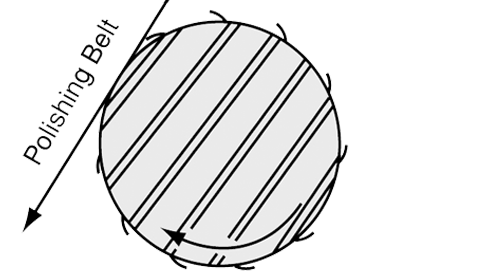
The above is a simple straight forward specification which can be measured with special equipment. However, there is more to generating a ground and polished surface than just meeting the roughness specification. To prevent rapid, premature wear of the crankshaft bearings and to aid in the formation of an oil film, journal surfaces must be ground opposite to engine rotation and polished in the direction of rotation. This recommendation and examination of the following illustrations will help make the recommendation more clear.

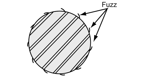
Metal removal tends to raise burrs. This is true of nearly all metal removal processes. Different processes create different types of burrs. Grinding and polishing produces burrs that are so small that we can't see or feel them but they are there and can damage bearings if the shaft surface is not generated in the proper way. Rather than "burrs", let's call what results from grinding and polishing "microscopic fuzz." This better describes what is left by these processes. This microscopic fuzz has a grain or lay to it like the hair on a dog's back. Figure 1 is an illustration depicting the lay of this fuzz on a journal. (Note: All figures are viewed from nose end of crankshaft.)

crankfigure1.gif

The direction in which a grinding wheel or polishing belt passes over the journal surface will determine the lay of the micro fuzz.

In order to remove this fuzz from the surface, each successive operation should pass over the journal in the opposite direction so that the fuzz will be bent over backward and removed. Polishing in the same direction as grinding would not effectively remove this fuzz because it would merely lay down and then spring up again. Polishing must, therefore, be done opposite to grinding in order to improve the surface.

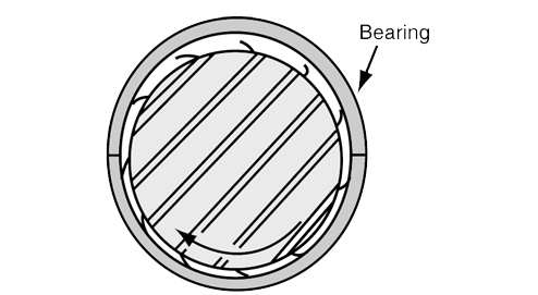
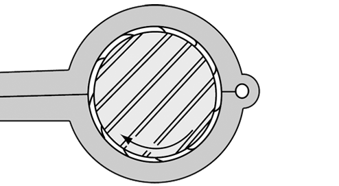
In order to arrive at how a shaft should be ground and polished, we must first determine the desired end result and then work backwards to establish how to achieve it. Figure 2 depicts a shaft turning in a bearing viewed from the front of a normal clockwise rotating engine. The desired condition is a journal with any fuzz left by the polishing operation oriented so it will lay down as the shaft passes over the bearing (Figure 2).

crankfigure2.gif

The analogy to the shaft passing over the bearing is like petting a dog from head to tail. A shaft polished in the opposite direction produces abrasion to the bearing which would be like petting a dog from tail to head. To generate a surface lay like that shown in Figure 2, the polishing belt must pass over the shaft surface as shown in Figure 3.

crankfigure3.gif

The direction of shaft rotation during polishing is not critical if a motorized belt type polisher is used because the belt runs much faster than the shaft. If a nutcracker-type polisher is used, then proper shaft rotation must be observed (Figure 4). Stock removal during polishing must not exceed .0002" on the diameter.

crankfigure4.gif

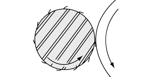
Having determined the desired surface lay from polishing, we must next establish the proper direction for grinding to produce a surface lay opposite to that resulting from polishing. Figure 5 shows the grinding wheel and shaft directions of rotation and surface lay for grinding when viewed from the front or nose end of the crankshaft. This orientation will be achieved by chucking the flywheel flange at the left side of the grinder (in the headstock). Achieving the best possible surface finish during grinding will reduce the stock removal necessary during polishing.

crankfigure5.gif

The surface lay generated by grinding would cause abrasion to the bearing surfaces if left unpolished. By polishing in the direction shown in either Figure 3 or 4, the surface lay is reversed by the polishing operation removing fuzz created by grinding and leaving a surface lay which will not abrade the bearing surface.

Nodular cast iron shafts are particularly difficult to grind and polish because of the structure of the iron. Nodular iron gets its name from the nodular form of the graphite in this material. Grinding opens graphite nodules located at the surface of the journal leaving ragged edges which will damage a bearing. Polishing in the proper direction will remove the ragged edges from these open nodules.

All of the above is based on normal clockwise engine rotation when viewed from the front of the engine. For crankshafts which rotate counterclockwise, such as some marine engines, the crankshaft should be chucked at its opposite end during grinding and polishing. This is the same as viewing the crank from the flanged end rather than the nose end in the accompanying figures.

Unlike many engine bearings available today, Clevite engine bearings utilize a superior Clevite TriMetal™ material design. Stamped "Clevite®," this design incorporates the strength of a copper-lead alloy layer on a steel back and finally, a precision electroplated white metal "babbitt" third layer. TriMetal™ is an ideal bearing design producing good to excellent characteristics when judged for conformability, embedability, slipperiness and fatigue resistance.

We constantly monitor the function and operation of our full line of bearings, staying in touch with any changes or developments that new engines may require. And that translates into bearings that are better for your engine. If you're looking for the engine bearings that set the standards, specify Clevite®. Because you won't settle for second best.


gve7.jpg
 
Last edited by a moderator:
VORTECPRO said:
I built a 10.7 compression 496 a few weeks back for one of our board members,
although I'am trying to focus more on aftermarket builds now there are still a few more of these production builds to do.
I thought I'd share the results with the forum. This was a 959 two bolt block, with a Scat 4340 crank, 6.385 I beam rods with modified Mahle pistons, the cam was a Comp billet roller with Morel lifters, valves were Manley with tool room Isky springs, heads were 781 oval port heads with a Victor Jr intake, Oil pan was a Milodon, carb was a 1000 CFM 4150, oil was LAT, gas was VP C-12.

attachment.php
 
What I know now is to take a 427 Tall Deck Block production block and build a 496 you end up with cylinder walls of .140-.180 thick only typical .
Must Hard Block it or MOROSO BLOCK FILL IT.

455 Pontiac production blocks have .300"-.400" thick walls after .030" overbore.
I know because I had them Sonic tested and was right there while it was done.

Be more inclined to run 427 cubes as is with a True Race Cam of 85-100 degrees overlap.
Use factory iron heads.
Or 454 cubes all iron .
Production parts used just as A Pontiac V8.
 
Proud to be a Pontiac Guy Grumpy.
I can use 90% all given to me in Production 455's.

SBC You throw all away immediately .
Pick up the Summit Catalog. Spend $10k and still slow.

BBC OK.
 
http://www.airflowresearch.com/chevy-high-performance-nov-2008-355cc-bbc.php
rformance
Dyno
Articles
FAQ
Installation Instructions
Spring Spec
Catalog
Contact
Products
BBC LSX SBC SBC LT SBF Manifolds Parts & Accessories Valve Covers
More Links
Dealer Listings AFR Repair Centers 2009 AFR Price List AFR Testimonials Recommendation Form Shipping and Returns Privacy Notice Contact Us
Westech Performance 496 Chevy Big Block Build - A Monster Is Born
Westech Performance Builds A 496CI Brute
By Sean Haggai
Super Chevy, Nov 1, 2008
Click image below to view image gallery


We would like to think that all engines are created equally, only that's never the case, which is why it's so crucial to blend the right components together from the get-go. The old adage "There is no replacement for displacement" rings true-especially once you've taken into account the fact that we've got 496 ci of paint-can-sized bores and steamboat stroke. Nowadays, the price gap between a small-block and a big-block is minimal but the power output can be substantially greater when you've got more cubes on your side. So if you are going to go for it, what better way than with some major guts? Everyone gets their kicks at the sight of a chest-thumping big-block cradled on the dyno. Like the Buddhist statue you spot in people's houses, you can't help but want to rub its belly. To put it simply, they're just cool.

Hosting this gig was Steve Brul. If the name sounds familiar, that's because he's been the front man and our personal go-to guy for years, running the Westech Performance facility. Brul is no slouch, especially when holding the Westech Performance name in the balance. When it came time to bring a combination of components together to make serious muscle, Brul had a reputation to uphold-and uphold it he did. He accomplished his goal and then some and came out a hero. How did he fare? To begin with, he knew big cubes were going to reign supreme in the land of longevity and when the time comes for serious squeeze, the 12 points of compression would always help to coax out the power. As Brul puts it, "Why would you want to build anything that won't last?" So beginning with a bored 0.060-over Gen VI block, Brul began to piece his latest combination together. He also called on some serious players in the aftermarket world of performance to get the job finished. All said and done, Brul managed a slick 780 hp and 658 lb-ft.

We went behind the scenes, following Brul to see what went into creating this monster and listed all of the components used. While there are so many ways of piecing a motor together, we'd venture to say that in this case, Brul nailed the combo without a hitch, and if nothing else, it's already a proven package. If you want something similar for your street machine, then follow along as we unveil one man's recipe

496we2.png
496we1.png


http://www.lunatipower.com/Tech/Pistons/CompressionHeight.aspx

http://www.doverusa.com/compression-height-calculator.php

https://www.uempistons.com/index.ph...n_comp&zenid=a1250756cef845700c8510712d829d4f

Piston compression height is the distance between the centerline of the pin to the flat part of the top of the piston. It's important to know this number when ordering pistons--especially custom ones--so that the piston falls in the right place in relation to the deck surface of the block (where the cylinder head bolts on). To figure out the best compression height, you need to know your block's deck height, the length of your connecting rods, and your crank stroke.

Block deck height is the distance from the centerline of the main journals to the block deck surface. For example, the small-block Chevys we tested last month were delivered at 9.020 inches, though this is commonly machined to 9.00--and giving or taking that 0.020 really makes a difference.

So assume you have a block with a 9.00-inch deck height, 6.000-inch connecting rods, and a stroke of 3.75 inches. First, divide the stroke by two and add that to the rod length: 3.75 / 2 = 1.875, and 1.875 + 6.00 = 7.875. Next, subtract that answer from the deck height: 9.00 – 7.875 = 1.125. So the answer is that the piston compression height should be 1.125 inches.

That will put the top of the piston exactly at the top of the engine block, which is usually best for quench and performance. If you want the piston to be 0.010 above or below the deck, simply add or subtract that amount from the compression height. Easy.
 
Last edited by a moderator:
heres a link directly to the cam they alledgedly used in that motor.... the not too detailed article says 12 points of compression but no mention as to what was done to the heads, intake, and pistons to "coax" the power out. at that output you are literally talking about porting pistons and blueprinting moves on blocks that never get published... i bet there was a crankcase vacuum pump involved there too....

http://www.compcams.com/Company/CC/cam-specs/Details.aspx?csid=515&sb=2
 
CPMotorworks said:
Not to fuel any oval/rectangle debates...but thought some of you would find this interesting. This is similar to some of the numbers builds I've done for some mid year Corvettes minus the head porting and bigger carb.
This one is destined for a '66 Chevelle with a TKO T56 6 speed and 19" wheels, street car/pro touring style deal. Will get used for short and long road trips and road racing at the local tracks.
Working with some of the parts he already had from the prior setup he wasn't happy with-
RPM Air Gap- to fit under the stock 66 hood without issues
188 Iron Heads
289 4 bolt block

So typical block work, line hone, deck, bore, hone with plate, hone lifter bores, etc.
Molnar 4340 forged crank and Rods, RaceTec Pistons and rings, Powerbond SFI dampner and Hays 26lb flywheel
Heads received Ferrea 2.19/1.88 valves, PAC Springs, Ultra Pro Rockers, Manton pushrods. Decent valve job and 10 minutes of bowl porting, 45 minutes in chamber work.
Cam is Comp hydraulic lobes, 24x/24x, 110 lsa, .640 lift
QFT 4150, 3/4" open spacer, MSD 85551 with 37°, 92 octane with 10% ethanol from the BP station.
2" x 3.5" headers
900 rpm idle is 12" vac, so very mild.

Had it on the dyno last Friday and it worked pretty good. Owners happy, dyno owner was impressed, and my Dad came along for the day to see how the whole process goes and to see what it's like. I can't wait to see the owners face when he realizes it will smoke the tires at will in 3rd gear :)

Anyway- everyone likes photos-

11113944_856318017772905_3465178697534052488_n.jpg


10408567_874275375977169_294247964854285066_n.jpg


11407292_875588452512528_4594615675411572688_n.jpg


11392876_875588595845847_5714581098769650343_n.jpg


11392784_874276632643710_7192726797197239873_n.jpg


11377239_874280242643349_695608640596118799_n.jpg


10501935_874280245976682_3099919701902572086_n.jpg

680 ft lbs at 4500 rpm and 685 hp at 6100 rpm are decent numbers for that chevy cylinder head, and a fairly mild hydraulic cam
11391300_978049665538670_5448578127276251816_n.jpg


Last edited:
We are getting down to the Nitty Grit Grumpy.
Real World Poor Man's BBC Builds for Phil and Me.
Bam Bam screwed up a lot for Mechanics like us.
Good paying sidejobs hard to find.
Most want to pay you $5 to $20 bucks for a Full days work fixing thier Junk cars and trucks.

Also not a chance in Hell I am selling my Pontiac 455 parts & Olds 425 to fund a 496 BBC Build.
Value of Poncho in $$$$ much higher than Chevy right now.
 
Back
Top