If you've ever hit a speed bump in the road thats meant to slow traffic, at several different speeds, you know theres a very noticeable relationship between the speed somethings moving and time it takes for inertia and mass of a moving object to change, direction when force is applied thru the use of a ramp changing its path of movement, and the resulting increase in shock to the components as the rate of that change over a shorter time is applied.
a speed bump is similar to a cams lobe acceleration ramp, in that it lifts the lifter/valve against spring resistance similar to your cars wheel hitting the speed bump.
a cams lobe design can rather gradually or rather suddenly impart a change in direction to the lifter in its bore and effect the speed at which the valve lifts off its seat or returns to a closed position, but that ramp design has a huge effect on the stress the valve train is subjected to as the speed of engine rotation is increased.
just like your car hitting the speed bump in the road, theres a big difference at 7 miles per hour vs 70 miles per hour, and a cam lobe that pops the valves open at idle speed of 700rpm,imparts far less stress than the same lobe spinning at 7000rpm.
naturally every choice is a compromise, lower lifts and smoother low acceleration rates make for long life and lower stress but restrict the potential area open under the valve per degree of rotation, which restricts potential breathing of the engine.
rapid ramp acceleration rates tend to increase potential hp but impart higher stress
Isky claims that the Comp XE cams violate the 47.5% rule. The 47.5% rule applies to flat tappet cams for SBCs with 1.5 rockers but the concept is still the same for other configurations where the designs are "on the edge" or "over the edge" for lobe intensity. For 1.5 ratio SBCs, the duration at .50 must exceed 47.5% of the total valve lift or your asking valve train problems. For example, take a Comp Cams Magnum 280H, with 230 duration and, 480 lift...230/.480 = 47.9% which exceeds 47.5% therefore would not pose a threat to components. We do not regularly hear about the older, safer HE and Magnum designs rounding off lobes anywhere near as often as the XE cam designs. Unfortunately, some of the Comp Cams XE dual pattern lobes break this 47.5% rule on the intake side so they are likely to be problematic. The design has "steeper" ramps that are too quick for durability and reliability according to other cam manufacturers. They will wipe lobes in a heart beat especially if you have not followed the proper break-in procedure. Other designs are more forgiving during break-in and less likely to fail.
one factor I will mention is that each manufacturer tends to look at durability, ramp speeds and max lifter acceleration very differently, one reason I tend to prefer CRANE & CROWER is that they both company's in general realize the engine must finish the race to win and a busted valve train is a HUGE problem,they both realize, and design valve train components and cam lobes with DURABILITY and reliable valve control as top priority,s that are far more important than squeezing every possible potential HP from a cam lobe design at the expense of long term durability
BTW if your running a flat tappet cam INSIST ON A P55 core, to have it ground on as they are far more durable than the cheaper cores
keep in mind in most cases higher valve spring pressures don,t tend to make the engine significantly harder to spin because theres an equal number of valves closing at the same time there are valves opening ,thus much of the increased force or load is off set, but the stress on the lifters and cam lobes, and lifter contact points on the lobes IS increased, so a billet cam core is a nearly mandatory choice at above about 400 ft lbs of valve spring pressure for long term durability and with the faster acceleration rates on most roller cam lobe designs the higher pressures become mandatory to maintain high rpm valve train stability, if you loft a roller lifter valve train,at high rpms, under valve float conditions it frequently and rapidly leads to valve train failures, so verify the required valve springs and clearances with the cam and cylinder head manufacturers before installation
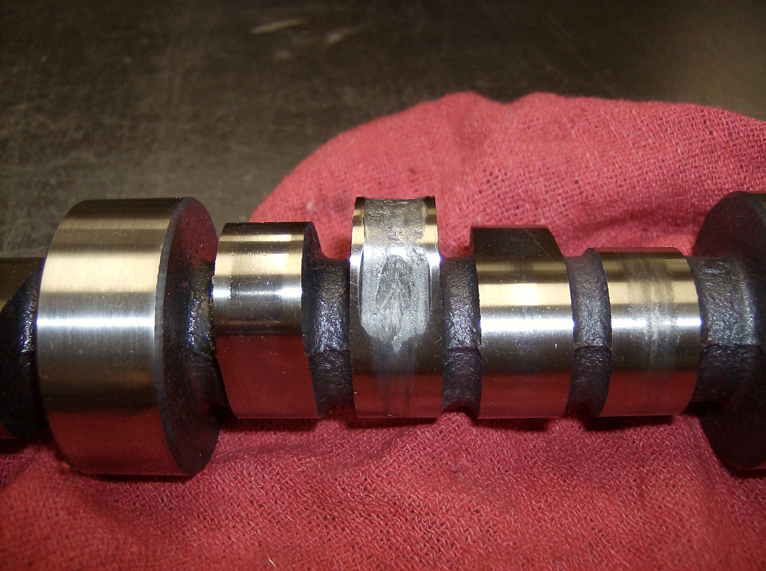
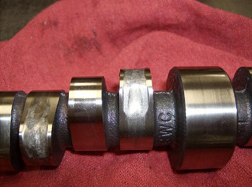
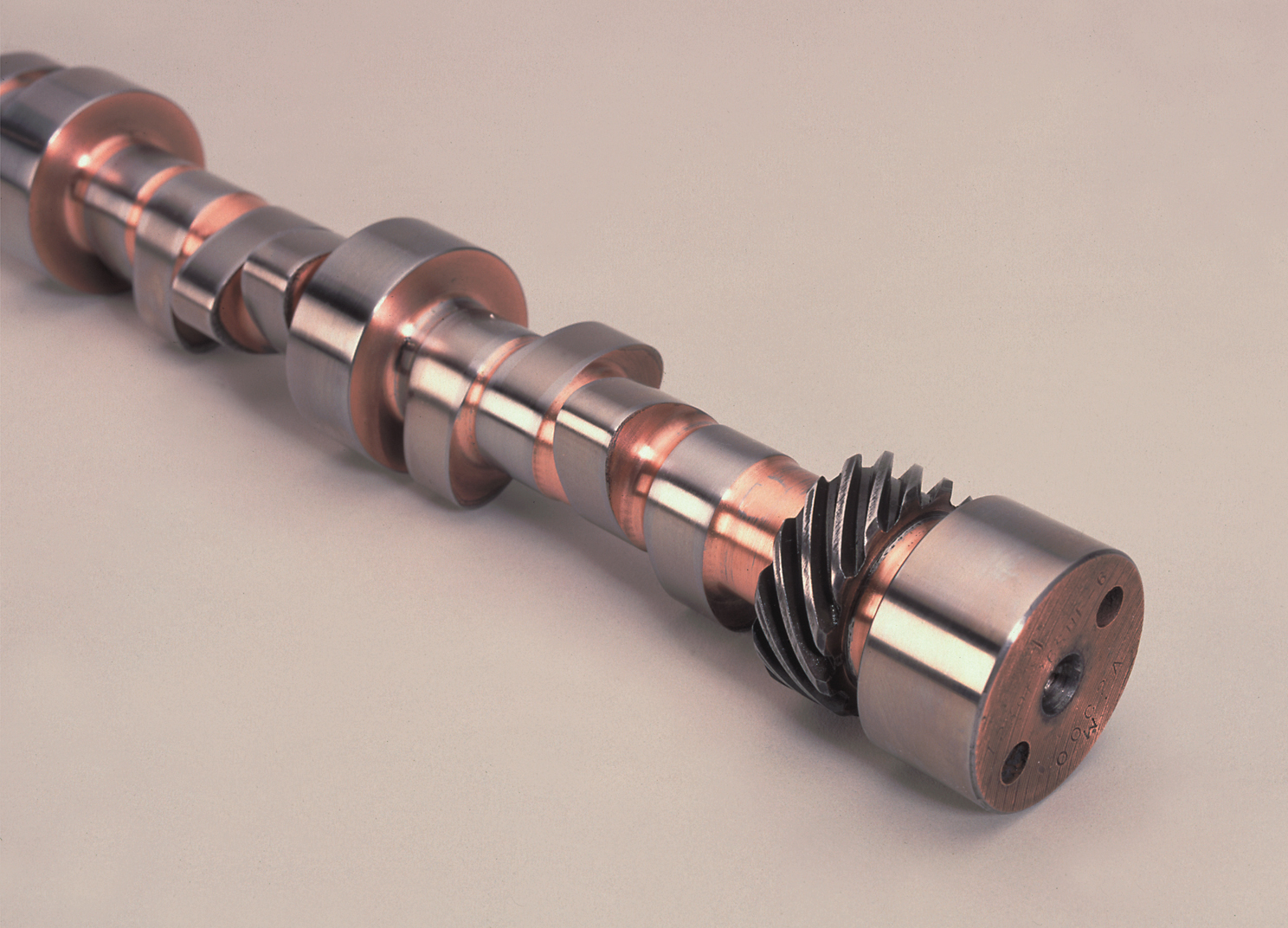
these are both cast core cams (look between the lobes) the dark surface is a flat tappet cam lobe coating, the polished is a roller cam

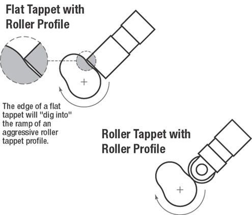
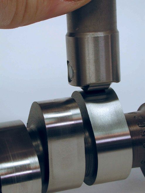
roller lifters can be run on much more aggressive ramp rates, because the edge of a flat tappet lifter will dig into the lobe ramp at a far lower angle than a roller wheel will jam at as either is,lifted on a steep cam lobe as its rotated under a lifter, that trapped in a lifter bore thus the roller cams wheel design allows the valves to be forced open at faster rates and held open longer, increasing air flow rates thru the intake and exhaust ports
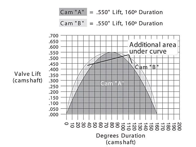
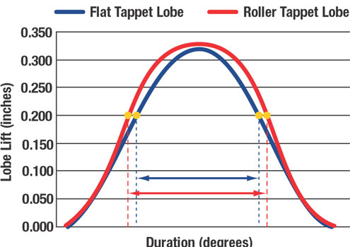
look at this diagram, you'll see with a bit of time examining it that even a cam with the same duration and lift can have a very different ramp acceleration rate, and that would have a big effect on both the total time the valves off its seat (which effects potential power produced)and the stress imparted to the valve train.(which effects the engines stress levels and potential longevity) reducing speed of rotation, spring load rates or the mass(WEIGHT) of the components tends to reduce the stress induced thru rapid changes in direction, of the valve train
ok heres the cliff note version
a roller cam and matched valve train generally costs $700-$1200 MORE than a flat tappet valve train, and cam, and PROVIDED you select the valve train, heads, and intake to match the flow and rpm potential,, and having matched those components correctly, the extra cost, will allow you to pop the valves open and hold them open longer, potentially increasing the air flow into the cylinders, given equal duration and lift on the cams, selected for either application.
theres nothing wrong with a flat tappet solid lifter in most mild-to mid power performance applications but a roller cam has advantages in some cases where you want to maximize the port flow rates and the roller cam usually requires better springs with higher load rates, because the roller lifters weight more and are a bit harder to control (force to remain in constant direct contact with the cam lobes) at higher rpms
you might also keep in mind that you reduce friction,with a roller valve train,reduce heat of the oil, slightly and have a lower tendency to wipe cam lobes, during the normal break-in procedure that's not necessary with a roller cam like it is with the flat tappet cams lifters
READ
http://www.cartechbooks.com/cartech/con ... s/5952.pdf
viewtopic.php?f=52&t=82
http://www.idavette.net/hib/camcon.htm
http://www.summitracing.com/parts/BRO-BR1230/?rtype=10
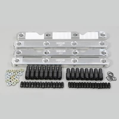
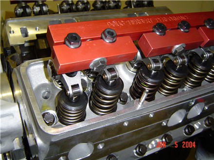
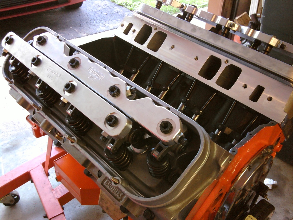
STUD GIRDLES ADD A GREAT DEAL OF RIGIDITY TO THE VALVE TRAIN
high spring loads don,t play well with roller cams over long term use, heres a very clear example of why you should only use Billet cam cores with roller cams having over about 320 lbs of spring pressure and why you MUST verify valve train geometry and clearances.
viewtopic.php?f=52&t=324
http://powermechanics.com/define.html

RELATED BITS OF INFO, yeah theres a great deal of info in the links youll want to read thru
http://www.tildentechnologies.com/Techn ... esign.html
http://www.thirdgen.org/sbc-camshafts-primer
http://www.ovaltracking.com/tech/2006/i ... ive-3.html
http://compcams.com/information/Products/Camshafts/
http://www.motionsoftware.com/downloads ... kStart.pdf
http://www.chevyhiperformance.com/techa ... index.html
http://www.chevyhiperformance.com/tech/ ... index.html
http://www.circletrack.com/enginetech/c ... index.html
http://clubs.hemmings.com/clubsites/mtf ... _stock.htm
http://racingarticles.com/article_racing-69.html
http://www.cranecams.com/?show=camQuestions
http://www.team-integra.net/sections/ar ... ticleID=51
http://www.epi-eng.com/piston_engine_te ... basics.htm
http://www.amotion.com/tech/camtalk.html
http://www.cvsr.net/php/techarticles/areaundercurve.php
http://performancetrends.com/cam_test_stand.htm
http://www.onedirt.com/forum/guide-dirt ... s-883.html
http://scholar.lib.vt.edu/theses/availa ... cobar1.pdf
http://www.superchevy.com/technical/eng ... index.html
a speed bump is similar to a cams lobe acceleration ramp, in that it lifts the lifter/valve against spring resistance similar to your cars wheel hitting the speed bump.
a cams lobe design can rather gradually or rather suddenly impart a change in direction to the lifter in its bore and effect the speed at which the valve lifts off its seat or returns to a closed position, but that ramp design has a huge effect on the stress the valve train is subjected to as the speed of engine rotation is increased.
just like your car hitting the speed bump in the road, theres a big difference at 7 miles per hour vs 70 miles per hour, and a cam lobe that pops the valves open at idle speed of 700rpm,imparts far less stress than the same lobe spinning at 7000rpm.
naturally every choice is a compromise, lower lifts and smoother low acceleration rates make for long life and lower stress but restrict the potential area open under the valve per degree of rotation, which restricts potential breathing of the engine.
rapid ramp acceleration rates tend to increase potential hp but impart higher stress
Isky claims that the Comp XE cams violate the 47.5% rule. The 47.5% rule applies to flat tappet cams for SBCs with 1.5 rockers but the concept is still the same for other configurations where the designs are "on the edge" or "over the edge" for lobe intensity. For 1.5 ratio SBCs, the duration at .50 must exceed 47.5% of the total valve lift or your asking valve train problems. For example, take a Comp Cams Magnum 280H, with 230 duration and, 480 lift...230/.480 = 47.9% which exceeds 47.5% therefore would not pose a threat to components. We do not regularly hear about the older, safer HE and Magnum designs rounding off lobes anywhere near as often as the XE cam designs. Unfortunately, some of the Comp Cams XE dual pattern lobes break this 47.5% rule on the intake side so they are likely to be problematic. The design has "steeper" ramps that are too quick for durability and reliability according to other cam manufacturers. They will wipe lobes in a heart beat especially if you have not followed the proper break-in procedure. Other designs are more forgiving during break-in and less likely to fail.
one factor I will mention is that each manufacturer tends to look at durability, ramp speeds and max lifter acceleration very differently, one reason I tend to prefer CRANE & CROWER is that they both company's in general realize the engine must finish the race to win and a busted valve train is a HUGE problem,they both realize, and design valve train components and cam lobes with DURABILITY and reliable valve control as top priority,s that are far more important than squeezing every possible potential HP from a cam lobe design at the expense of long term durability
BTW if your running a flat tappet cam INSIST ON A P55 core, to have it ground on as they are far more durable than the cheaper cores
keep in mind in most cases higher valve spring pressures don,t tend to make the engine significantly harder to spin because theres an equal number of valves closing at the same time there are valves opening ,thus much of the increased force or load is off set, but the stress on the lifters and cam lobes, and lifter contact points on the lobes IS increased, so a billet cam core is a nearly mandatory choice at above about 400 ft lbs of valve spring pressure for long term durability and with the faster acceleration rates on most roller cam lobe designs the higher pressures become mandatory to maintain high rpm valve train stability, if you loft a roller lifter valve train,at high rpms, under valve float conditions it frequently and rapidly leads to valve train failures, so verify the required valve springs and clearances with the cam and cylinder head manufacturers before installation
these are both cast core cams (look between the lobes) the dark surface is a flat tappet cam lobe coating, the polished is a roller cam
roller lifters can be run on much more aggressive ramp rates, because the edge of a flat tappet lifter will dig into the lobe ramp at a far lower angle than a roller wheel will jam at as either is,lifted on a steep cam lobe as its rotated under a lifter, that trapped in a lifter bore thus the roller cams wheel design allows the valves to be forced open at faster rates and held open longer, increasing air flow rates thru the intake and exhaust ports
look at this diagram, you'll see with a bit of time examining it that even a cam with the same duration and lift can have a very different ramp acceleration rate, and that would have a big effect on both the total time the valves off its seat (which effects potential power produced)and the stress imparted to the valve train.(which effects the engines stress levels and potential longevity) reducing speed of rotation, spring load rates or the mass(WEIGHT) of the components tends to reduce the stress induced thru rapid changes in direction, of the valve train
ok heres the cliff note version
a roller cam and matched valve train generally costs $700-$1200 MORE than a flat tappet valve train, and cam, and PROVIDED you select the valve train, heads, and intake to match the flow and rpm potential,, and having matched those components correctly, the extra cost, will allow you to pop the valves open and hold them open longer, potentially increasing the air flow into the cylinders, given equal duration and lift on the cams, selected for either application.
theres nothing wrong with a flat tappet solid lifter in most mild-to mid power performance applications but a roller cam has advantages in some cases where you want to maximize the port flow rates and the roller cam usually requires better springs with higher load rates, because the roller lifters weight more and are a bit harder to control (force to remain in constant direct contact with the cam lobes) at higher rpms
you might also keep in mind that you reduce friction,with a roller valve train,reduce heat of the oil, slightly and have a lower tendency to wipe cam lobes, during the normal break-in procedure that's not necessary with a roller cam like it is with the flat tappet cams lifters
READ
http://www.cartechbooks.com/cartech/con ... s/5952.pdf
viewtopic.php?f=52&t=82
http://www.idavette.net/hib/camcon.htm
http://www.summitracing.com/parts/BRO-BR1230/?rtype=10
STUD GIRDLES ADD A GREAT DEAL OF RIGIDITY TO THE VALVE TRAIN
high spring loads don,t play well with roller cams over long term use, heres a very clear example of why you should only use Billet cam cores with roller cams having over about 320 lbs of spring pressure and why you MUST verify valve train geometry and clearances.
viewtopic.php?f=52&t=324
http://powermechanics.com/define.html
RELATED BITS OF INFO, yeah theres a great deal of info in the links youll want to read thru
http://www.tildentechnologies.com/Techn ... esign.html
http://www.thirdgen.org/sbc-camshafts-primer
http://www.ovaltracking.com/tech/2006/i ... ive-3.html
http://compcams.com/information/Products/Camshafts/
http://www.motionsoftware.com/downloads ... kStart.pdf
http://www.chevyhiperformance.com/techa ... index.html
http://www.chevyhiperformance.com/tech/ ... index.html
http://www.circletrack.com/enginetech/c ... index.html
http://clubs.hemmings.com/clubsites/mtf ... _stock.htm
http://racingarticles.com/article_racing-69.html
http://www.cranecams.com/?show=camQuestions
http://www.team-integra.net/sections/ar ... ticleID=51
http://www.epi-eng.com/piston_engine_te ... basics.htm
http://www.amotion.com/tech/camtalk.html
http://www.cvsr.net/php/techarticles/areaundercurve.php
http://performancetrends.com/cam_test_stand.htm
http://www.onedirt.com/forum/guide-dirt ... s-883.html
http://scholar.lib.vt.edu/theses/availa ... cobar1.pdf
http://www.superchevy.com/technical/eng ... index.html