cam wear,articles you need to read

grumpyvette

Administrator
Staff member
before, you start reading through the thread and links below,
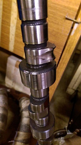
Ill point out that I've done the forensics on quite a few failed cams over the years,
that guys have brought to my shop and Id say about


60%
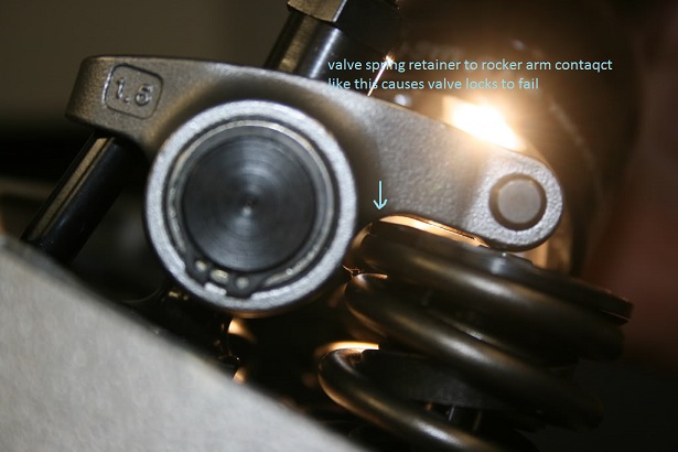
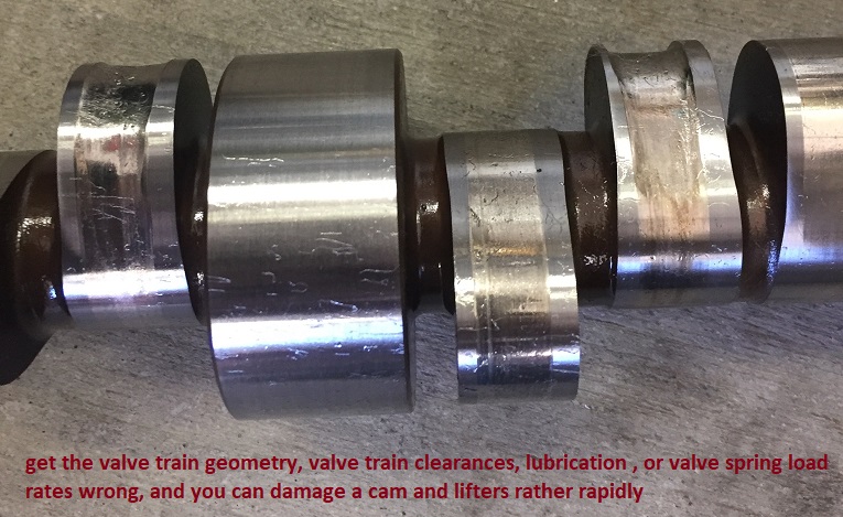
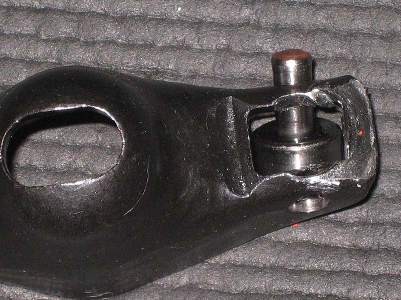
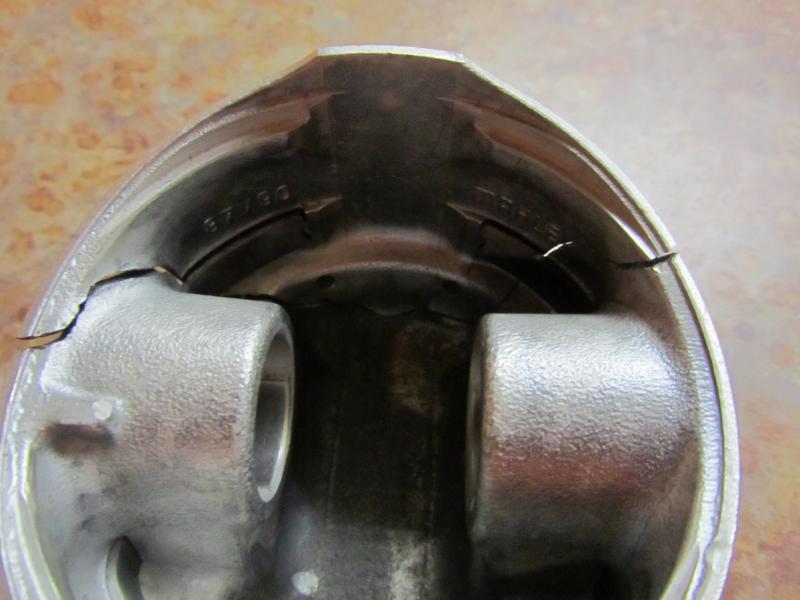
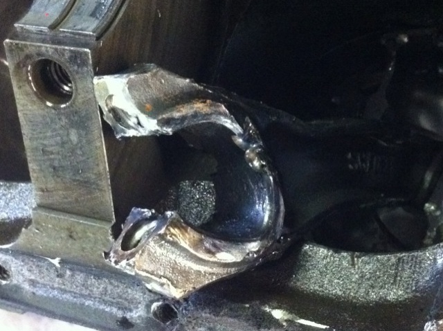
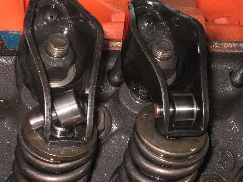
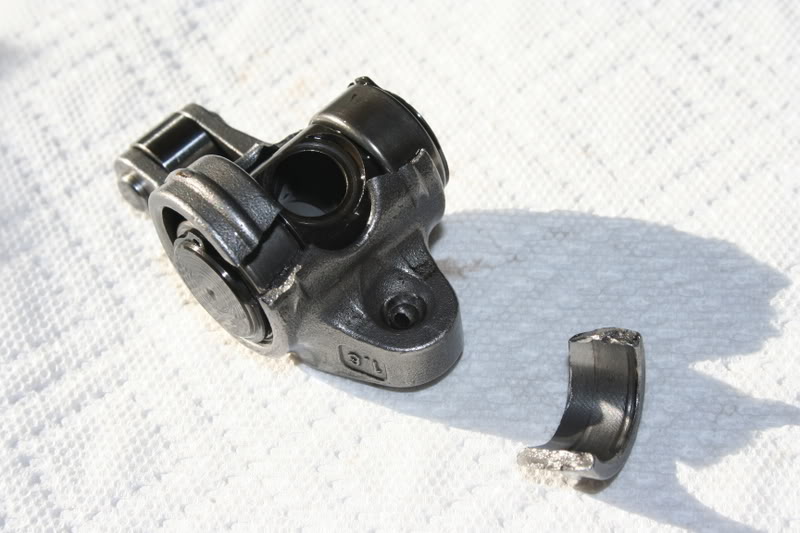
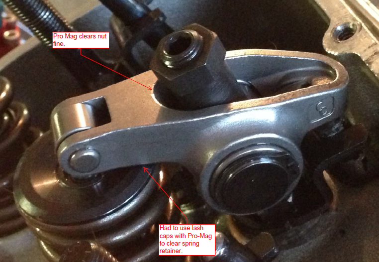
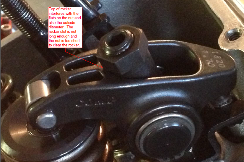
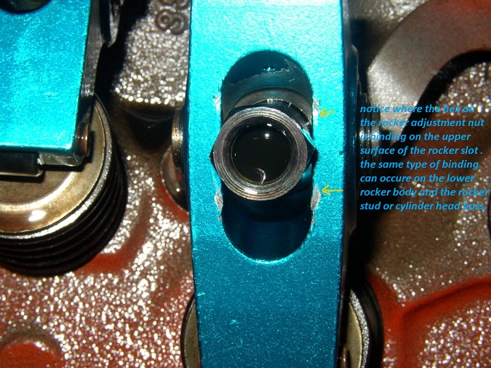
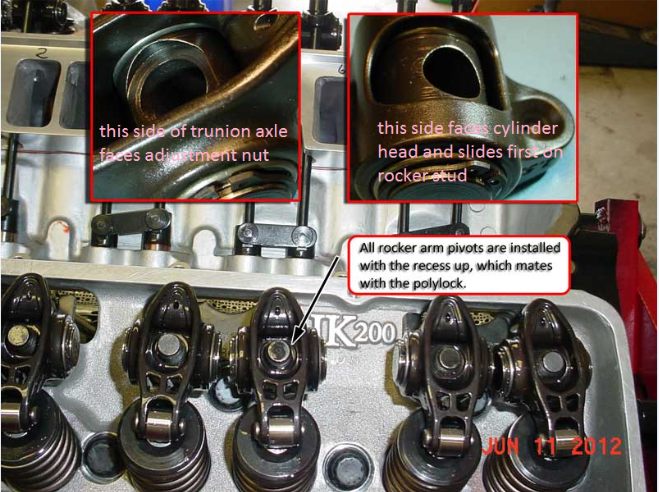
of the failed cam lobe & lifter problems were traced to a failure to check clearances or correct valve train geometry issues , like coil bind, rocker to rocker stud, or rocker to adjustment nut clearance, retainer to valve seal, clearances or rocker geometry, use of the wrong spring load rates for the application ,or failure to check valve train or push rods binding issues like rocker to retainer, push rods binding on guide plates or heads, etc. before they became an issue.
about

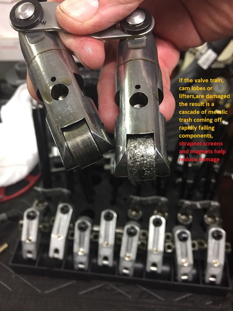
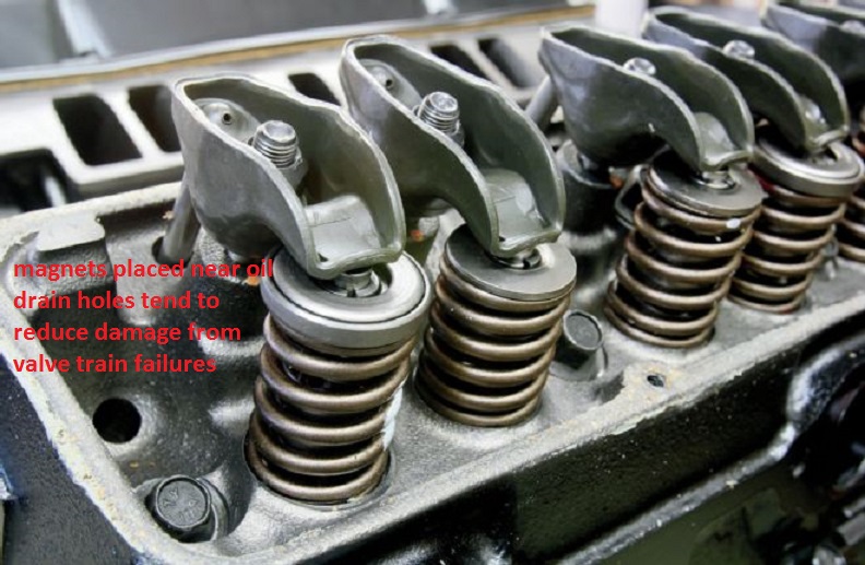
10% were traced to failure to remove metallic or other trash, generated by a previous cam failing from the engines internal oil passages, or failure to carefully clean the engine before installing the new cam, and components, ( use of shrapnel screens and magnets help a great deal in this but can,t remove all trash as some is non-magnetic)

5%
to low quality components, or miss matched parts, like the wrong spring load rates for the application, and perhaps

15% of the failures due to using the wrong lubricants , or not nearly enough moly cam lube on the lobes and lifter bases or setting up the oil supply system correctly, or use of a high quality oil and filter, and a failure to change that oil and filter regularly after the first few hundred miles , the remaining
10% were from unknown causes but more than likely due to a failure to correctly break in the cam, or properly adjust the valves before the engine break-in process or carefully check and re-adjust the lifters rapidly during the break-in process
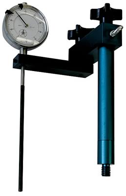
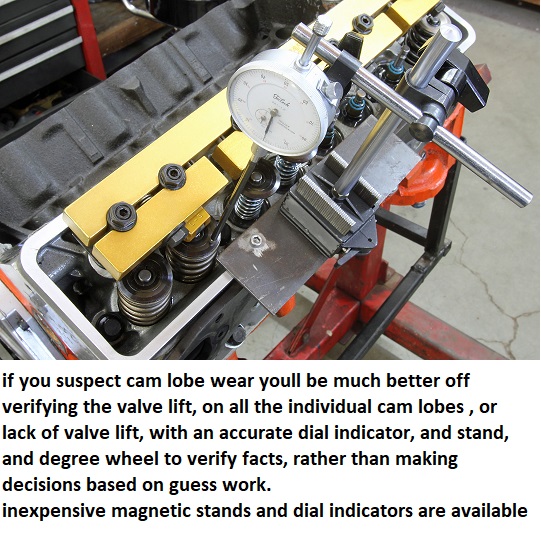
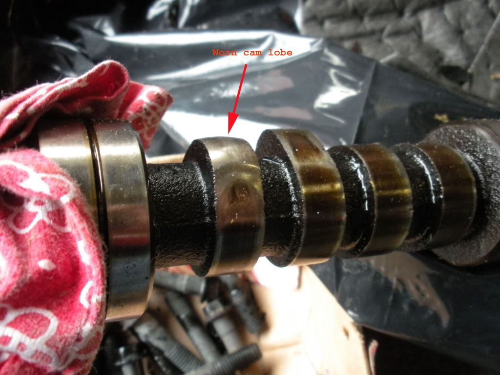
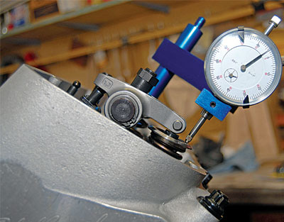
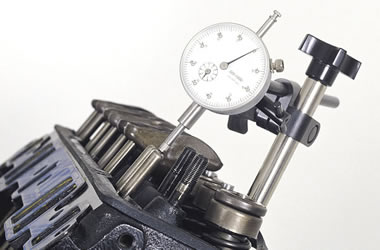
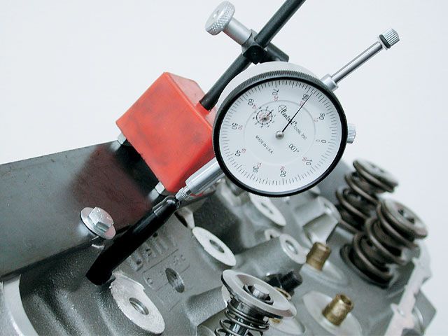
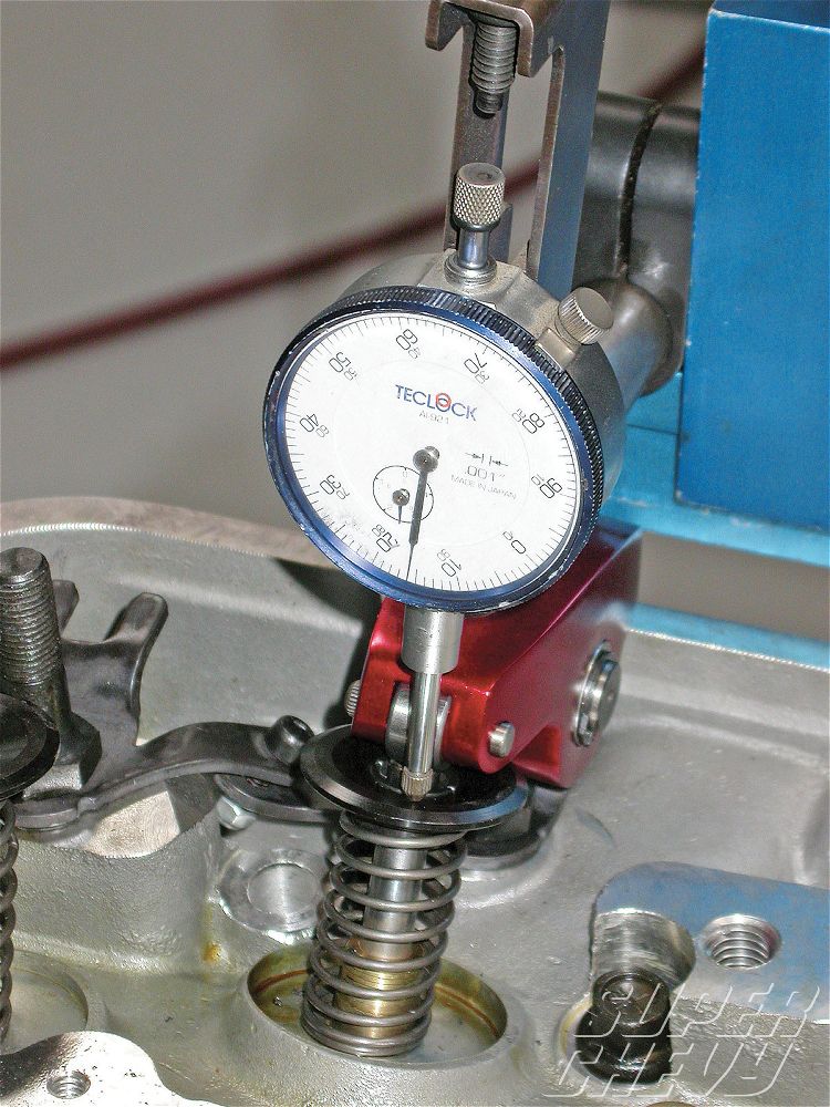
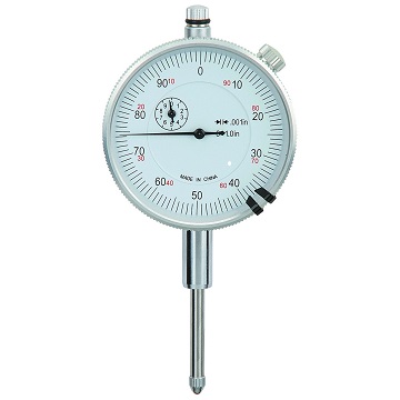
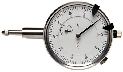
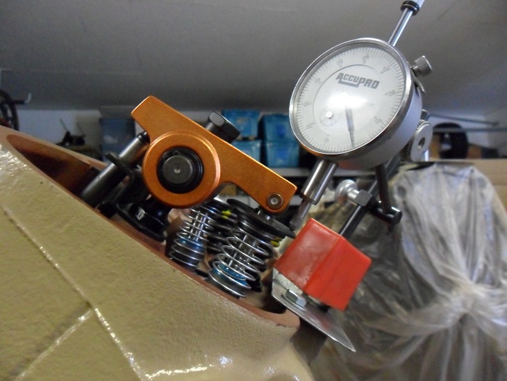
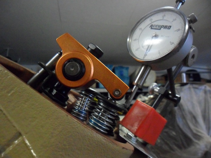
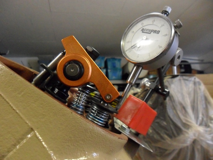
If you suspect a worn cam lobe, checking the cams lobe lift with a dial indicator on the valve spring retainer vs the other lobes would certainly provide useful related info.
knowing vs guessing helps in making decisions wisely

http://www.summitracing.com/parts/pro-66830/overview/


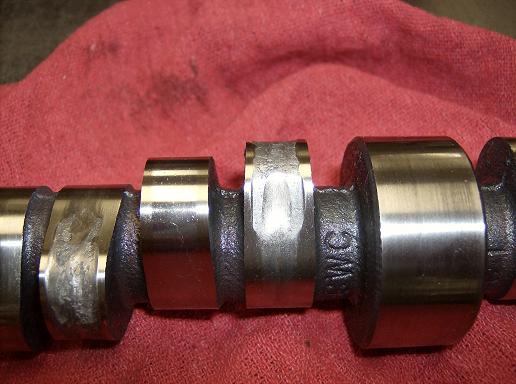
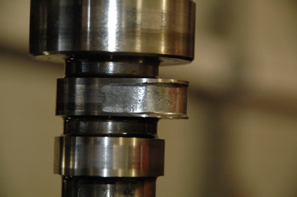
It is when they stop spinning that the camshaft and lifters fail and become a lathe.

index.php
index.php
index.php
index.php


pro-66830_cp.jpg

liftc1f.jpg

worn5.jpg


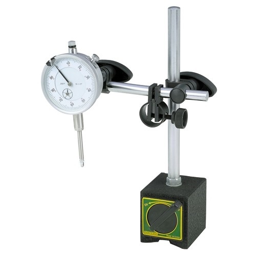
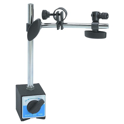
https://www.harborfreight.com/multipositional-magnetic-base-with-fine-adjustment-5645.html
bv93fans.jpg

https://www.harborfreight.com/catalogsearch/result/index/?dir=asc&order=EAScore,f,EAFeatured+Weight,f,Sale+Rank,f&q=indicator+stand


read this thread also
http://garage.grumpysperformance.com/index.php?threads/oil-system-mods-that-help.2187/

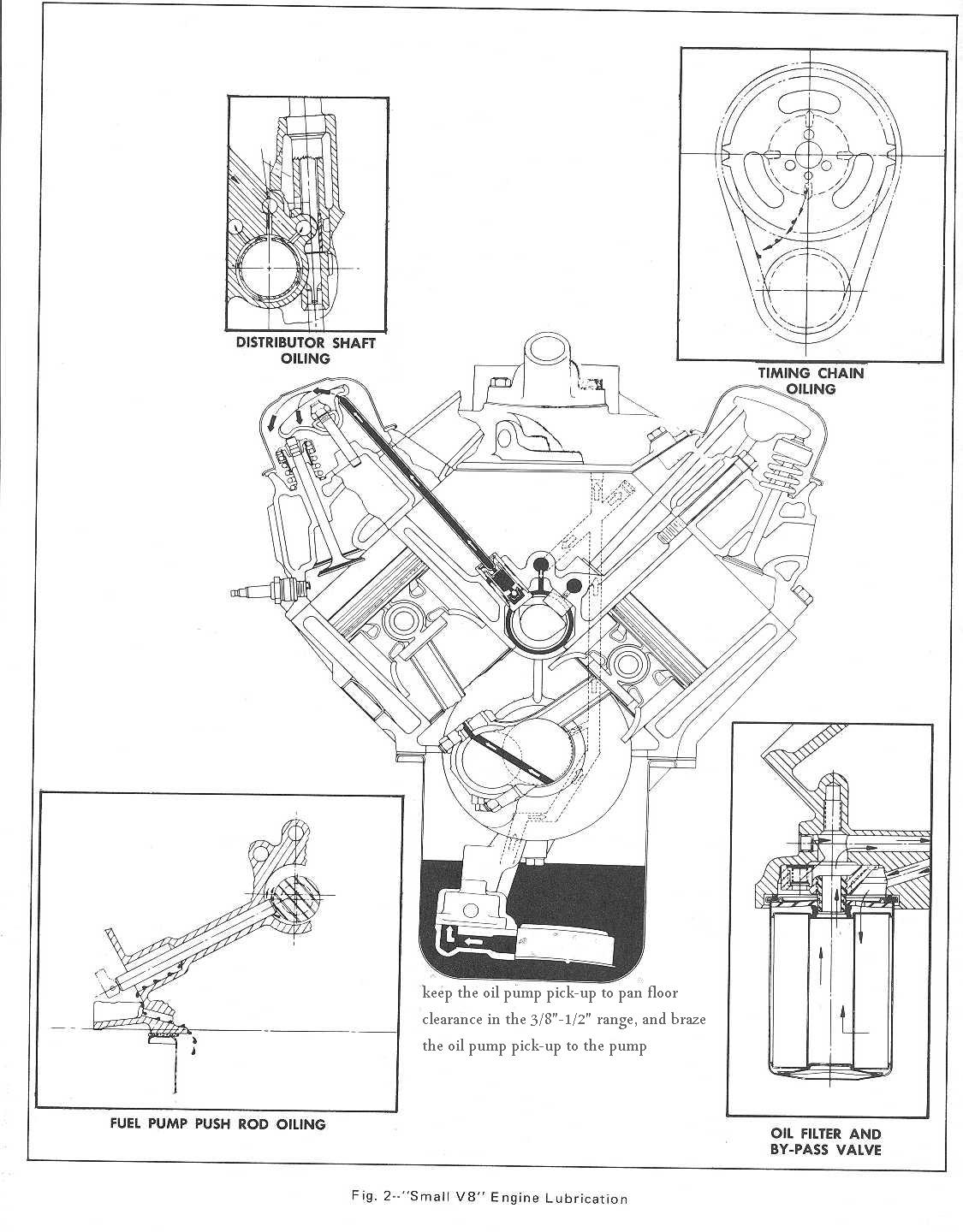
the rotating assembly bearings ,wrist pins and complete valve train,valve springs, lifters, valves and valve guides and the pistons and rings are where a great deal of the engine heat is generated, and those components are initially cooled with oil flow that absorbs and transfers the heat collected , and transported from those components to the block and coolant, so having a constant flow of pressurized oil flow over those parts are mandatory for maximum durability.thus adding a larger capacity baffled oil pan and an oil cooler will generally enhance and extend an engines life span. Its a good idea TOO ALWAYS ask detailed questions as to the best , and most durable parts combination they have available, for your intended application, from your cam suppliers tech department


http://garage.grumpysperformance.com/index.php?threads/oil-system-mods-that-help.2187/

http://garage.grumpysperformance.co...sion-and-oil-cooler-increases-durability.176/

http://garage.grumpysperformance.co...ck-chevy-gen-v-vi-to-adjustable-rockers.4564/
links worth reading thru


BEFORE TRYING TO BREAK IN YOUR CAM!
http://www.cranecams.com/pdf-tech-tips/cam_failure811.pdf


http://garage.grumpysperformance.co...e-springs-and-setting-up-the-valve-train.181/

http://garage.grumpysperformance.co...oil-passages-and-improved-oil-flow-mods.3834/

http://www.drivenracingoil.com/news/dro/training-center/articles/zinc-in-motor-oil/


http://johncalliesinc.com/morel_products.php

http://www.hotrod.com/how-to/engine/ctr ... ubricants/

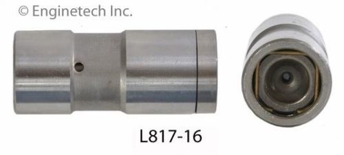
btw the best deal I found lately on basic hydraulic flat tappet lifters
http://www.summitracing.com/parts/sum-ht817/overview/
ZDDP_Additives06.jpg


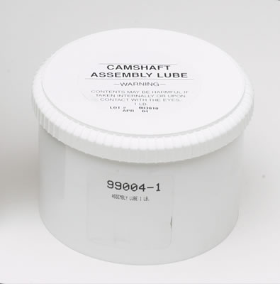
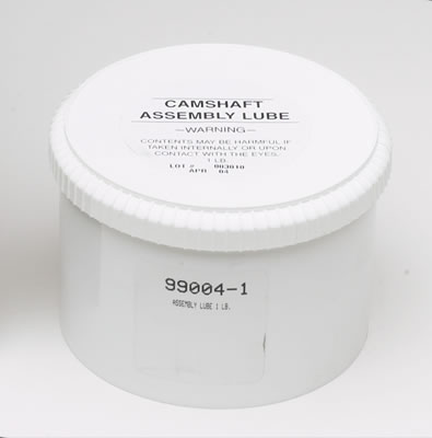
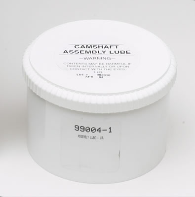
HERES A FEW OF THE OILS I TRUST, coat flat tappet lifters and cam lobes with crane moly assembly paste lube
crn-99004-1_w.jpg

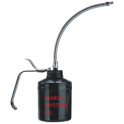
I usually use 6-7 quarts of oil and 1 quart of marvel mystery oil added in my oil pan 11 quart oil pan and oil cooler system capacity

10W30 Valvoline VR1 Conventional Racing Oil
10W30 Valvoline NSL
10w30 Castrol GTX conventional,
10w30 mobile 1
10w30 KENDAL racing oil
zddp.jpg

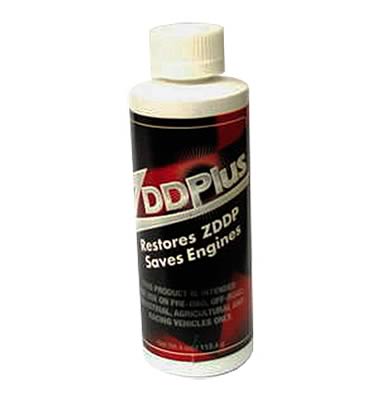
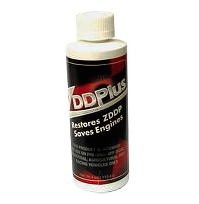
and heres a good break in additive for flat tappet lifter cams
http://www.summitracing.com/parts/CRO-86092
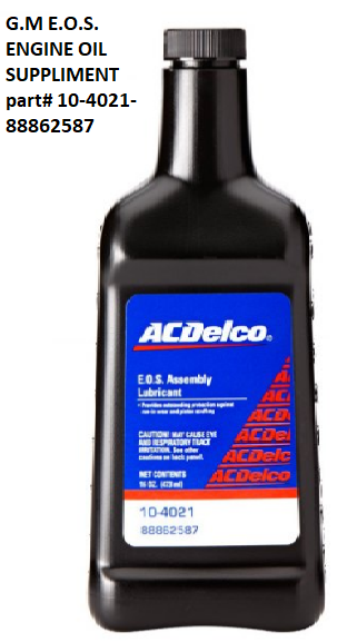
http://www.acdelco.com/auto-parts/v...engine-oil-supplement-assembly-lubricant.html
eos.png

READ THRU THESE LINKS
http://garage.grumpysperformance.co...il-properties-related-to-zddp-detergent.4793/

http://garage.grumpysperformance.co...h-the-oil-when-a-cam-failed.11542/#post-53323

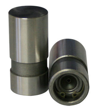
the better quality hydraulic and solid flat tappet lifters have hardened bases
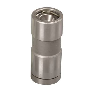
hardface.jpg

lobelif.png


iskysolidlift.jpg

Mobile1Oil-1.jpg

Mobile1Oil-2.jpg

hylifters.jpg

camoil.gif

wornlifters.jpg

camlobec.jpg

trashbeare.png

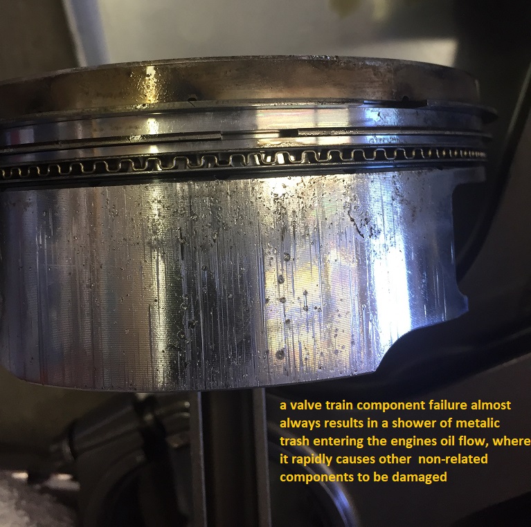
it only takes a few seconds running a new engine for an improperly installed cam , lifters and valve train, during the break-in process to generate teaspoons of metallic trash that ,once in the engine oil flow ,rapidly destroys bearings if the clearances ,spring load rates or valve train geometry is wrong

If your not getting oil flow, at the rockers,youll still need to verify the oil feed holes line up and are not blocked and the rockers adjusted correctly, try backing off on the adjustment nut as the engine idles to the point the rocker clicks noticeably then slowly tighten just to the point the noise stops , then add only a 1/4 turn, and see if that doesn,t cure the oil feed issue


Id also point out that you'll want to lubricate any valve you install in a valve guide and verify the valve train clearances very carefully, and use the correct valve springs and add the correct valve seals installed

Isky claims that the Comp XE cams violate the 47.5% rule. The 47.5% rule applies to flat tappet cams for SBCs with 1.5 rockers but the concept is still the same for other configurations where the designs are "on the edge" or "over the edge" for lobe intensity. For 1.5 ratio SBCs, the duration at .050 must exceed 47.5% of the total valve lift or your asking valve train problems. For example, take a Comp Cams Magnum 280H, with 230 duration and, 480 lift...230/.480 = 47.9% which exceeds 47.5% therefore would not pose a threat to components. We do not regularly hear about the older, safer HE and Magnum designs rounding off lobes anywhere near as often as the XE cam designs. Unfortunately, some of the Comp Cams XE dual pattern lobes break this 47.5% rule on the intake side so they are likely to be problematic. The design has "steeper" ramps that are too quick for durability and reliability according to other cam manufacturers. They will wipe lobes in a heart beat especially if you have not followed the proper break-in procedure. Other designs are more forgiving during break-in and less likely to fail.
generally its best to purchase all the listed components in a cam installation kit (cam, lifters,valve springs, etc. ) from a single manufacturer as mixing parts, sources or brands,
(KEEP YOUR RECEIPT'S AND IDEALLY BUY THE PARTS AT THE SAME TIME!)

allows the cam manufacturer to void the warranty
, even if the parts in the kit they sell are either identical or inferior to,
the individually purchased components you individually sourced. keep in mind most manufacturers will have tested parts compatibility ,
so they are reasonably sure the components they sell in the kit will work, that can,t be always assumed,
with randomly matched parts even if those parts are good quality.


READ THIS THREAD


http://www.nitemareperformance.150m.com/ZDDP.html


http://s572.photobucket.com/albums/ss16 ... mpCams.flv

http://www.circletrack.com/techarticles ... index.html

adding e.o.s. to your oil is beneficial during the cam break-in, but it tends to leave deposits that can cause detonation over time in the combustion chambers
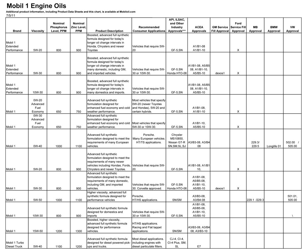
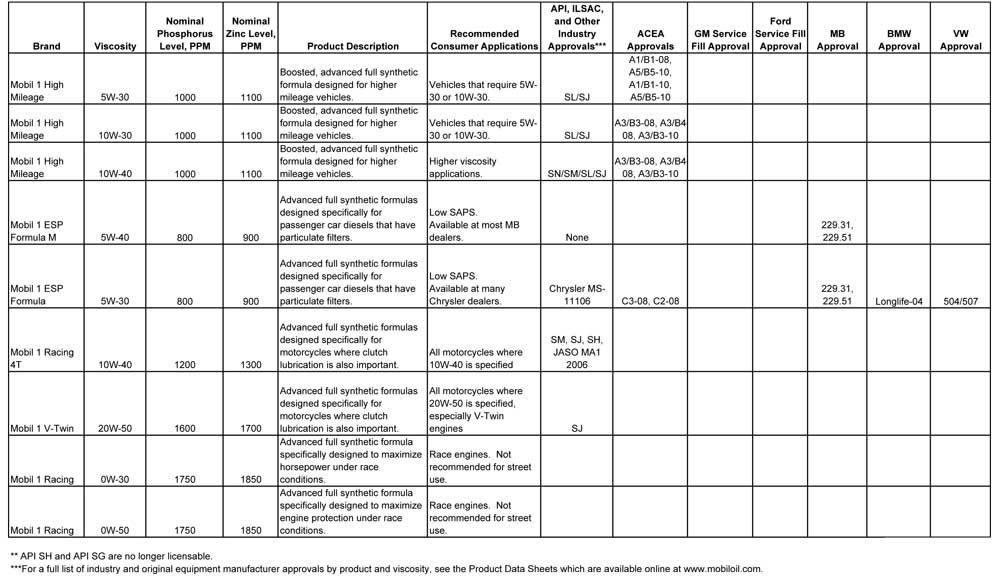
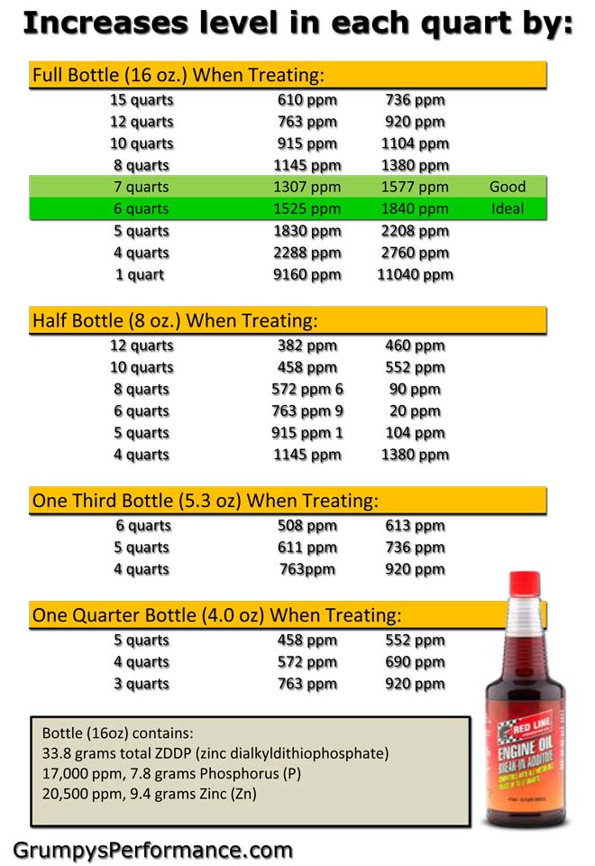
NOTE:1200PPM-1400PPM ZDDP IS THE GENERAL RECOMMENDED MINIMUM ZDDP LEVEL FOR FLAT TAPPET CAMS WITH THE HOT CAMS WITH HI SPRING RATES BEING AT THE HIGHER 1350-1400PPM
CAST CAM CORES ARE NOT DESIGNED TO HANDLE OVER ABOUT 130lbs SEAT and 400lbs OPEN SPRING LOADS YOU NEED A BILLET CAM CORE FOR DURABILITY IF THOSE LIMITS ARE EXCEEDED
ID suggest you read these links
http://www.enginebuildermag.com/Article ... fters.aspx
http://automotivemileposts.com/zddp.html

http://zddppluscentral.com/

http://www.crower.com/misc/product/dl/ZDDP_clr.pdf
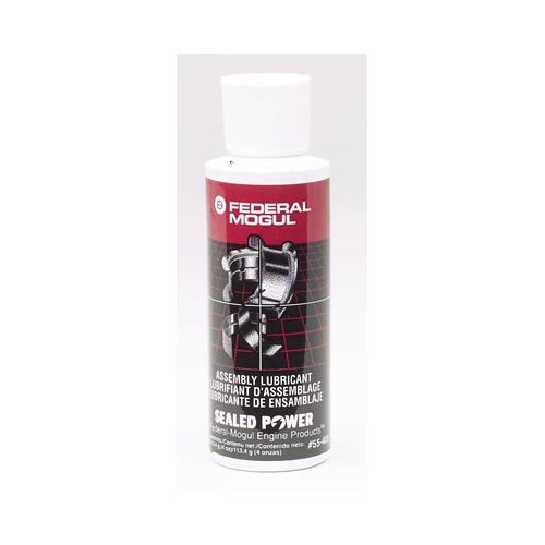
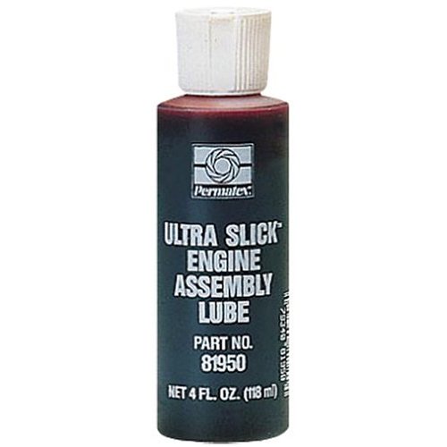
crcassembly.jpg

fedassembly.jpg

permassembly.jpg

cl1.jpg

cl2.jpg

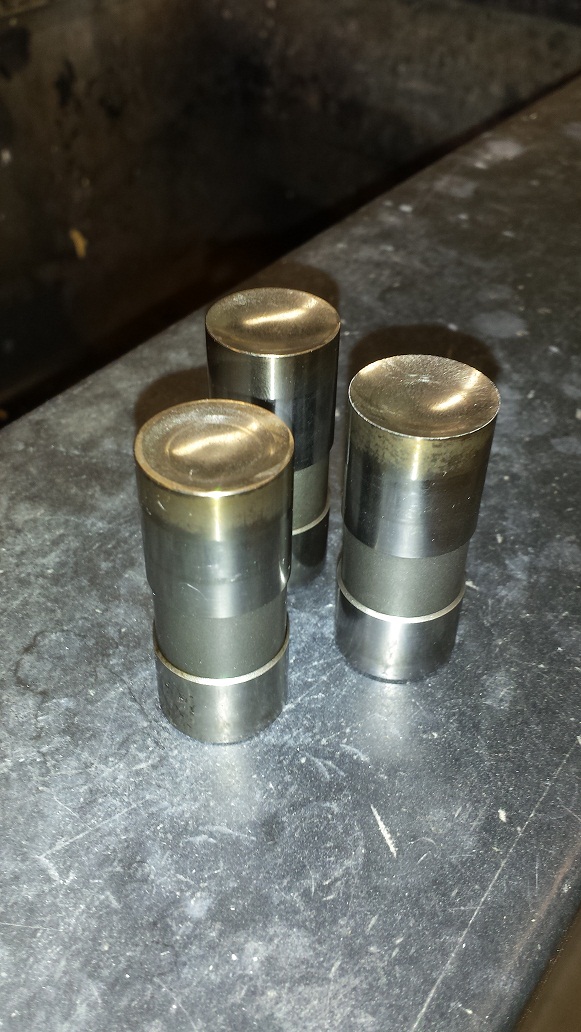
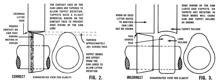
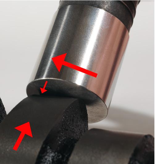
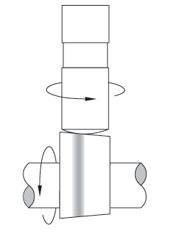
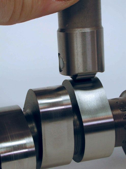
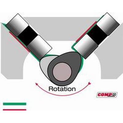
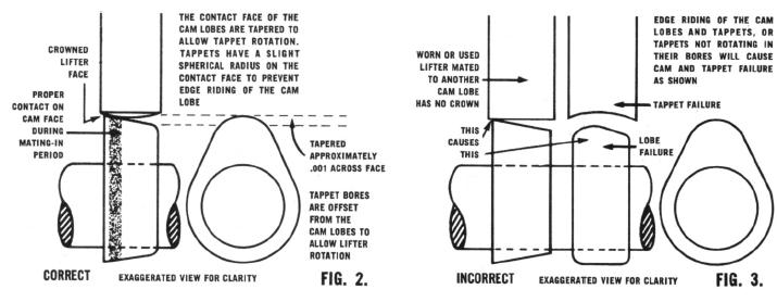
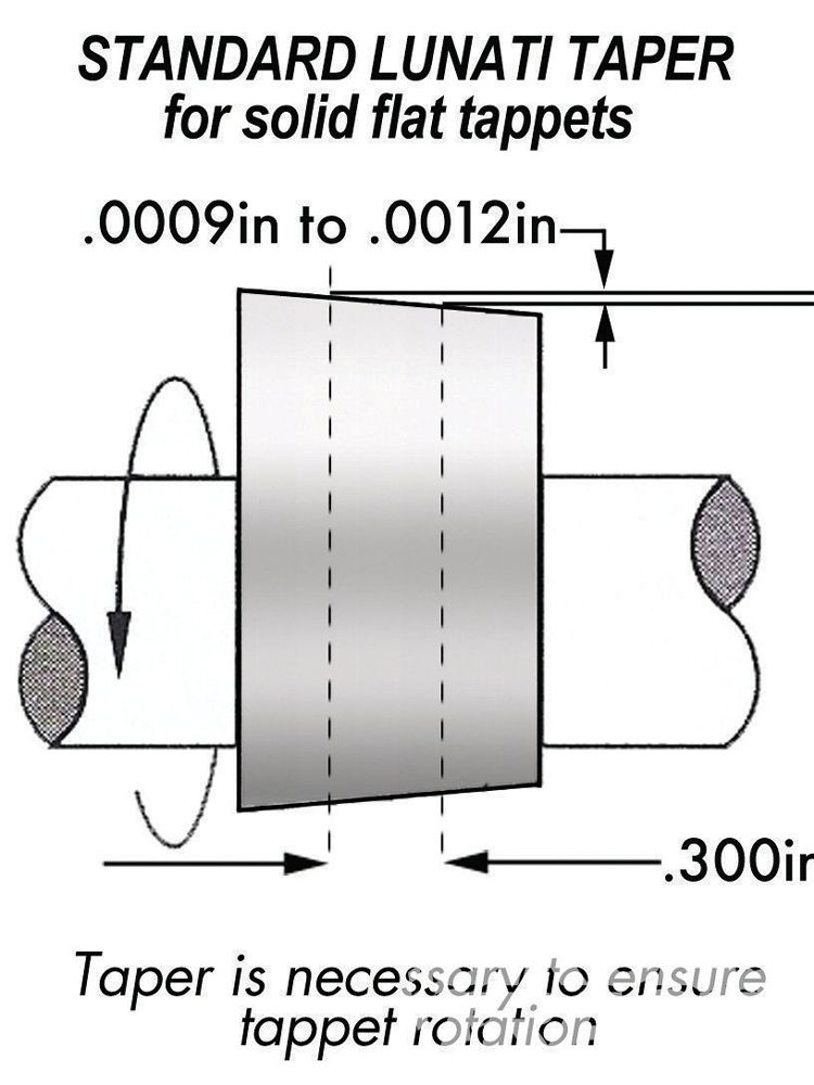
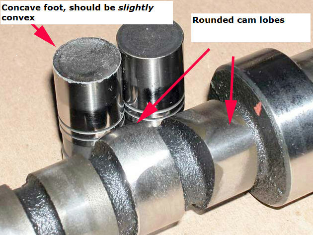
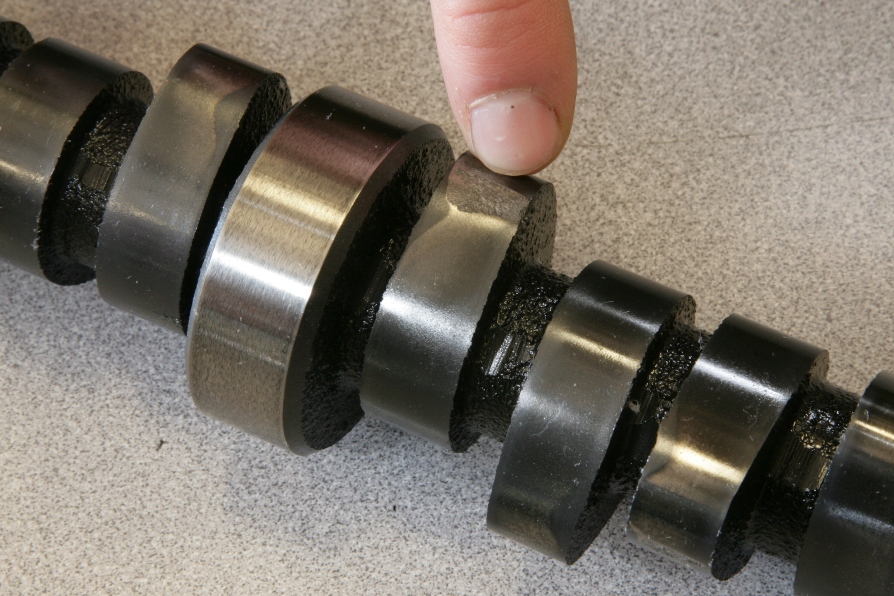
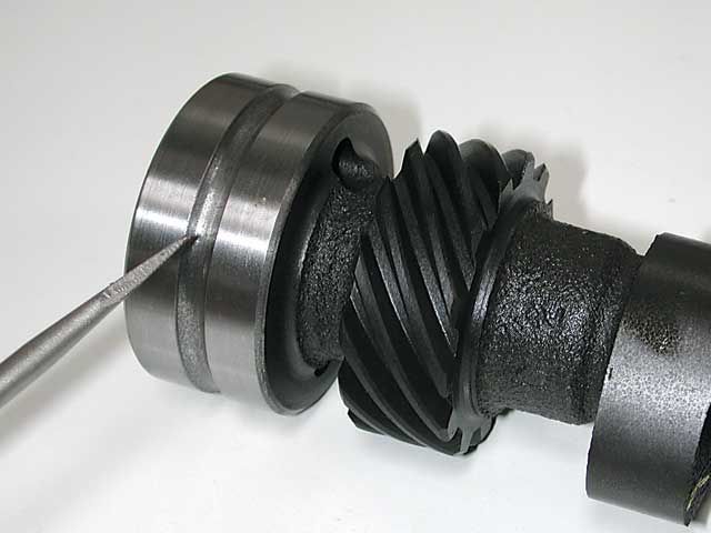
the slight bevel on the cam lobe and the slight convex surface on the lifter base in combination with the lobe center-line being slightly offset from the blocks lifter bore results in the lifter rotating in its bores as the lobe rotates under the lifter base
cl3.jpg


https://www.summitracing.com/parts/crn-99004-1

31ccRUmfbmL._SL500_AA300_.jpg

very good
molypaste.jpg

very very good
molysp3.JPG

molysp2.JPG

molysp1.JPG

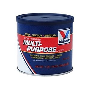
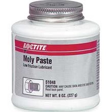
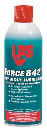
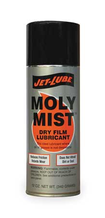
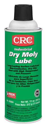
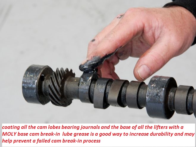
pre-spraying all bearing and valve train components with a moly based spray, helps embed micro moly lubricants in the metallic surface micro fissures , a good paste lube like cranes assembly lube over the spray surface helps insure a good lubricant surface coating, that is far stronger than just the ZINC and PHOSPHATES in oil
read this

Molybdenum Disulfide (Moly) has been used for decades in lubricating pastes and greases because it is slippery and forms a protective coating on metal parts:

Single Molecule of MolyMoly exists as microscopic hexagonal crystal platelets Several molecules make up one of these platelets. A single molecule of Moly contains two sulfur atoms and one molybdenum atom. Moly platelets are attracted to metal surfaces. This attraction and the force of moving engine parts rubbing across one another provide the necessary thermochemical reaction necessary for Moly to form an overlapping protective coating like armor on all of your engine parts. This protective armor coating has a number of properties that are very beneficial for your engine.

The Moly platelets that make up the protective layers on your engine surfaces slide across one another very easily. Instead of metal rubbing against metal, you have Moly platelets moving across one another protecting and lubricating the metal engine parts.

This coating effectively fills in the microscopic pores that cover the surface of all engine parts, making them smoother. This feature is important in providing an effective seal on the combustion chamber. By filling in the craters and pores Moly improves this seal allowing for more efficient combustion and engine performance.
This overlapping coating of Moly also gives protection against loading (perpendicular) forces. These forces occur on the bearings, and lifters. The high pressures that occur between these moving parts tend to squeeze normal lubricants out
http://streetmuscleaction.com/wp-conten ... reakin.pdf

spraying the cam surface with moly and then coating it with moly assembly lube before installation tends to help.
S00200.jpg

lifter1jpg.jpg

http://www.globalindustrial.com/gcs/pro ... paignId=WZ

DS-700006.jpg
http://www.circletrack.com/enginetech/c ... index.html

http://www.compcams.com/Community/Artic ... 1578676008

http://www.circletrack.com/enginetech/c ... index.html

http://www.corvetteactioncenter.com/tech/oil/index.html

http://www.rehermorrison.com/techtalk/47.htm

http://www.cam-shield.com/index.html


http://www.pbm-erson.com/uploads/cat%5B ... CEDURE.pdf

http://www.hotrod.com/techarticles/cams ... index.html


ctrp_0807_03_z+flat_tappet_camshaft+engine_lubricants.jpg


http://www.hotrod.com/techarticles/engi ... index.html

the assembly lube, oil and clearances are critical to durability


you might want to read thru this

preventing cam & lifter break-in failures


http://www.pbm-erson.com/uploads/cat%5B ... CEDURE.pdf

http://www.corvetteactioncenter.com/tech/oil/index.html

OPTIONS

it should be rather obvious that theres options, cam failures are usually the result of incorrect CLEARANCES or too much SPRING PRESSURE or LACK of ADEQUATE LUBRICATION,USE DECENT MOLY CAM LUBE, and decent quality oil, adding MAGNETS to trap metallic CRUD HELPS, be sure to change your oil filter and oil after the first 3-4 hours or 100 miles as theres bound to be crud and assembly lube trapped in the oil and filter
HRDP_0606_01_z+flat_tappet_cam_tech+broken_lifter.jpg


the old familiar stuffs Part #1052367 is getting hard to find
E.O.S. was discontinued but.....
http://www.sdparts.com/product/1052367/GMEngineOilSupplimentEOS16ozBottle.aspx
the new stuff...
http://www.acdelco.com/html/pi_vehcare_lub.htm
(use the drop down menu)
Part 10-106
12371532
E.O.S. Assembly Lubricant (1 pint)

its still available if you know where to look, most but not all parts counter guys will know this but youll run into a few who just insist its not available


http://www.cranecams.com/?show=promo&id=48


btw MOLY base lubes are your first and best break-in lube during the first few minutes

http://www.cranecams.com/index.php?show=browseParts&lvl=2&prt=15

http://www.cranecams.com/pdf/548e.pdf

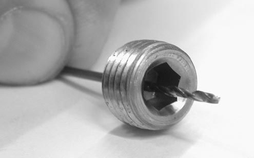
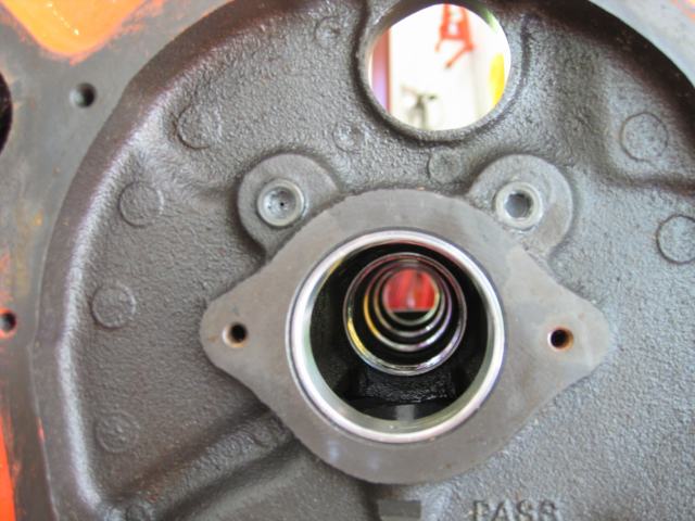
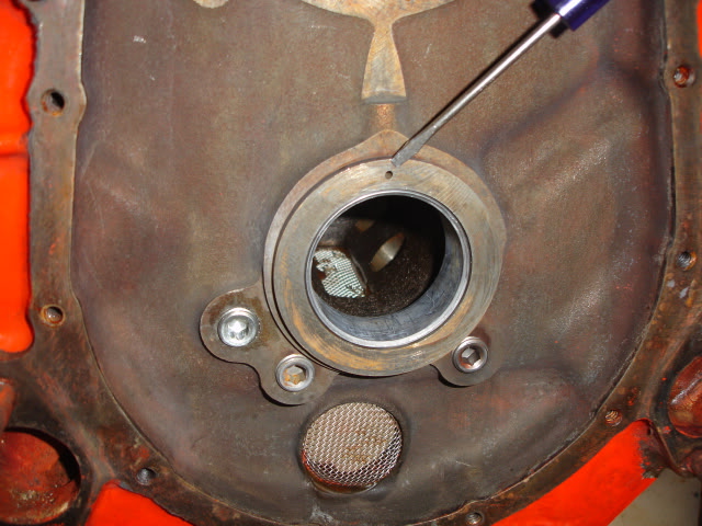
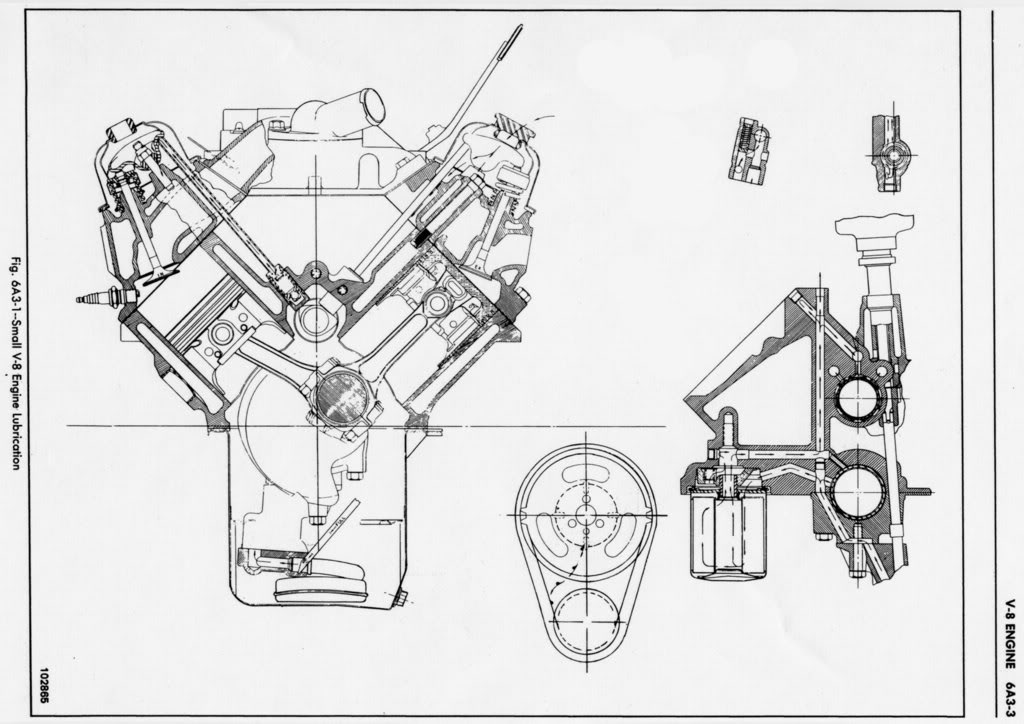
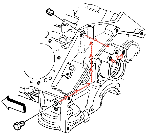
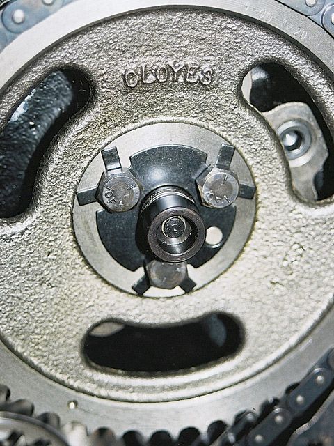
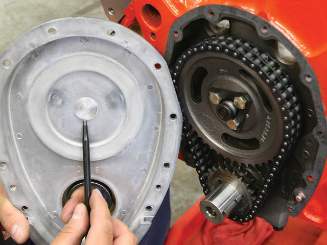
its also a real good idea to drill the pass side oil plug under the timing cover with a .030-.035 drill so oil constantly sprays on the timing chain during use,and while IM discussing cam timing sets Id say that about 90% of the time a good CLOYES timing chain set should be used on street cars vs a gear drive if that's one option your thinking about.
drillplug.jpg

enginerebuild87.JPG

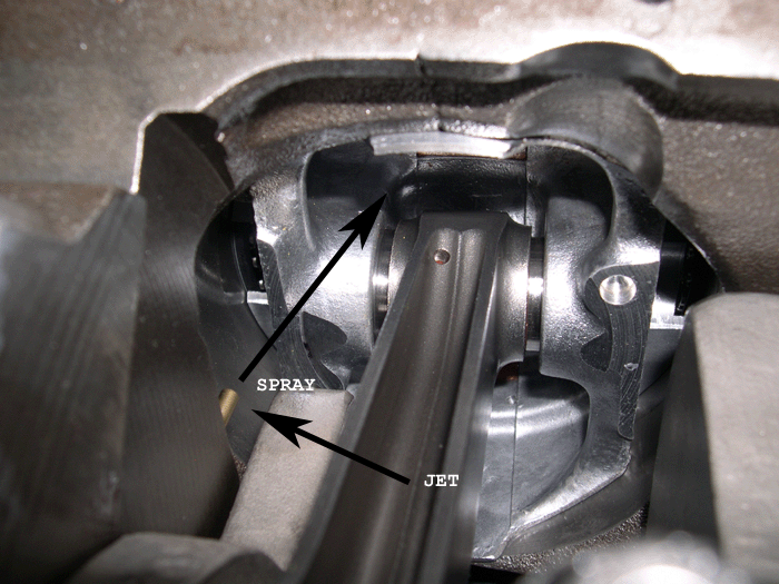
drilling the pass side oil passage plug with a 1/32" bit so oil constantly sprays on the timing gears helps extend chain and gear life.


CRANES Super Lube Break-In Concentrate is an anti-wear additive formulated with a high concentration of special zinc dithiophosphate to provide sustained protection against cam lobe and lifter scuffing and wear. This oil supplement is to be added to the engine oil for the initial break-in period after the installation of a new camshaft and lifters.
Now it should be obvious that reducing the pressure at the contact point between the lifter and the cam lobe will tend to reduce the tendency for lifter & lobe wear, and increasing the coolant flow at that point helps, so its generally a good idea to remove the INNER spring on DUAL spring valve trains during the break -in process, to reduce pressures while the parts lap in, and a few minutes with some 1000grit sand paper to remove burrs from the lifter edge sure helps in most cases

Part No. 99003-1 -- 8-ounce container
p43452_image_large.jpg

a decent BILLET cam core and quality roller lifters will prevent a great deal of cam lobe wear issues
rollerlifter.jpg

even roller cams can wipe out lobes if the valve train components or valve train lubrication, geometry is not set up correctly
camlobe1.jpg

camlobe2.jpg

IF youve ever wondered what happens in SECONDS to a cam lobe if the roller lifter turns sideways in its bore if it has the dog bone or link break...
looserol1.jpg

looserol2.jpg


DSC02157.jpg

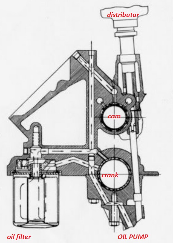
a small hole 1/16" intersecting the oil feed passage to provide pressurized oil to the rear of the timing gear won,t hurt, and tends to reduce block wear
OBVIOUSLY YOULL WANT THE CORRECT VALVE SPRINGS

http://www.competitionproducts.com/1500-1585-OD-Valve-Springs/products/2631/1/0

https://www.summitracing.com/search/part-type/valve-springs

https://www.iskycams.com/cart/valve-springs-c-99.html

http://www.cranecams.com/userfiles/file/334-343.pdf

https://www.racingsprings.com/Valve-Spring/Store/13

http://www.lunatipower.com/Category.aspx?id=23

http://www.pspring.com/products/engine-valve-springs/

http://www.competitionproducts.com/Valve-Springs/departments/49/

http://psisprings.com/products/

http://www.compcams.com/Products/CC-'Valve Springs By Usage'-0.aspx

http://www.racingsprings.com/Beehive-Valve-Springs

https://www.supertechperformance.com/valve-springs-p109

http://www.cvproducts.com/index.php/psi-springs/

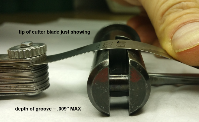
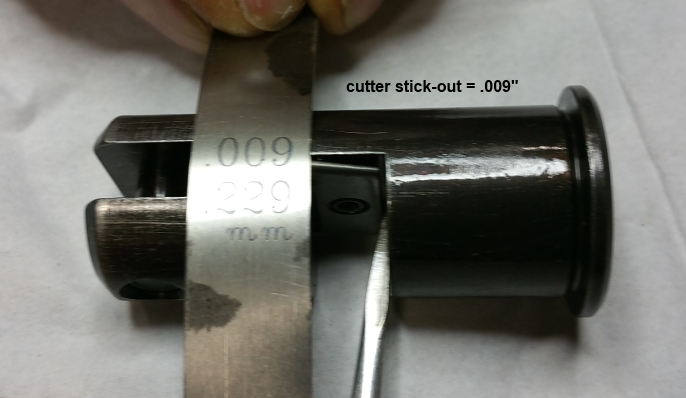
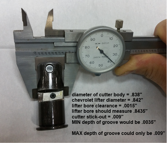
lifterboretool.jpg

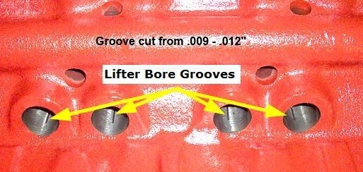
lifterboregroove.jpg


or if your into serious mods
0601_06.jpg

sprayjet.gif


have you seen this
zddp.jpg


http://www.summitracing.com/parts/CRO-86092

hrdp_0412_06_z+big_block_chevy_engine+rocker_arms.jpg


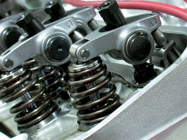
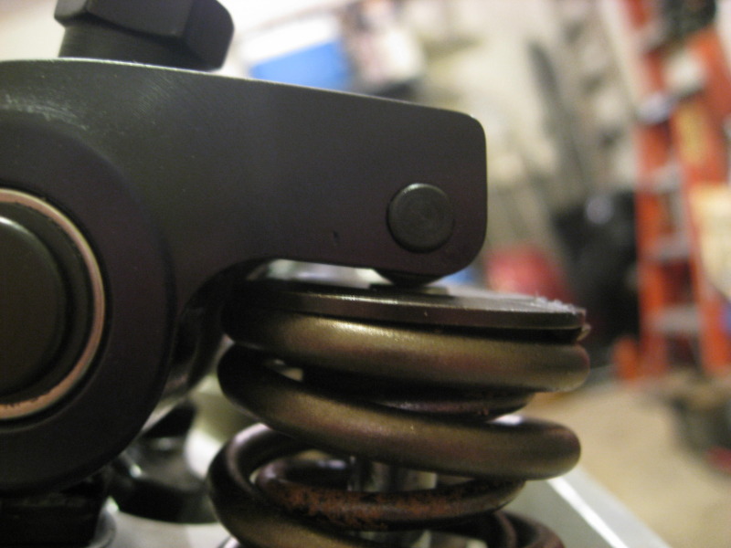
BEEHIVE SPRINGS and FORGED STEEL ROCKERS GIVE A GOOD DEAL MORE ROCKER TO RETAINER CLEARANCE
rockertoretainer.jpg


BTW BEFORE SOMEONE ASKE'S, YOU CAN NOT USE A ROLLER TAPPET ON A FLAT TAPPET CAM OR A FLAT TAPPET LIFTER ON A ROLLER CAM< BECAUSE...of several reasons, the main one is that, flat tappet cams have BEVELED LOBES, roller cams have PARALLEL LOBE RAMPS, you can NOT mix and match, the lobe on either cam will quickly DESTROY the other type of lifter design, if its mistakenly installed

lifter1jpg.jpg

camwear.jpg

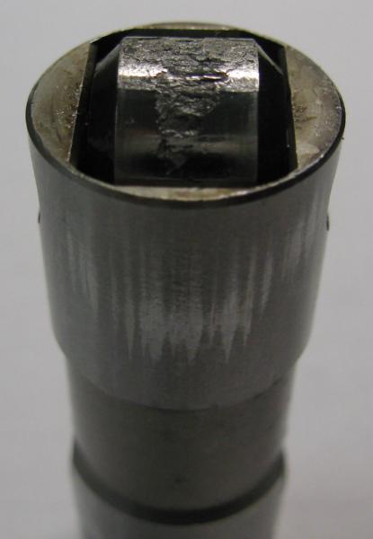
USED LIFTERS TEND TO BE A BAD BET ON CAM DURABILITY
FLAT TAPPET
race-engine-cams.jpg


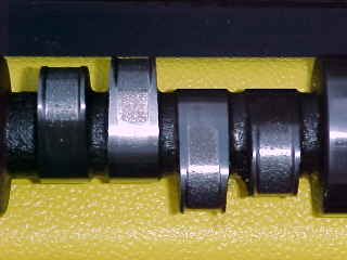
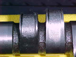
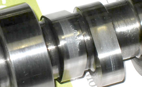
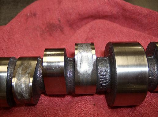
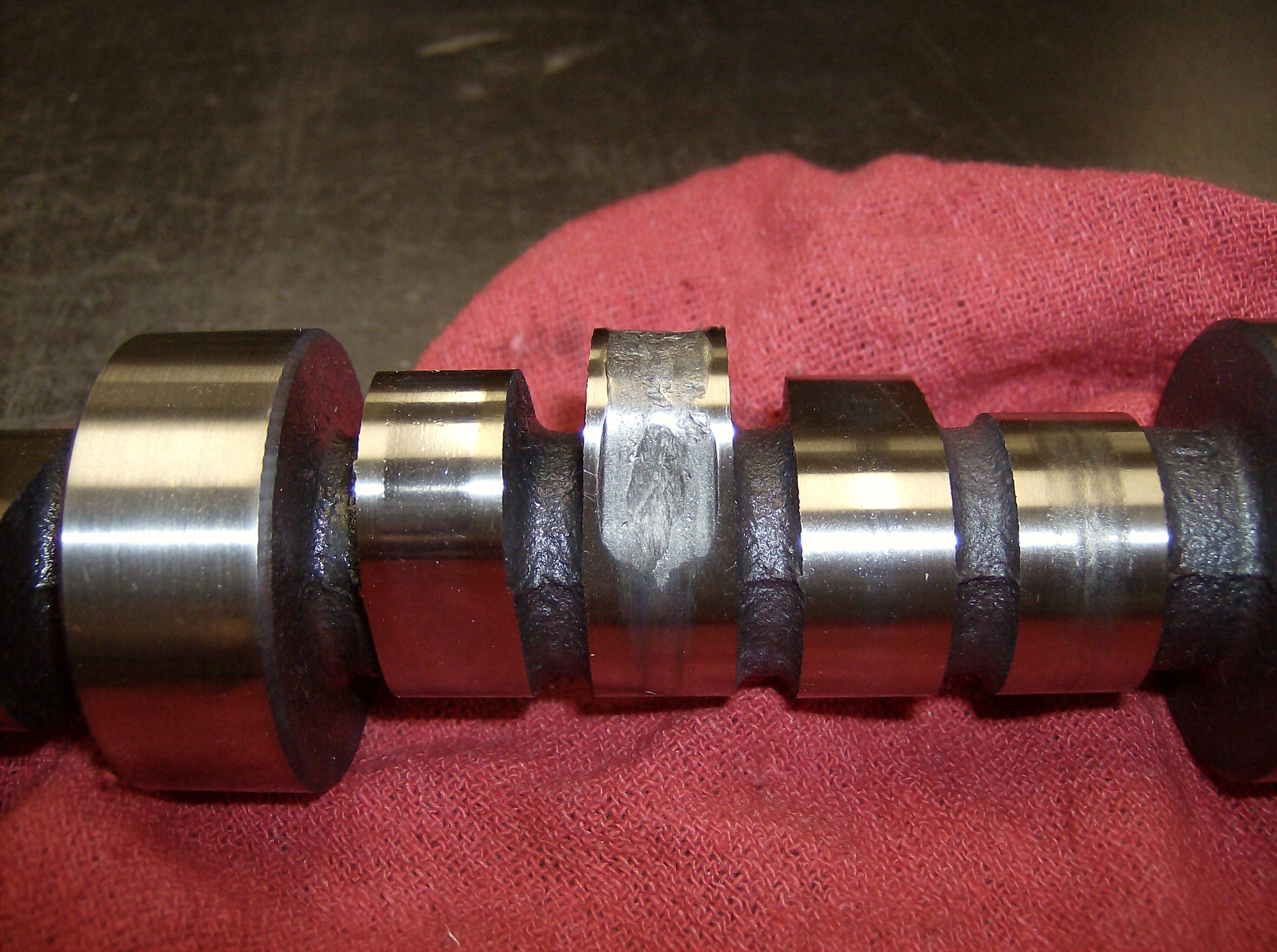
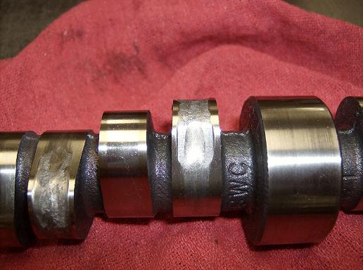
a quality hardened cam with proper lube won,t wear like this first two picture's, but notice the lifter stayed on track
camlobe1.jpg

camlobe2.jpg


hardened cam lobes and high quality hardened roller lifter wheels have very low rotational friction,
and as long as the valve train stays in its designed limitations and the inertial loads don,t over come the valve springs ability to maintain constant lifter to lobe contact,
and theres a constant bath of cooling oil flowing over the contact areas,
rates of lifter to lobe contact and wear are minimal or basically non-existent over any reasonable time frame
rollerlifter.jpg

ROLLER CAM

use of the best friction reducing MOLY assembly lube plus the better oils, helps reduce cam lobe wear issues
proper clearances ARE MANDATORY
Moly Basics
Molybdenum Disulfide

posting.php?mode=edit&f=52&p=34840
zddp.jpg

BRAKE IN LUBE
http://www.summitracing.com/parts/CRO-86092
Molybdenum is a very hard metal with a number of industrial uses.
It is combined with chromium in steel to make the steel harder and more resistant to bending. Most of the bicycle frames produced today use chromium and molybdenum steel. Because the steel is so much harder, the manufacturers can use less, thereby making the frame lighter.

Molybdenum Disulfide (Moly) has been used for decades in lubricating pastes and greases because it is slippery and forms a protective coating on metal parts.

Moly exists as microscopic hexagonal crystal platelets Several molecules make up one of these platelets. A single molecule of Moly contains two sulfur atoms and one molybdenum atom. Moly platelets are attracted to metal surfaces. This attraction and the force of moving engine parts rubbing across one another provide the necessary thermochemical reaction necessary for Moly to form an overlapping protective coating like armor on all of your engine parts. This protective armor coating has a number of properties that are very beneficial for your engine.

squeeze4.png


The Moly platelets that make up the protective layers on your engine surfaces slide across one another very easily. Instead of metal rubbing against metal, you have Moly platelets moving across one another protecting and lubricating the metal engine parts.

This coating effectively fills in the microscopic pores that cover the surface of all engine parts, making them smoother. This feature is important in providing an effective seal on the combustion chamber. By filling in the craters and pores Moly improves this seal allowing for more efficient combustion and engine performance.
nosqueeze.jpeg

This overlapping coating of Moly also gives protection against loading (perpendicular) forces. These forces occur on the bearings, and lifters. The high pressures that occur between these moving parts tend to squeeze normal lubricants out.


Eventually, there is metal to metal contact, which damages these moving parts and creates large amounts of heat. Fortunately, this is not the case with some lubricants.The layer of moly that forms on these moving surfaces can withstand pressures of 500,000 psi, without being squeezed out.

Engineers and scientists have tried for years to use Moly in motor oils but they had been unsuccessful because they could not find a way to keep Moly in suspension. Once Moly was put into suspension it would gradually settle out. It was easy to see it come out of suspension because a black sludge would collect on the bottom of the oil containers. In engines it would settle to the bottom of the crankcase or clog oil pathways and filters.

Engineers have overcome these obstacles. They have developed a process that keeps Moly in suspension and isn’t filtered out. Since that time the product has undergone extensive independent testing in labs and in the field for many years to insure that the product stands up to the rigorous needs of today’s engines. With the plating action of Moly reducing friction which reduces heat, this helps keep rings free from carbon buildup, prevents blow-by, decreases emission, and extends oil life.
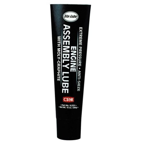
ASSEMBLY LUBE USED ON CAMS AND LIFTERS ROCKERS< BEARINGS ETC. like CRANE CAM LUBE, has molybdenum disulfide in assembly lube, that helps maintain a strong heat resistant high pressure lubricating support film on sliding surfaces, BUT assembly lube is NOT INTERCHANGEABLE WITH MOLY AXLE GREASE
which has other ADDITIVES, in some cases its mixed with non-compatible lithium grease base,
you must use a moly based assembly lube thats designed to mix with automotive oil to provide a strong surface film on sliding surfaces

http://en.wikipedia.org/wiki/Lithium-based_grease


marvel.jpg

asl1.jpg

crn-99004-1_w.jpg
 
Last edited by a moderator:
Re: cam wear, circle track mag article you need to rea
THERES BILLET AND TOOL STEEL CAM CORES AVAILABLE
http://www.callies.com/wp-content/uploads/2014/06/Cam-Core-Master-Price-Sheet.pdf
Callies Crankshafts Producing 8620 Billet Cam Cores
http://johncalliesinc.com/morel_products.php
Recieved notice today, that Callies, is producing billet cam cores for the camshaft industry. This has been in the making for about 1.5 yrs. Since Crane started to have problems, the owner of Callies, took a look at the equipment, but as far as I know only purchased the gear cutting equipment. Crane used to produce the the cams for the aircraft engine mfgs that Callies, makes crankshafts for and when Crane was going down the aircraft engine mfgs notified Callies ,that production of cranks was going to end until a cam mfg was found. So they now mfg and finish cams for aircraft engines and are solving the shortage of cores elsewhere. To me it's good to know that the mfg that makes cranks for aircraft engines also mfg cranks in our market. THEY ARE NOT SUPPLING CAMS ONLY CORES FOR FINISH TO THE CAM GRINDING COMPANYS
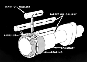
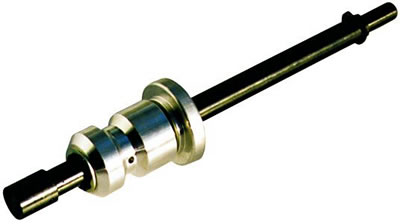
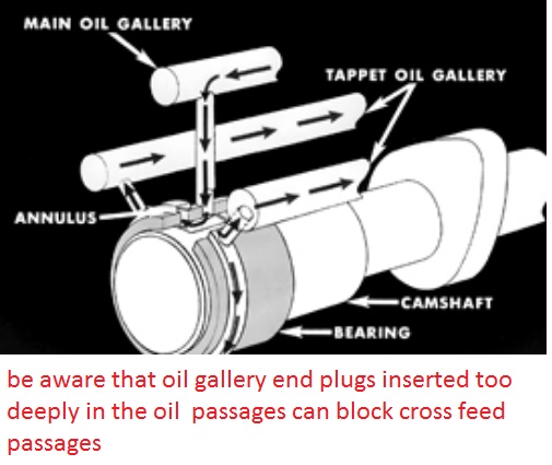
IT should be obvious that you'll need to pre-prime the blocks oil passages and adjust the rockers so oil flows from the rockers with the engine being pre-primed with a priming tool being used BEFORE trying to start any engine with a new cam to insure oil flow begins instantly on the engines start-up,you WON,T get oil to all lifters equally unless the engines crank & cam are spinning,(so during testing spin the engine slowly with a breaker bar or ratchet), because the oil passages feeding the lifters aligns differently at different lifts,your oil leak at the distributor base is normal, but the clearances and flow may be excessive, with a priming tool, some are not nearly to spec. ID measure the diam. of the oil pump primer and then measure the distributor base, Id bet the distributor base is larger and fits better, which reduces the potential for leakage.
pro-66896_w.jpg

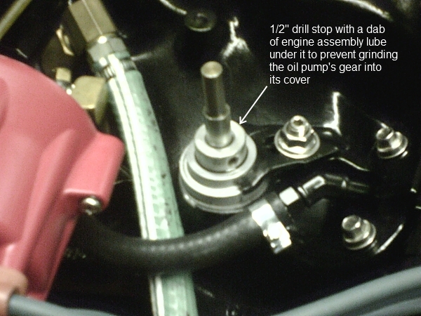
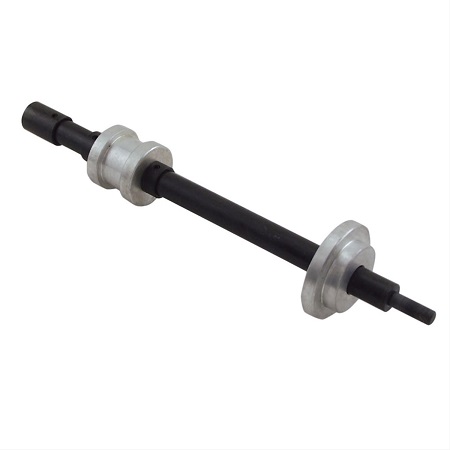
that idea of the preluber depth limiting collar , added
ON A COMMERCIAL OIL PUMP PRIMER
http://www.summitracing.com/parts/sum-901010/overview/


http://www.summitracing.com/parts/mor-62205/overview/

http://www.summitracing.com/parts/oes-27060/overview/

READ THIS LINK
https://www.crankshaftcoalition.com/wiki/Camshaft_install_tips_and_tricks

seems like a good one
preluberstop.jpg

oes-27060a.jpg

sum-901010


PrimeTool800.JPG

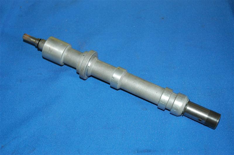
I can see a few oil pump primers, made from old distributor bodies, that might not have the necessary length to allow its use.
SBCprimer.jpg

those bottom two bands form a wall on the oil passage, some guys cut a rounded grove and install an O-RING so the upper band seals too the block, you don,t want to do that to the lower band simply because that's the oil flow source to the distributor /cam gear
20 psi is about normal for your typical 3/8 drill,max pressure is not nearly as important as checking flow, and for leaks where there should not be leaks, with an engine primer tool,Ive brazed a socket to the top of my oil pump primer and use the 1/2" drive air ratchet to drive it, it won,t heat up and burn up like a electric drill will.
don,t get alarmed if you get zero pressure or flow for a few seconds,(the oil filter and passages need to fill first) that's one reason WHY your pre-priming, to get oil flow to the bearings instantly on start up , you don,t want them running without oil flow if you can prevent it even for 20 seconds
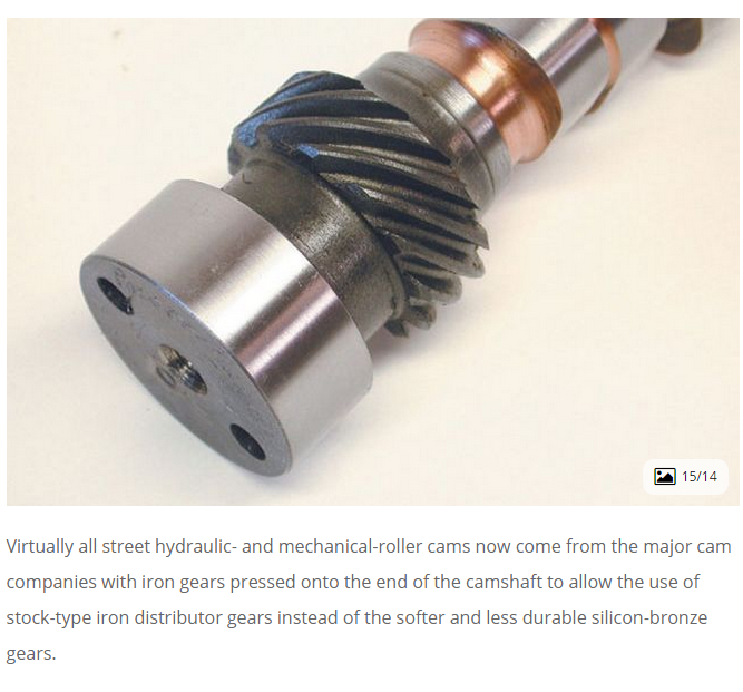
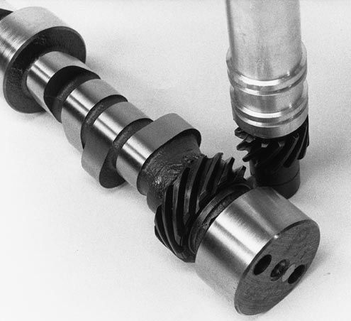
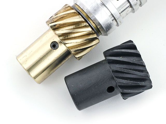
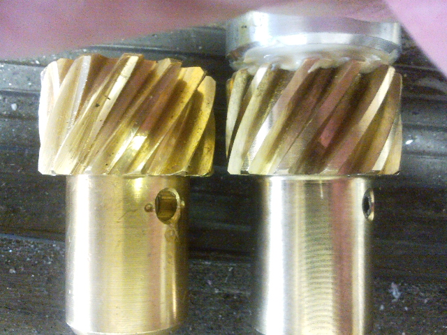
any time you change cams youll need to use a matching distributor gear, the cam manufacturer should be able to help tell you what matches, obviously checking clearances helps
and dipping the gear in moly assembly lube before it installed helps
be sure you inspect the distributor gear for excessive wear
especially if you changed from a flat tappet to a roller cam.
if your seeing the timing change a few degrees, back and forth,
slack in a work timing chain, worn distributor gear or not having the proper shim clearance on the distributor center shaft will provide slop that allows timing to vary several degrees
you might want to read thru this
http://www.drivenracingoil.com/news/dro/training-center/articles/zinc-in-motor-oil/

http://www.acdelco.com/auto-parts/v...engine-oil-supplement-assembly-lubricant.html
eos.png


»http://www.cranecams.com/?show=article&id=2

index.php
index.php

FROM MORTEC
If you are building a big block Chevy with a flat tappet cam, (solid or hydraulic lifters) be careful during the initial engine break in. It is very easy to lose a cam lobe and lifter during initial break in. This is especially true with a higher than stock lift cam and higher pressure valve springs. The increased pushrod angles found on the BBC and poor preparation can make cam lobe failure after initial fireup a distinct possibility. You can help prevent this cam lobe failure by making sure the engine is prelubed prior to intial fireup. Use a good high pressure lube on the cam lobes and lifter bottoms during assembly. If possible use a lighter pressure stock valve spring (or if using a valve spring with multiple springs, take out some of the inner springs) to intially run the engine. Then switch to the heavier pressure springs after break in. When the engine is first fired up, keep the engine rpms at 2,500 or above, don't let the engine idle for 20 minutes or longer. This keeps lots of oil splashing up on the cam lobes. Make sure the engine can be run for this time period by having enough fuel available, ignition timing set correctly, coolant available for the motor, valve lash set correctly, etc. The idea is not to crank the motor over excessively before it starts up for the first time. If your BBC flat tappet cam survives this initial break in period, it will be good to go for many miles. After the initial engine breakin, drain the oil and change the oil filter. Roller cams generally do not suffer these types of cam lobe failures during initial engine fireup.
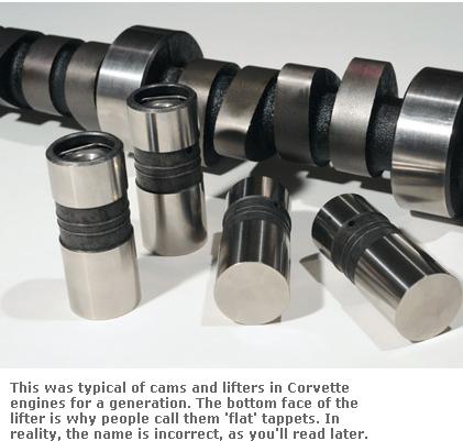
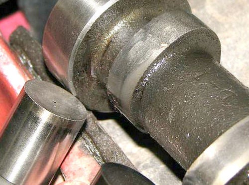
if youve adjusted the valves correctly the lifter spins at all rpm levels,but that does NOT mean it wears EVENLY at all rpm levels due to several factors if you look closely AT FLAT TAPPET CAMS youll see that the center of the cam lobe is NOT centered under the lifter and that the lifter surface is slightly angled , BOTH these factors force the lifter to spin in its bore as the lobe passes under the lifter slightly off center.

SOME of the reasons the higher rpm durring the break in phase is important is that

(1) the faster RPMs the better chances the lobe passes under the lifter floated on an oil film and the less time the oil film has to squeeze out between them

(2) the higher the RPM the greater the oil voluum and pressure the engine pumps and the more oil flow is available at the lobes

(3)the higher the rpm level the more oil is thrown from the rods onto the cam lobes

(4)the higher the rpm the greater the lifters weight and inertia tends to compensate for the springs pressure and lower the net pressure as the lifter passes over the cam lobes nose

(5) at higher rpm speed the better chance a small wedge of oil is trapped between the lifter base and lobe from the oil thrown from the lobes surface by centrifical force

(6) two differant metal surfaces scraping past each other at low speeds may tend to wear and GALL as the oil is sqeezed out but two differant hardness steel surfaces that impact each other at higher speeds covered with oil tend to work harden as they mate and will tend to be seperated by that oil

(7)as the lifter spins in its bore the contact point between the lobe and lifter base constantly changes and rotates with the lobe contact point not resisting its passage and the higher the rpms the faster the lifter rotates and the less time the lobe spends at any one point

VALVOLINE BRAND RACING OIL HAS THE HIGH ZINK/PHOSPHATE LEVELS that help prevent cam wear
ALWAYS ask questions as to the best , and most durable parts combination they have available from your cam suppliers tech department
BTW ADD E.O.S. to the oil and MOLY break-in lube to the cam
before starting the engine and prefill the filter and pre-prime the oil system before starting the engine.
I normally pour it in just before starting the engines cam break in,procedure. because I want to make sure that nothing in the oil/E.O.S. mix can settle out from sitting over a long period of time. now if your running a flat tappet cam you should have also used a moly cam lube on the lobes and be useing a mineral base oil for the break-in procedure, and youll need to do an oil and filter change after about the first 3-4 hours running time to remove that moly cam lube from the engine after its served its purpose of protecting the cams lobes and lifters at start up, aND AS THE LOBES/LIFTERS LAPPED IN. MOSTLY to prevent that moly grease and E.O.S from potentially partially clogging the filter after that mix cools down,but also because both those lubes might leave deposites in the combustion chamber ,over time that might aggravate detonation.
even G.M. suggests that E.O.S. is not a great long term oil suppliment, and that its main function is to add extra oil film strength durring new engine break in.

1052367
ENGOILSUP
EOS - Engine Assembly Prelube<BR>Specifically formulated as an engine assembly lubricant. E.O.S. provides outstanding protection against run-in wear and piston scuffing as well as run-in camshaft lobe and lifter scuffing resulting from insufficient lubrication
don,t forget a few magnets in the oil pan goes a long way towards trapping unwanted metalic dust formed from the cam and rings lapping in durring break-in that might otherwise get imbedded in your bearings or cause other problems
heres the magnets I use in every engine
https://www.summitracing.com/parts/crn-99004-1

http://www.wondermagnets.com/cgi-bin/ed ... logno=0035«

http://www.cranecams.com/?show=reasonsForFailure

http://www.babcox.com/editorial/ar/eb50232.htm

http://www.highperformancepontiac.com/t ... p_running/

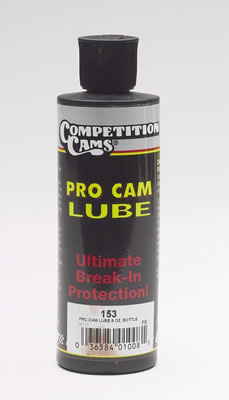
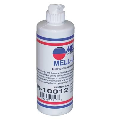
I generally mix some moly assembly lube or that melling assembly lube and MARVEL MYSTERY OIL in a container and dip solid rollers into the mix to soak for a few minutes, before installing them, its not as critical with roller lifters as with flat tappet lifters

cca-153_w.jpg


AND /OR
mel-m-10012_w.jpg


http://www.summitracing.com/parts/CCA-153/

http://www.summitracing.com/parts/MEL-M-10012

.most guys I know , that are breaking in the rings and bearings and valve train on a newly rebuilt engine, simply stick a garden hose into the radiator and let it constantly overflow onto the driveway , or they fill the radiator and seal it then place a garden hose so it runs water over the radiator outer surface,while the engine, and cam is being broken in, as its a sure way to keep the coolant temps fairly low. so no.there's no reason you can't fill the radiator with water, break in the engine then replace the coolant!, so if you do have a coolant leak your not leaking anti-freeze all over the place, until yoou get the engine tested and broken in, BTW (be sure all the gauges and sensors are correctly hooked up and working) have a timing light , distributor wrench,and fire extinguisher handy and I usually try to have a dripping wet beach towel handy as its great for quickly smothering carb fires, without the mess a fire extinguisher makes, if you get unlucky and be sure you double check the oil and trans fluid and be sure to fill and bleed the brakes and check power steering fluids also

http://www.drivenracingoil.com/news/dro/training-center/articles/zinc-in-motor-oil/

If you've ever hit a speed bump in the road thats meant to slow traffic, at several different speeds, you know theres a very noticeable relationship between the speed somethings moving and time it takes for inertia and mass of a moving object to change, direction when force is applied thru the use of a ramp changing its path of movement, and the resulting increase in shock to the components as the rate of that change over a shorter time is applied.
a speed bump is similar to a cams lobe acceleration ramp, in that it lifts the lifter/valve against spring resistance similar to your cars wheel hitting the speed bump.
a cams lobe design can rather gradually or rather suddenly impart a change in direction to the lifter in its bore and effect the speed at which the valve lifts off its seat or returns to a closed position, but that ramp design has a huge effect on the stress the valve train is subjected to as the speed of engine rotation is increased.
just like your car hitting the speed bump in the road, theres a big difference at 7 miles per hour vs 70 miles per hour, and a cam lobe that pops the valves open at idle speed of 700rpm,imparts far less stress than the same lobe spinning at 7000rpm.
naturally every choice is a compromise, lower lifts and smoother low acceleration rates make for long life and lower stress but restrict the potential area open under the valve per degree of rotation, which restricts potential breathing of the engine.
rapid ramp acceleration rates tend to increase potential hp but impart higher stress
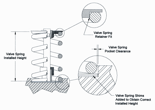
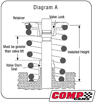
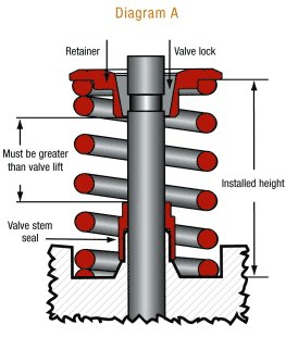
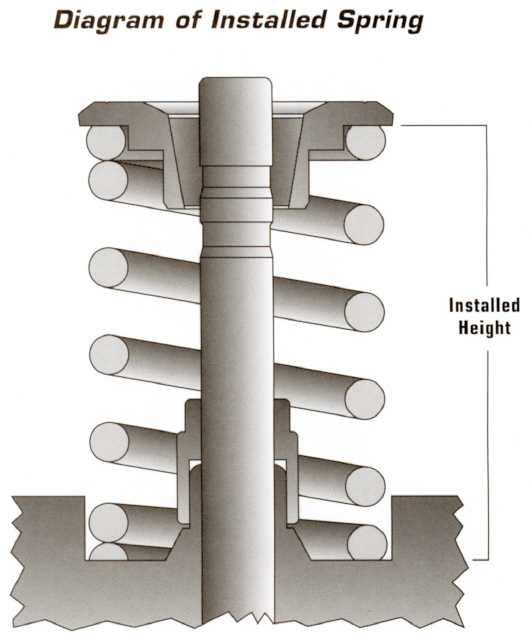
valve springs must be installed at a specific semi compressed and listed installed height,
to provide the listed load rates and clearances,
example

crane110921.jpg

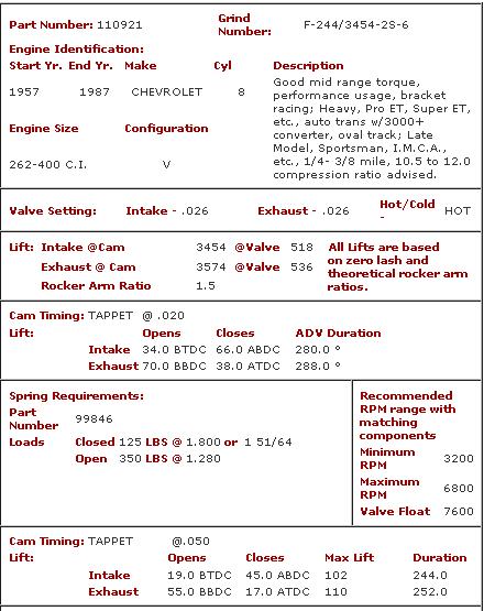
the cam you select will generally come with a suggested listed valve spring load rate and installed height,
(NOTICE THE SUGGESTED INSTALLED HEIGHT WITH THIS CAM IS 1.800"

and the loads are listed)
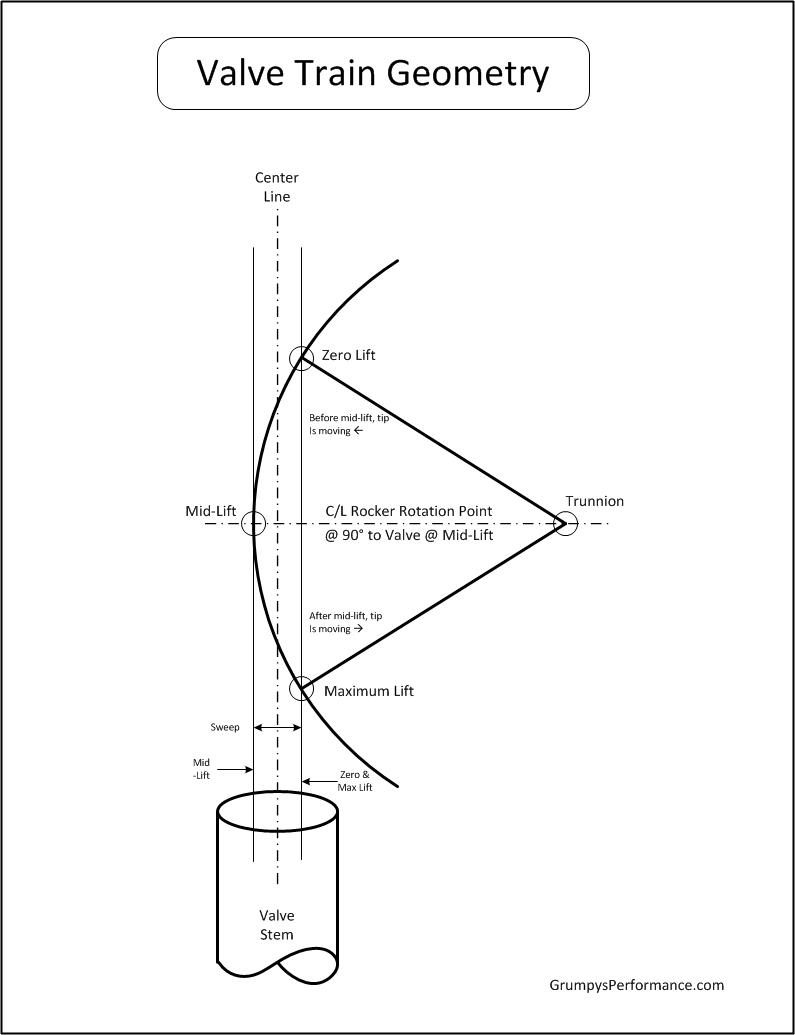
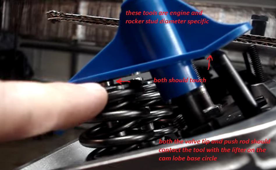
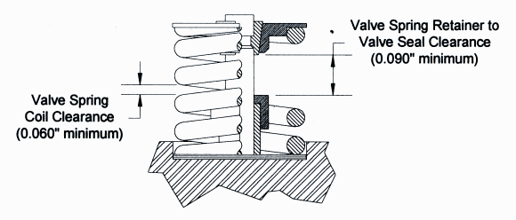
you must maintain minimum coil bind and retainer to valve seal clearance and proper push-rod and rocker geometry
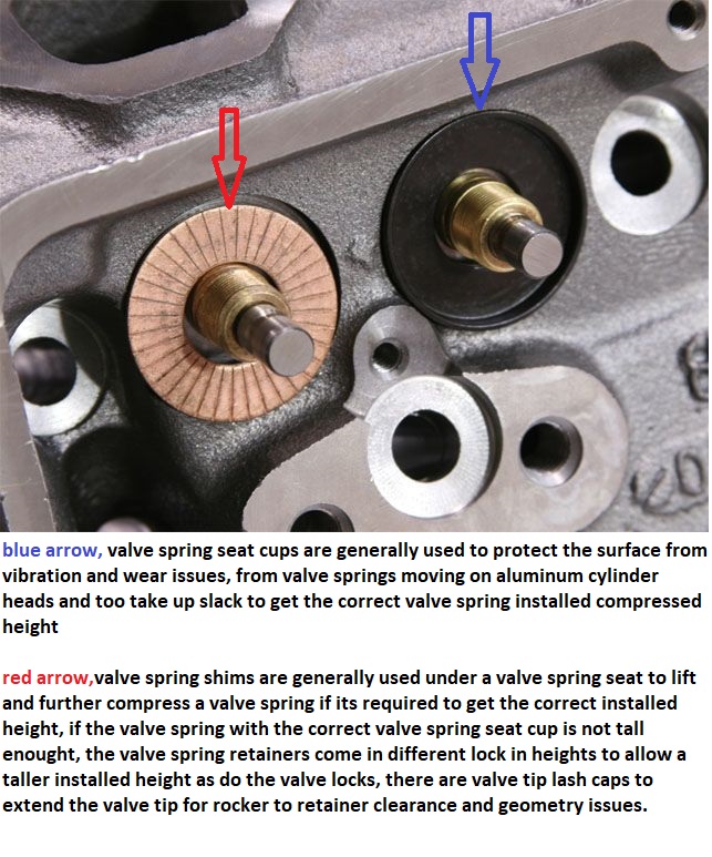
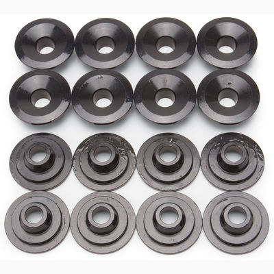
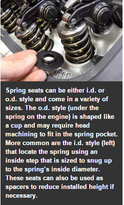
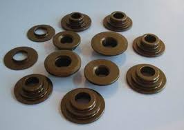
the distance between the lower edge of the valve spring retainer and the cylinder head is adjustable to achieve the desired valve spring height through the use of valve spring seat cups and shims placed under the valve spring which can be purchased to lock into a stock height, or plus or minus about .050, and valve locks that cam move the retainer (stock or aftermarket) an additional .050 either tighter or longer allowing the valve spring to expand taller, shims can be placed under the valve seat hardened cups that are almost always mandatory on aluminum head but may be optional on iron heads,(O.E.M. cast iron and lower valve spring load rates)

ValveSpringDetail.gif


clear.jpg


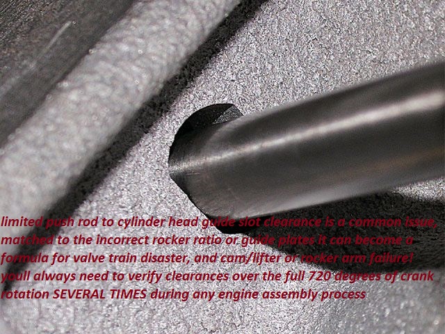
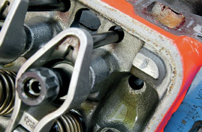
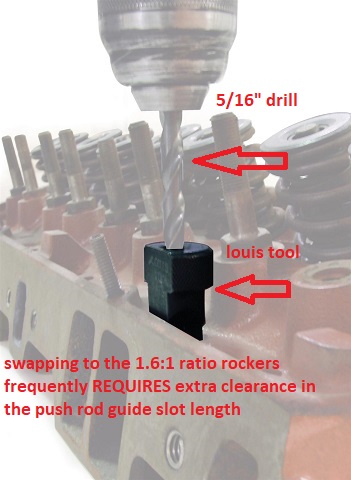
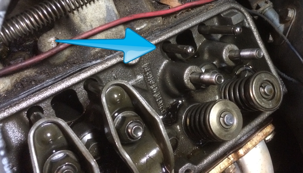
If your thinking you can swap to the 1.6:1 rockers without checking clearances carefully, ...probably not, your certainly going to need to check and verify clearances , and yeah, youll find a dozen guys that say they did it with zero problems......many could also tell you that in a few months they experienced a cam lobe /lifter or rocker failure as the push rod binding in even only part of the rockers arc, tends to cause excessive wear on the valve train, it might take some time but it will result in component failure over time if parts can,t move freely as designed.

sguide_plate.jpg

pushrodbind.jpg


youll want too use a .060 clearance too the push rod to cylinder head slot clearance CHECKED CAREFULLY OVER THE FULL ARC OF THE ROCKER TRAVEL FOR A FULL TWO ENGINE ROTATIONS
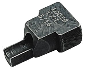
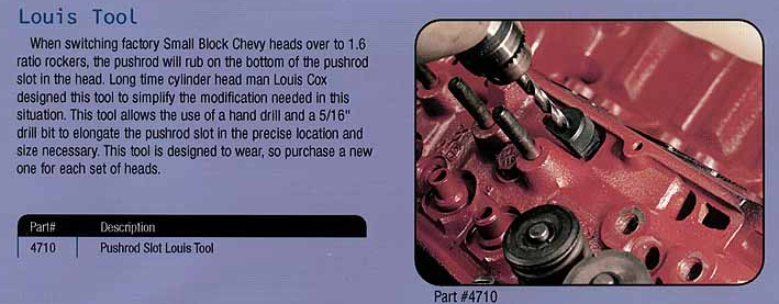
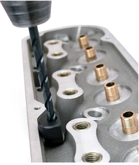
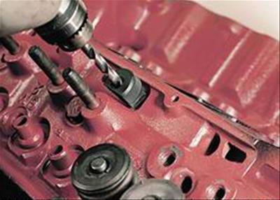
if you need a LOUIS TOOL to lengthen the slots in the cylinder head I generally lay a section of plastic wrap in the lifter gallery and be sure to place two magnets on the blocks lifter gallery wall, to hold the thin plastic wrap in place firmly, below the cylinder head while drilling to catch the metalic debris the drill will generally produce, between the plastic sheat and the magnets youll generally catch 100% of the trash the drill generates

24947101.jpg


STUD-12.jpg

louis2.png

louis1.png


pro-66485_w.jpg


btw place a magnet like this under each pushrod slot to catch the drill chips from iron heads
louist.jpg

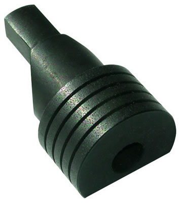
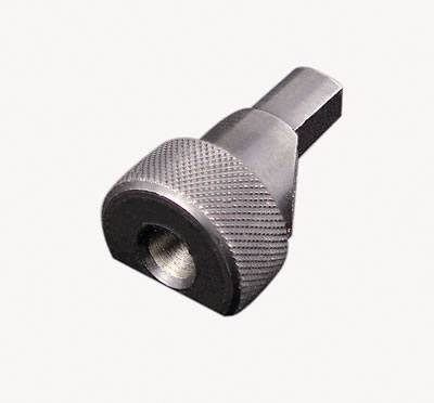
These Proform pushrod slotting tools are designed to elongate the pushrod slot in the cylinder head. They will make room for higher ratio rocker arms. Use these tools with a drill and a 5/16 in. drill bit to elongate the pushrod slot.
RockerGeometry.jpg

http://garage.grumpysperformance.co...o-rockers-and-the-pushrods-rub.198/#post-3033
http://garage.grumpysperformance.co...swap-in-1-6-1-ratio-rockers.10671/#post-46039
http://garage.grumpysperformance.co...e-train-clearances-and-problems.528/#post-664
valvespringinstalled.gif


springshima.jpg

prctool.png


retain6.jpg


bbcspring2.gif

installedheight.gif


edvalvs.jpg

valvespringseats.png

Installedsp.jpg

valvespringseatsx.png

max lift is installed height minus .060 minus coil bind
drawsdf.jpg

related info you really need to read

http://garage.grumpysperformance.co...ring-installation-questions.12833/#post-66460

http://garage.grumpysperformance.co...-loads-and-installed-height.10709/#post-46658

http://garage.grumpysperformance.co...ve-spring-iinstalled-height.12791/#post-66038

http://garage.grumpysperformance.co...train-clearances-and-problems.528/#post-57678

http://garage.grumpysperformance.com/index.php?threads/valve-springs.9613/#post-50556

Isky claims that the Comp XE cams violate the 47.5% rule.
The 47.5% rule applies to flat tappet cams for SBCs with 1.5 rockers but the concept is still the same for other configurations where the designs are "on the edge" or "over the edge" for lobe intensity.
For 1.5 ratio SBCs, the duration at .50 must exceed 47.5% of the total valve lift or your asking valve train problems.
For example, take a Comp Cams Magnum 280H, with 230 duration and, 480 lift...230/.480 = 47.9% which exceeds 47.5% therefore would not pose a threat to components.
We do not regularly hear about the older, safer HE and Magnum designs rounding off lobes anywhere near as often as the XE cam designs.
Unfortunately, some of the Comp Cams XE dual pattern lobes break this 47.5% rule on the intake side so they are likely to be problematic.
The design has "steeper" ramps that are too quick for durability and reliability according to most other cam manufacturers.
They will wipe lobes in a heart beat especially if you have not followed the proper break-in procedure.
Other designs are more forgiving during break-in and less likely to fail.
 
Last edited by a moderator:
BBC engines have developed a reputation for eating cam lobes because most guys either don,t break the cam in correctly or are not willing to make the mods necessary to supply the extra oil flow that prevents it from HAPPENING with the INCREASED Pressures aftermarket cams with their higher lift, duration, ETC. and springs produce
first ID strongly suggest a high volume oil pump and a windage screen with a baffled high volume pan,
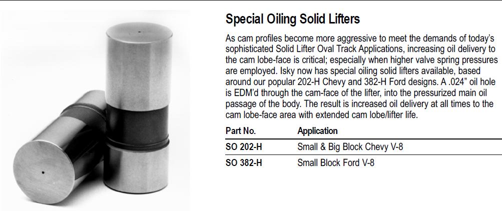
use the solids with the extra oil bleed hole that feeds oil to the lifter/cam lobe contact area
http://www.crower.com/misc/m_cat.shtml (pr107)
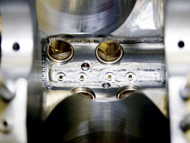
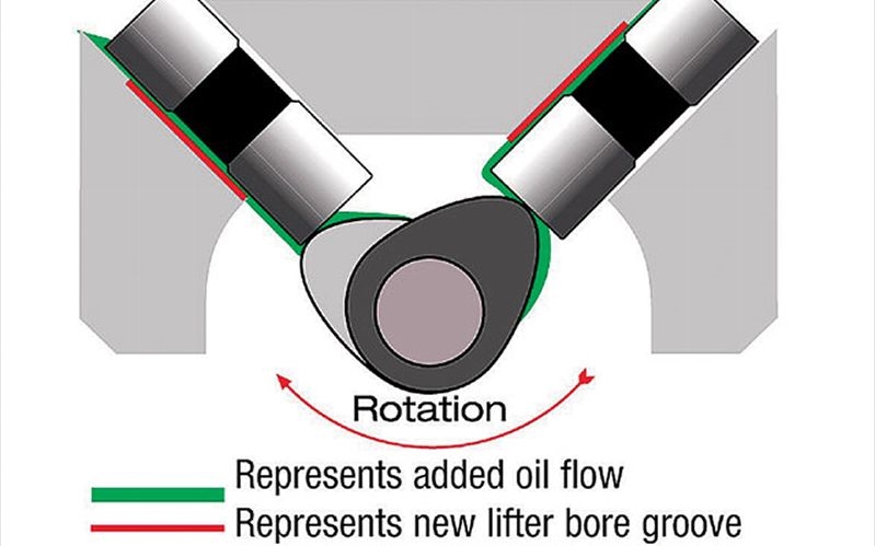
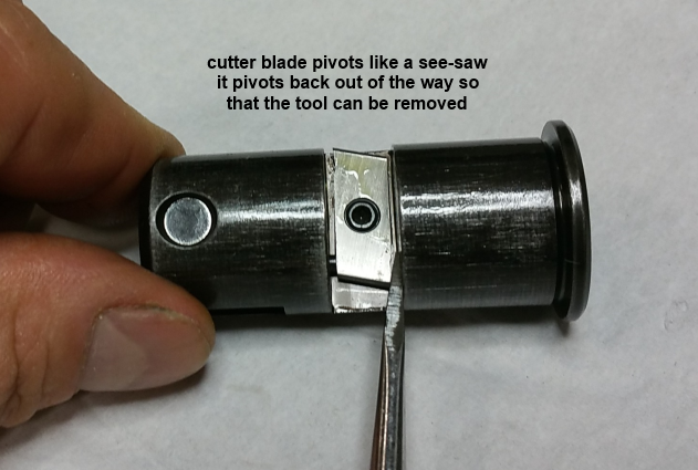
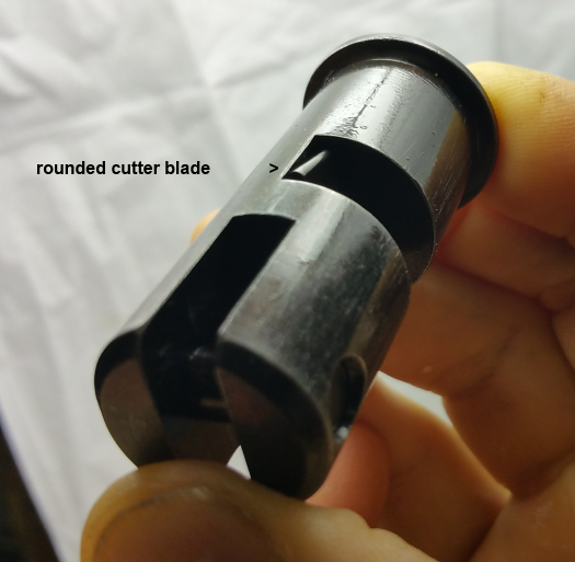
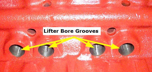
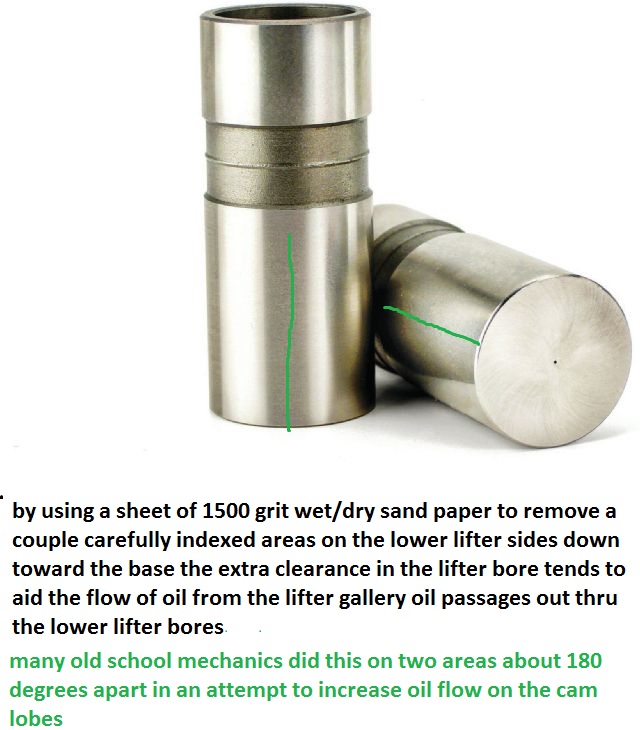
both crower and comp cams sell them, but they are fairly expensive compared to standard solid lifters, I tend to use them when I can get them but it might be overkill on the oil flow to some extent because I use this tool too put a slight groove in the lifter bores that constantly sprays oil onto the cam lobe at a point just before it rolls under the lifter base

http://www.compcams.com/catalog/335.html
\it only takes a few seconds running a new engine for an improperly installed cam , lifters and valve train, during the break-in process to generate teaspoons of metallic trash that ,once in the engine oil flow ,rapidly destroys bearings if the clearances ,spring load rates or valve train geometry is wrong
CROWER and COMP and HOWARD CAMS now sell solid flat tappet lifters with EDM drilled holes to do something similar too force oil out of the lifter base directly on the cam lobes.
groovelc1.jpg

COMP SELLS A TOOL TO GROOVE LIFTER BORES
335.jpg

groovelc2.png
groovelc3.png

groovelc4.png

groovelc5.png

groovelc6.png

groovelc7.png

groovelc8.jpg

When I use the lifter bore grooves, I have always suggested a big block style oil pump be used as those grooves allow part of the oil flow to take a short cut out the lower lifter bore to keep the cam lobe/lifter contact area well lubricated, but that also means LESS oil reaching the bearings and rockers than you would have with the identical set-up without the lifter bore groove thus adding extra oil flow volume with the larger 12 tooth oil pump makes up for the lost volume

sbcvsbbcgears.jpg


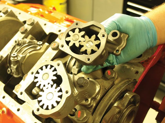
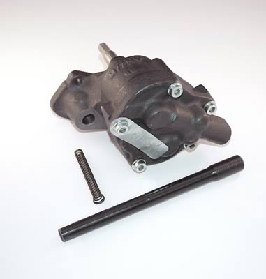
10552 high flow SBC 4 BOLT COVER OIL PUMP
http://www.summitracing.com/parts/mel-10552

High volume performance oil pump.
10% increase in volume over stock oil pump.
The 10552 is manufactured with the drive and idler shafts extended to allow for additional support in the cover eliminating dynamic shaft deflection at increased RPM levels.
The cover is doweled to the pump housing to assure alignment of the shaft bores.
Screw in plug retains relief valve spring instead of pin.
Relief hole in cover uses screw in plug instead of pressed cup plug.
All bolts are self locking socket heads, with the wrench supplied.
The housing and cover are CNC machined and phosphate coated.
Includes intermediate shaft with steel guide. Uses both 3/4” bolt on or press in screen.
The lower pressure spring is included to reduce pressure if desired.
Patent No. 5,810,571.
mel-10778c_w.jpg

10778C (Anti-Cavitation)
(NOTICE ITS A 5 BOLT BIG BLOCK HIGH VOLUME OIL PUMP WITH A 3/4" pickup}
http://www.summitracing.com/parts/mel-10778
High volume performance upgrade for the 10770.
Increase in volume of 25% over stock oil pump.
The same as the 10778 except with the addition of grooves machined in the housing and cover. The grooves reduce cavitation effects in high RPM applications.
Using this oil pump will reduce pressure at idle.
Includes intermediate shaft with steel guide.
Uses 3/4” press in screen.
Racing applications only.
Patent No. 5,810,571


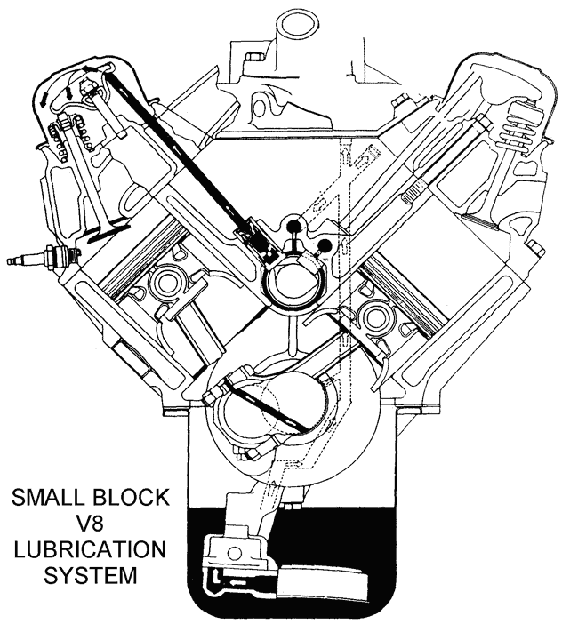
A-ENGINE-OIL-02-small-block-v8-lub-sys.gif

265_oil-2.jpg


sbcoilh3.jpg


sbcoilh4.jpg

sbcoilh5a.jpg

sbcoilh6a.jpg

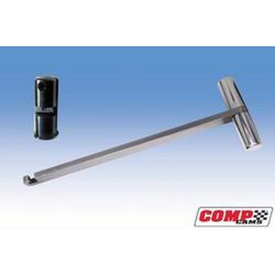
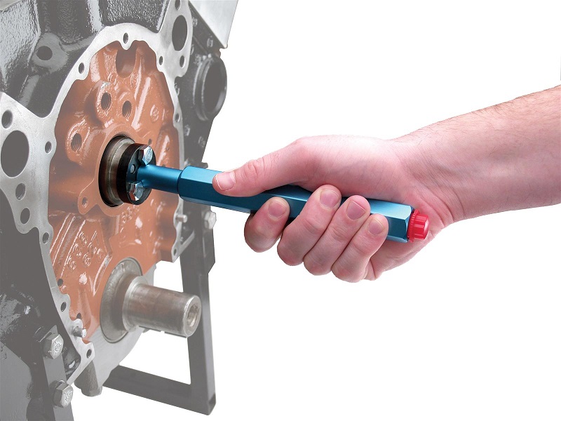
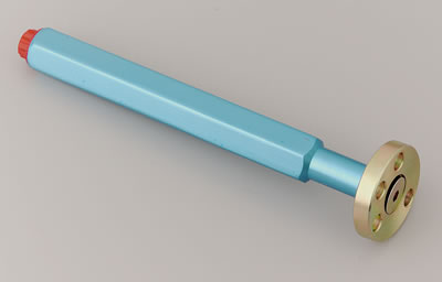
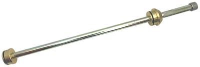
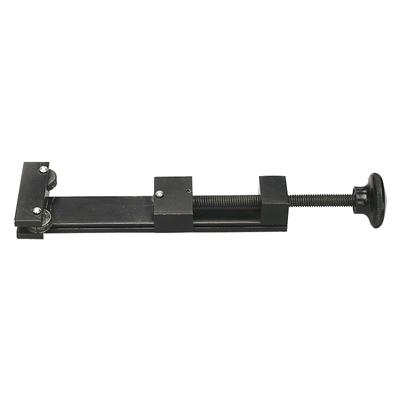
use of a camshaft install handle generally reduces the chances of damaged cam bearings
CCA-4919_xla.jpg

cca-4919_w.jpg

frontgroove.JPG


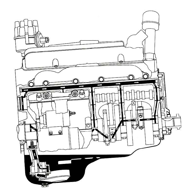
SBOilSystem2.jpg

if you've adjusted the valves correctly the lifter spins at all rpm levels,but that does NOT mean it wears EVENLY at all rpm levels due to several factors if you look closely AT FLAT TAPPET CAMS , youll see that the center of the cam lobe is NOT centered under the lifter and that the lifter surface is slightly angled , BOTH these factors force the lifter to spin in its bore as the lobe passes under the lifter slightly off center.
If your engine does not run as well as expected or starts back firing, missing etc shortly after a new cams been installed, your valves might be adjusted too tight , the ignition advance curve may not be correct,
and as previously mention,
you may need a bit more accelerator pump volume from what you've stated
check the carb float levels and look for vacuum leaks loose hoses and loose electrical connectors and check firing order carefully.
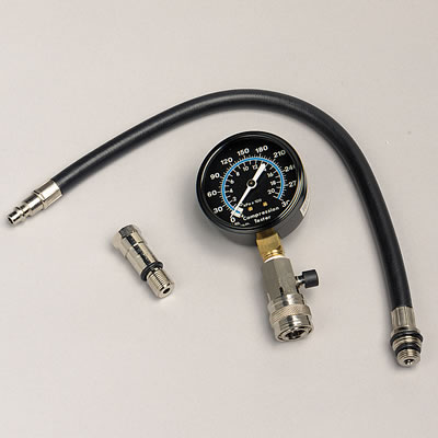
do a compression test
sun-cp7827_w.jpg

you might have over tightened a valve and bent it on a piston
check the cam lobe lift with a dial indicator
dialinc2.jpg

Slide-81.jpg


pro-66830_cp.jpg


checklifter3.jpg

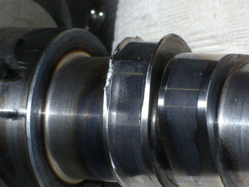
you might have had a cam lobe fail.

worn1.jpg

worn2.jpg

worn3.jpg


read this link

http://www.engineprofessional.com/articles/EPQ215_18-38.pdf


http://garage.grumpysperformance.co...ng-piston-to-valve-clearances.399/#post-74297

http://garage.grumpysperformance.co...rect-custom-length-pushrods.14241/#post-72346

http://garage.grumpysperformance.com/index.php?threads/acceptable-lobe-variation.13654/#post-70348


http://garage.grumpysperformance.co...iepts-on-each-car-maintinance.1467/#post-3297

SOME of the reasons the higher rpm during the break in phase is important is that

(1) the faster RPMs the better chances the lobe passes under the lifter floated on an oil film and the less time the oil film has to squeeze out between them

(2) the higher the RPM the greater the oil volume and pressure the engine pumps and the more oil flow is available at the lobes

(3)the higher the rpm level the more oil is thrown from the rods onto the cam lobes

(4)the higher the rpm the greater the lifters weight and inertia tends to compensate for the springs pressure and lower the net pressure as the lifter passes over the cam lobes nose

(5) at higher rpm speed the better chance a small wedge of oil is trapped between the lifter base and lobe from the oil thrown from the lobes surface by centrifugal force

(6) two different metal surfaces scraping past each other at low speeds may tend to wear and GALL as the oil is squeezed out but two different hardness steel surfaces that impact each other at higher speeds covered with oil tend to work harden as they mate and will tend to be separated by that oil

(7)as the lifter spins in its bore the contact point between the lobe and lifter base constantly changes and rotates with the lobe contact point not resisting its passage and the higher the rpms the faster the lifter rotates and the less time the lobe spends at any one point

BTW ADD E.O.S. to the oil and MOLY break-in lube to the cam
before starting the engine and pre-fill the filter and pre-prime the oil system before starting the engine.
I normally pour it in just before starting the engines cam break in,procedure. because I want to make sure that nothing in the oil/E.O.S. mix can settle out from sitting over a long period of time. now if your running a flat tappet cam you should have also used a moly cam lube on the lobes and be using a mineral base oil for the break-in procedure, and you'll need to do an oil and filter change after about the first 3-4 hours running time to remove that moly cam lube from the engine after its served its purpose of protecting the cams lobes and lifters at start up, and AS THE LOBES/LIFTERS LAPPED IN. MOSTLY to prevent that moly grease and E.O.S from potentially partially clogging the filter after that mix cools down,but also because both those lubes might leave deposits in the combustion chamber ,over time that might aggravate detonation.
even G.M. suggests that E.O.S. is not a great long term oil supplement, and that its main function is to add extra oil film strength during new engine break in.

Is coil bind height and open height the same thing? The springs I'm wanting to go with have an installed height of 1.940 and open height of 1.250. With .600 exhaust lift, does that give me .090 before coil bind?

If your installing your own can bearings you want to clean the oil passages out first carefully, pay attention during the process and if if the cam bearing your using seams to be loose spend the $20 for a new set , of cam bearings rather than chance it coming loose.
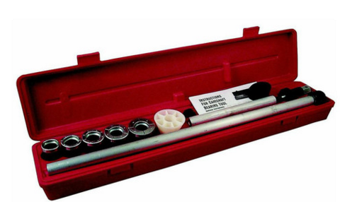
one more reason to buy a cam bearing install tool.


http://garage.grumpysperformance.com/index.php?threads/cam-bearing-install-tools-install-info.1479/
AAF-ALL96470.jpg
usual cost of about $32
http://www.summitracing.com/parts/AAF-A ... /?rtype=10

the cheaper tool pictured above works fine, but I never saw one for sale decades ago
http://www.summitracing.com/parts/AAF-ALL96470/?rtype=10
camtooll.png

I bought a used tool,
( ONLY USED ONCE IF YOU BELIEVE THE SELLER) at a swap meet 40 years ago that looked similar to this for $70

http://www.cpooutlets.com/lisle-180...ap=lisn18000&gclid=CIum95iqhcsCFQUIaQodk3YDfw

http://www.lislecorp.com/uploads/instructions/18000_WebInstr_CC56DD9726DB5.pdf
drawsdf.jpg


installed height is open height, the springs set up to provide a minimal resistance before it can be compressed further, the cam card below may help
crane110921.jpg

notice the listed info
cranesp1.png

A BIT OF QUICK RESEARCH


Crane Cams#271-99846-16
Single Valve Springs
Outside Diameter: 1.255"
Inside Diameter: .870
Seat Pressure: 125 LBS @ 1.800"
Open Pressure: 383 LBS @ 1.200
Coil Bind: 1.100"
Rate (LBS/IN.): 428
Max Lift: .640
Set of 16

http://www.jegs.com/i/Crane-Cams/271/99846-16/10002/-1


notice the coil bind height PLUS, approximately the .090 is the listed max lift, and the max lift on the cam or open height is a bit less.
engines require clearances to work correctly and with valve springs having a bit of extra clearance helps durability, this is generally one reason WHY cams are sold with a strongly suggested set of load rates and clearances so they can operate under know and expected stress levels they were designed for
high spring loads, lack of lube, low oil flow, and the wrong clearances , don,t play well with roller or flat tappet cams over long term use
wornrollercamlobe1c.jpg


crn-99004.jpg
crn-99004.jpg
crn-99004.jpg
crn-99004.jpg
crn-99004.jpg
crn-99004.jpg
crn-99004.jpg
crn-99004.jpg

cambreakin.jpg

worn1.jpg

worn2.jpg

worn3.jpg

worn4.jpg

worn5.jpg

worn6.jpg

worn7.jpg

worn8.jpg


1052367
ENGOILSUP
EOS - Engine Assembly Prelube<BR>Specifically formulated as an engine assembly lubricant. E.O.S. provides outstanding protection against run-in wear and piston scuffing as well as run-in camshaft lobe and lifter scuffing resulting from insufficient lubrication
1052367.jpg

don,t forget a few magnets in the oil pan goes a long way towards trapping unwanted metalic dust formed from the cam and rings lapping in durring break-in that might otherwise get imbedded in your bearings or cause other problems
heres the magnets I use in every engine

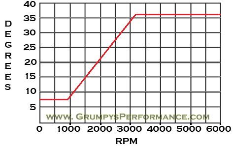
naturally you need to verify the oil and coolant levels are correct,and set your valve preload or lash a bit loose, then since your not going to run the engine at low rpm you install timing tape on the damper and verify TDC on the damper and timing tab match TDC on the engine, then you set the timing at 3200rpm at about 34 degrees btdc during the break in, during the first few seconds it runs
remember it will tend to run a bit hot if the fuel/air ratio gets lean(VACUUM LEAKS)
or if the timings RETARDED, and while the rings and valve train break_in (LAP IN)so a moly cam lube and a quart of marvel mystery oil and some E.O.S. or crower lube helps reduce heat.
http://www.crower.com/misc/product/dl/ZDDP_clr.pdf
zddplus.jpg


http://www.summitracing.com/parts/CRO-86092/

standard procedure during cam break-in is to place a garden hose flowing water thru the radiator fins, as the hoses water flow absorbs heat far more effectively from the radiator surface, it helps to have a large shop fan blowing air also


sum-161588.jpg

mrg-1591.jpg


http://www.summitracing.com/parts/MRG-4599/?image=large

mrg-4599_w.jpg


viewtopic.php?f=50&t=723

http://www.summitracing.com/parts/MRG-4598/

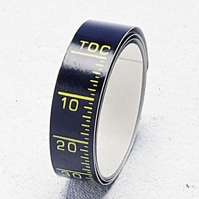
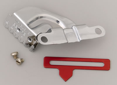
the use of timing tape on the damper is a huge help and yeah, the glue on the tape tends to get loose so use some contact cement sparingly, the contact cement works, but a simple spray coat of a clear lacquer spray paint sprayed over the tape and allowed to dry locks it on the damper fairly well also, or you can spend just a bit more, and buy a damper cover, and adjustable timing tab, just remember to verify TDC
Id especially change the oil, and filter, and slap a big magnet on the base of the oil filter
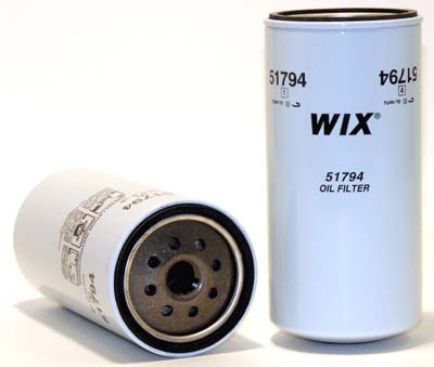
51794.jpg

clip on a decent magnet to the base of a long oil filter helps it trap metalic trash more effectively, and while $29 may sound high its good extra insurance that potentially reduces the chances of metalic debis from getting to the bearings and valve train.
consider the cost of bearing replacement?
filtmag.png

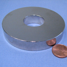
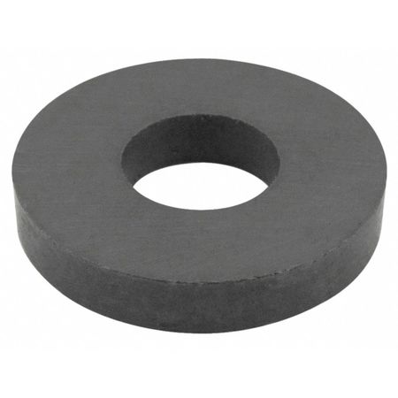
http://www.magnet4sale.com/n42-3od-x-1id-x-1-2-neodymium-rare-earth-ring-magnet/

change the oil, and filter, and slap a big magnet on the base of the oil filter
http://www.magnet4sale.com/n42-3od-x-1id-x-1-2-neodymium-rare-earth-ring-magnet/
3ringmag.jpg


and a couple high heat tolerant magnets,
viewtopic.php?f=44&t=799&p=2048&hilit=break+in+moly#p2048

http://www.wondermagnets.com/cgi-bin/edatcat/WMSstore.pl?user_action=detail&catalogno=0035

http://www.cranecams.com/?show=reasonsForFailure
 
Last edited by a moderator:
Cam Failures: Some thoughts on cam and lifter wear
By Charles Reichard (FROM CAMCRAFT SITE)

http://www.camcraft-cams.com/index.php? ... m-failures

http://garage.grumpysperformance.com/index.php?threads/viscosity-centistoke.15612/

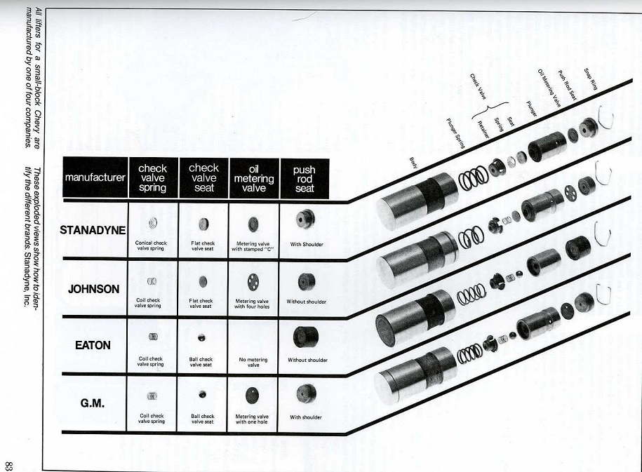
There has been a lot of discussion regarding the increase in flat tappet cam failure the last few years. Much finger pointing goes toward our only domestic flat lifter supplier, Stanadyne. We started using Stanadyne lifters about a year and a half before the lifter shortage hit. We had NO increase in lifter failures when we changed over. The lifters look different so there was no old stock involved or anything like that. One order we got Eaton’s and the next Stanadyne’s. The primary visible difference was the Eaton lifters were Parkerized on the bottom and the Stanadynes were not. The metering system is also different. The Parkerizing is a protective coating used on cams and sometimes lifters that disappears a few seconds after startup. This coating is deposited in an acid solution that slightly degrades the finish on the lifter foot. According to Stanadyne, they have made no change in their lifter manufacturing procedures or materials.

Chrysler Corp. stopped Parkerizing all their cams many years ago when they discovered this degradation of the surface finish actually contributed to cam failures in their 2.2L OHC engines.

Almost all domestic camshaft castings come from the CWC foundry in Muskegon, MI. The heat-treating is done at the foundry. While there can be several different casting patterns used for each engine, the material is usually identical except for the P55 castings. The heat-treating is also identical. There have been no changes at CWC or at their customers supplying semi-finished castings to the performance market other than some increased automation. About the only significant difference in the castings is the lobe width, with wider lobes offering greater load carrying ability.

Why then are we seeing an increase in cam failure? There are several contributing factors. The first and likely primary factor is the lack of zinc additive in most of today’s oils. As I understand it, all oils for highway use have NO ZINC. Zinc has, for many years, been one of the primary antiwear additives in motor oils. Due to factors involving contamination of catalytic converters, zinc has been outlawed in motor oils for highway use. There has been a decrease in zinc content for several years but as of January 1, 2004, it is eliminated in all oils for highway use. If an oil contains zinc, it must be labeled “ for off road use only” or “Not for highway use”. Diesel oils may be an exception. Several of our racing customers have switched to 15W40 diesel oil with good results. (6/1/2007 Word is out that zinc has now been removed or substantially reduced in the diesel oils)

A very useful web site with lots of oil related information is www.bobistheoilguy.com. I had only a few minutes to peruse the site but it had lots of very useful information. Check it out!

Another significant factor is the increased use of synthetic oil. While some synthetic oil works ok with flat tappet cams, many do not. Never break in a fresh engine with synthetic oil. There are no cam grinders that I know of that recommend the use of any synthetic oil with flat tappet cams. The use of synthetics is primarily needed in very high temperature or low temperature applications. If you properly control the oil temperature you have less need for synthetics. Several of our customers add 2 quarts of conventional oil to their synthetic oil with good results.

An excellent additive with high zinc content is General Motors EOS. I haven’t seen a new bottle yet but I have heard that the label has been changed from engine oil supplement to engine assembly lubricant so it won’t be used as an oil additive regularly. I have heard on good authority that EOS is not compatible with Mobile 1 synthetic oil. That doesn’t necessarily mean anything as to compatibility with other synthetic oils. Other companies such as Prolong, have similar additives.

Another significant factor continues to be lack of proper break in procedure. While many engine builders remove the inner spring for break in, often this is not enough. Higher rocker ratios popular today mean increased spring pressures and very significantly higher stress across the nose of the lobe. Often the open pressure with outer springs only is still too high for proper break in with these higher ratio rockers. We like to see open pressures less than 275 lbs for break in.

The best break in involves 1.2 or 1.3 rockers with the inner springs removed. After 30 minutes at 1500-2500 rpm install the inner springs and run with the break in rockers. Next run with 1.5 rockers, and then with the final rocker ratio to be used. This is time consuming to say the least but not nearly as time consuming as disassembling the engine to clean out several ground up lobes and buying gaskets, rings and bearings at the least. Our customers that follow this procedure have far fewer cam failures than the ones who don’t.

It is very important that the engine fire immediately. Excessive cranking will wipe the assembly lube from the cam and lifters. Be sure the timing is set and the carb full of fuel. The engine should run between 1500 and 2500 rpm for about 30 minutes. Vary the speed a bit during the break in.

Many customers like to point the finger to soft lobes or defective castings. Having a soft lobe is as likely as putting your hand in a bucket of water and having 1 finger come out dry. A single soft casting is unlikely as well. We buy Small Block Chevy castings 65 to 150 at a time. If there is a defective batch of castings then we are going to see a huge number of failures in the space of a few days from several different customers. If you have 1 or 2 worn lobes and the rest look fine then there is nothing wrong with the cam. About the only issue that the cam grinder controls is the taper on the lobe. Even this can vary a bit with no ill consequences. Another less obvious factor is the lobe lift for a given duration and rocker ratio. A lobe design that has too much lift for the duration will have a sharper nose radius. This has a detrimental effect on wear and is greatly aggravated by high rocker ratios. Sometimes it is advantageous to use a little less lobe lift to still take advantage of the faster valve opening offered by the higher rocker ratio.

Then there are the failures that we can only file under “stuff happens”. We see strange things, like obvious indications that the lifter was not rotating for a short time but with no major failure. This is often indicated by a thin line the width of the lobe on the bottom of the lifter. It can be seen and felt easily. We have seen this several times in cams with 6 or more races and significant dyno time that have virtually no cam wear. After replacing the lifters there were no further problems. Obviously the lifter had started rotating again at some point. Lifters frequently don’t rotate much if at all at idle or low rpm. Some engine builders cut a slot on the inner side of an old valve cover so they can observe pushrod rotation at higher engine speed without getting an oil bath.

It is critical to make sure race engines do not idle at low rpm for prolonged periods. The cam and lifters depend largely on splash lubrication for survival and there isn’t much splash going on at idle. Also the lifters will rotate less at low rpm.

Another less obvious thing is using a heavy cam lube on the sides of the lifter. This can temporally inhibit lifter rotation. Use only light motor oil on the lifter body and the heavy lube on the bottom of the lifter and the lobe. Don’t forget to lube the distributor drive gear and fuel pump lobe as well. Be sure to check the actual lifter clearance in the lifter bore

I am a great believer in preheating the oil and water in any performance engine. It can be difficult to heat the oil for some but anyone can put hot water in the radiator for initial startup. A small torpedo heater can be used to warm up the oil if you don’t want to spring for a little heat pad that sticks on the oil pan. Some people use a heat lamp near the pan for an hour or so. It is also important to initially break in the engine with lighter oil so it can get circulating more quickly. We don’t have to worry about heavy loads or high temperatures during break in.

Sometimes, despite your best efforts, you still wipe out a cam occasionally. If the proper procedures were not followed then you know why. Often people say, “I never did all that stuff before and never had a problem. Why should I do it now? Today’s cam profiles are very different from those of a decade ago. They impose a higher load more quickly than older designs due to higher acceleration rates and frequently have higher lift. Also valve springs are significantly improved and often have higher open pressure. If you don’t follow proper break in procedure then you will experience cam failure sooner or later.

Another frequently overlooked item is truing the lifter bores. Lifter bores are frequently not located properly even in brand new blocks. Even if they are not tilted fore and aft, which would create excessive wear, they can be mislocated axially which would change the cam timing on those cylinders causing a loss in power. Even brand new blocks should get lifter bores trued, bushed and precision bored and honed. The lifter bore clearance is different for different types and diameter lifters. Check with the lifter manufacturer for proper clearance.

When you use 1.2 or 1.3 rockers for break in, be sure to trial fit them before final assembly of the head. They frequently require elongation of the rocker arm slot or hole away from the rocker stud. This is the opposite of the work required for high ratio rockers that require machining the slot toward the stud.

Following all the proper procedures for cam and lifter break in doesn’t necessarily guarantee you will never wipe out a cam but it increases your chances for success 10 fold. We have several NASCAR Late Model Stock customers that get 2 or even 3 seasons out of a cam and lifters. They typically race 75-150 laps every week + practice and qualifying. That represents a lot of laps.

Everyone should be evaluating their break in procedures. You can spend a little extra time initially or much more time and money doing it over later. Be sure to evaluate your oil and be certain it contains zinc. It is a good idea to use an oil additive high in zinc content. Flat tappet cams can provide long life and very good power output if they are properly installed and broken in carefully.
 
Last edited by a moderator:
youll be best served following the manufacturers suggested clearances or (LASH). if your running a solid lifter cam, if they suggest .016 than set them at that, its not critical that they are EXACTLY .016-018,should be fine, but get it as close as you reasonably can.
generally set them on a warm engine , but be 100% sure the valve train geometry and clearances are correct and oil flows from each individual pushrod to each rocker,
heres a few useful links

https://www.summitracing.com/parts/crn-99004-1

http://www.wallaceracing.com/valvelash.htm

http://www.cranecams.com/?show=faq&id=4

http://www.chevyhiperformance.com/techa ... index.html

http://www.centuryperformance.com/adjus ... g-149.html

http://www.small-block-chevy.com/cb_5.htm

http://guarddogmolylubricants.com/about-moly.shtml

http://www.rosemill.com/html/WhatTheHeckIsMoly.pdf

http://garage.grumpysperformance.co...iepts-on-each-car-maintinance.1467/#post-3297

1/4 turn in from the point the lifter just stops clicking at idle has worked the best over the years for me
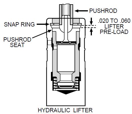
Ive always found the final adjusting of HYDRAULIC LIFTERS is best done at idle, with the engine up to operating temps., as it allows for all the variables like heat expansion and lifter seat movement as the oil pressure lifts the push rod seat) of course a tall valve cover roughly similar to this mod helps reduce the potential for a mess

https://www.theengineblock.com/battle-of-the-lifters-flat-tappet-roller-solid-hydraulic/

http://www.superchevy.com/how-to/en...-differences-between-flat-tappet-roller-cams/

https://www.hotrod.com/articles/flat-vs-roller-tappet-better/

https://www.enginebuildermag.com/2006/07/vizards-view-avoiding-flat-tappet-cam-and-lifter-failure/

http://www.engineprofessional.com/articles/EPQ317_62-66.pdf

https://www.onallcylinders.com/2017/09/22/making-modern-flat-tappet-camshafts-lifters/
DSC01822_800_x_600_.jpg
 
Last edited by a moderator:
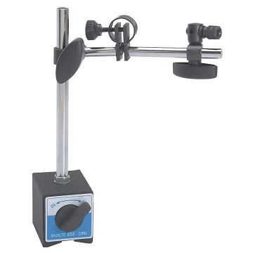
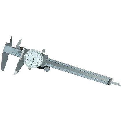
well theres several ways, use of a magnetic base with a dial indicator will allow you to compare each rocker as it moves thru it arc. the intake rockers and then the exhaust lobe readings should all match within a few thousands of an inch
yes the additives in the the quart of MMO you can add to your crank case oil, do a good job of breaking up and holding in suspension oil sludge and transporting it to the oil filter
marvel.jpg

read thru these links


http://www.harborfreight.com/cpi/ctaf/d ... umber=5646

http://www.harborfreight.com/cpi/ctaf/d ... mber=93295

visual inspection on a BIG BLOCK is easier than on a sbc, but heres a tool that will help at times

viewtopic.php?f=62&t=881&p=1389&hilit=leakdown#p1389

viewtopic.php?f=27&t=1514

don,t forget as many guys do, that swapping to a higher ratio rocker changes the push-rod rocker geometry,and clearances, and may require a different length push-rods.

pic19.jpg

I buy most of my replacement valve springs from these guys
http://www.racingsprings.com/
(866) 799-9417
http://www.racingsprings.com/Staff
heres their ph#
Toll Free (866) 799-9417
I always just order the springs retainers valve locks and spring seats as a package deal (NOT CHEAP BUT EVERYTHING WORKS AND FITS) then you just need shims under the valve spring seats occasionally to get the correct installed height

http://www.summitracing.com/parts/sum-900013/overview/

http://www.summitracing.com/parts/sum-900012/overview/


SUM-900012_xla.jpg

btvalve.png


springt1.jpg

springt2.jpg

springt3.jpg

springt4.jpg

springt5.jpg

springt6.jpg

springt7.jpg


I watched that video, and my first thought was......
hey I'm a tool junky, so what will this new tool do for me?
great, she has a rocker and she is depressing a valve spring and it reads 100 psi?
NOW what?

what does that tell her?
how far was the valve spring depressed too read 100 psi? if the valve retainer moved with that tool on the rocker at 100 psi, then thats a ROUGH guide to finding valve seat pressure
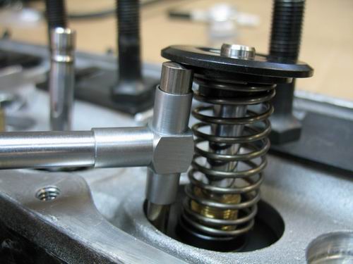
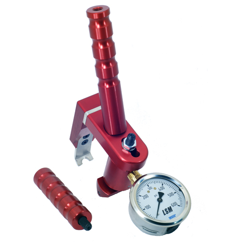
what she has there is a tool that might easily be used to locate a cracked or broken valve spring,
but not much else in the way of useful data, could be found with it, so what good is it? you could most likely do that the old way with a quick push down on each valve spring retainer with an educated/ experienced thumb!
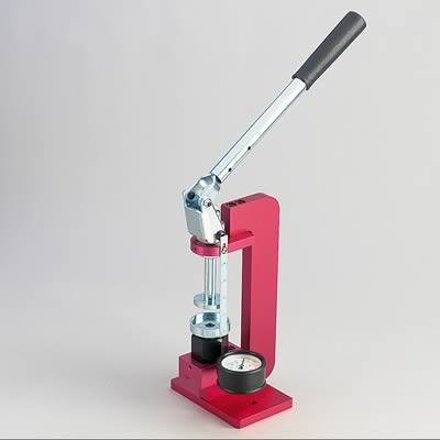
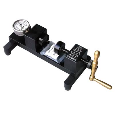
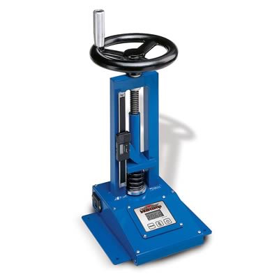
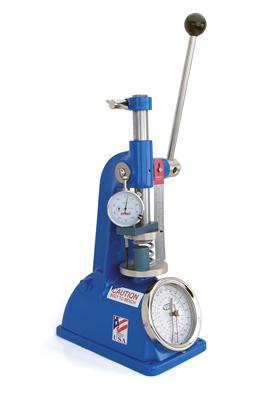
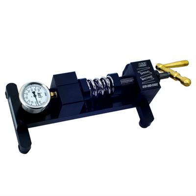
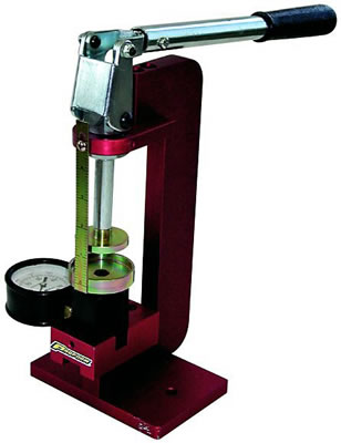
it sure looks like these gals were selected because they look good in a video, and they probably had a 3 minute long ..Q-card based education on what to say and do, for the VIDEO.....if it was my choice and looking at the tools vs what they do for me I'm rather inclined to spend $515 and get something REALLY USEFUL

$220 for this

http://www.summitracing.com/parts/pro-67597/overview/
pro-67597_cp.jpg


$268 for this
http://www.summitracing.com/parts/pro-66774/overview/
pro-66774_5_w.jpg


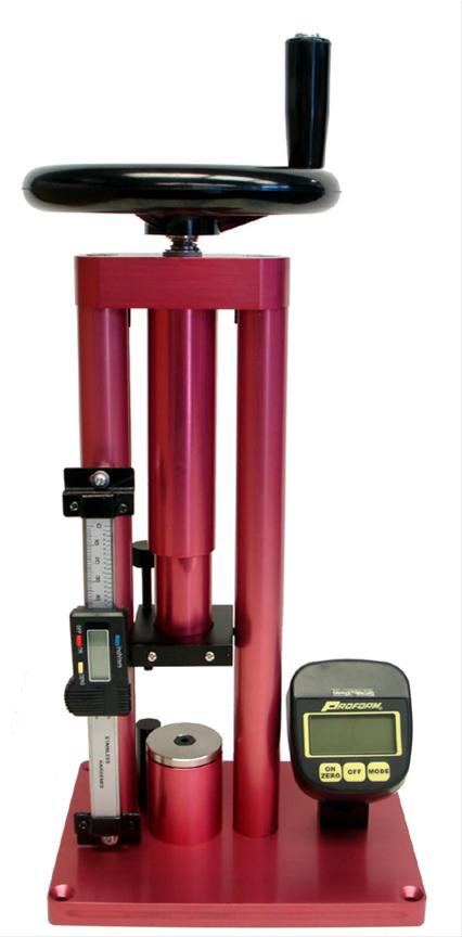
$515 for this
http://www.summitracing.com/parts/pro-66776/overview/
PRO-66776_xl.jpg


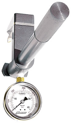
PROFORM's new billet aluminum 1000 lb digital bench top spring tester is the most accurate way to check spring pressure. Check springs up to 1.5" in diameter and 3 7/8" in height. Digital display reads in 1 lb (0.5 kg) increments, and has a back lighting feature. Peak hold and automatic shutoff are other included features. Search part number 66776 at ProformParts.com for more information.


http://www.summitracing.com/parts/pro-66776


http://www.buxtonengineering.com/on_head_valve_spring_tester.php

http://www.racingsprings.com/1300-Series-/1300-Series-/sku/33

http://www.racingsprings.com/1500-series/sku/34

good quality valve springs are fairly expensive, youll generally pay $250-$450 for decent valve springs and many guys start looking for far cheaper imported sets, that are of lower quality, at bargain prices, the problem is that you generally find a set, and comparing the price it makes it hard for some guys to remember YOU GENERALLY GET WHAT YOU PAY FOR AND THERE'S A DARN GOOD REASON THE IMPORTED PARTS ARE CHEAPER


rockerdiagram5.JPG

installedheight.gif


viewtopic.php?f=44&t=2839&p=7344&hilit=adjustable+guide#p7344

viewtopic.php?f=52&t=126&hilit=louis+rocker
adjustablesbc.jpg


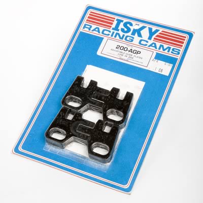
and you may need too use the correct adjustable guide plates when you find the push-rod alignment is in need of minor tweaking to get the clearance and geometry correct

STUD-12.jpg

louis1.jpg

louis.jpg


using a louis tool, this tool is a GUIDE /tool for use with a high quality DRILL, its made of HARDENED STEEL that FORCES the DRILL BIT to drill thru the head to correctly lengthen the push-rod slot for increased clearance, they usually come WITH INSTRUCTIONS AND THE NECESSARY DRILL


if the cam and lifter break-in failed during the cams break-in,
theres a very good chance you have a clearance or valve train binding issue some place like spring bind or rocker to rocker stud or the wrong valve train geometry
reading the links and sub links will save you a great deal of problems
http://garage.grumpysperformance.com/index.php?threads/cam-wear-articles-you-need-to-read.282/
http://garage.grumpysperformance.co...k-after-a-cam-lobe-rod-or-bearings-fail.2919/
http://garage.grumpysperformance.com/index.php?threads/oil-system-mods-that-help.2187/
http://garage.grumpysperformance.co...s-and-improved-oil-flow-mods.3834/#post-10199
http://garage.grumpysperformance.co...-in-vs-threaded-rocker-studs.2746/#post-90509
http://garage.grumpysperformance.co...train-clearances-and-problems.528/#post-79273
http://garage.grumpysperformance.com/index.php?threads/using-rare-earth-magnets.15981/
http://garage.grumpysperformance.com/index.php?threads/rocker-push-rod-wear-issues.9815/
http://garage.grumpysperformance.co...-pushrods-and-check-info-you-might-need.5931/
 
Last edited by a moderator:
if you have a cam lobe or lifter fail, in about 99% of the cases its not a (BAD CAM) its a clearance or lubrication or valve train geometry issue, you need to correct or its almost sure to be repeated.
if you have not replaced the cam bearings and other bearings and cleaned the passages in the block after a cam fails chances are very good it will continue to happen, all that metalic dust from the cam lobes and lifters did not and never does get 100% trapped by the oil filter, and it only takes a bit circulating with theoil flow to start screwing up the new lifters and cam lobes.
Starting with a clean block,getting the clearances correct, and adding a couple magnets and a baffled oil pan with 7-8 qts capacity will be a good start, making 100% sure the valve train clearances and geometry and spring load rates are correct goes a long way toward preventing future problems......just slapping a new cam and lifters into the block after a cam failure has a low chance of having good long term durability.
use of quality oil filters , high capacity oil pans and ADDING magnets , and use of a good MOLY assembly lube tend to limit the chances of crud getting into the contact points between the lifter and cam lobe but checking all the clearances, geometry and spring load rates will prevent many failures.
BTW having exceeded the design limits of the valve train (GETTING INTO VALVE FLOAT) tends to damage cams and lifters also

worth reading thru

http://www.iskycams.com/camwalk.php

http://www.iskycams.com/degreeing.php

http://www.hotrod.com/articles/best-tips-breaking-new-camshaft/

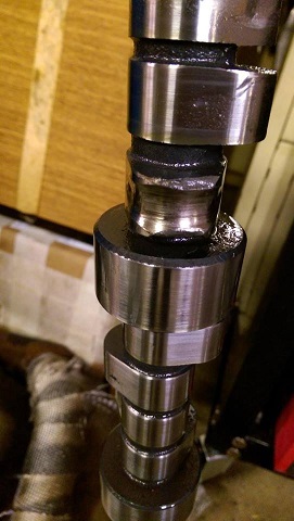
high spring loads don,t play well with roller cams over long term use, heres a very clear example of why you should only use Billet cam cores with roller cams having over about 320 lbs of spring pressure and why you MUST verify valve train geometry and clearances.


wornrollercamlobe.jpg


wornrollercamlobe1.jpg


rollerlifter.jpg

billetcam.jpg


distriboila.jpg

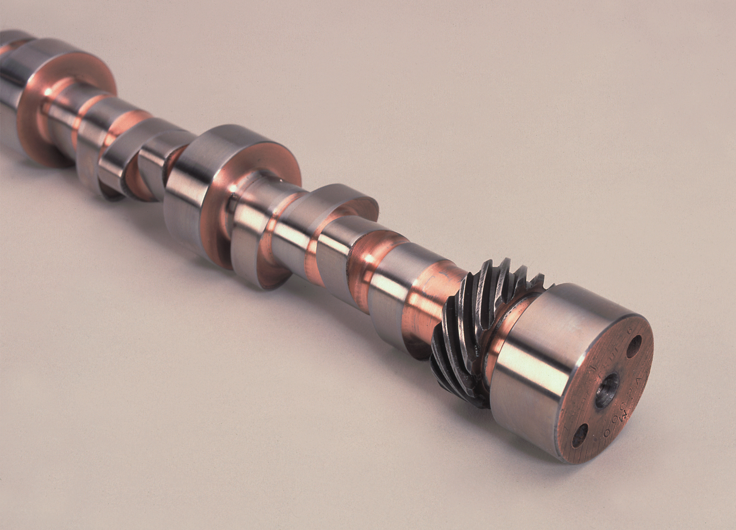
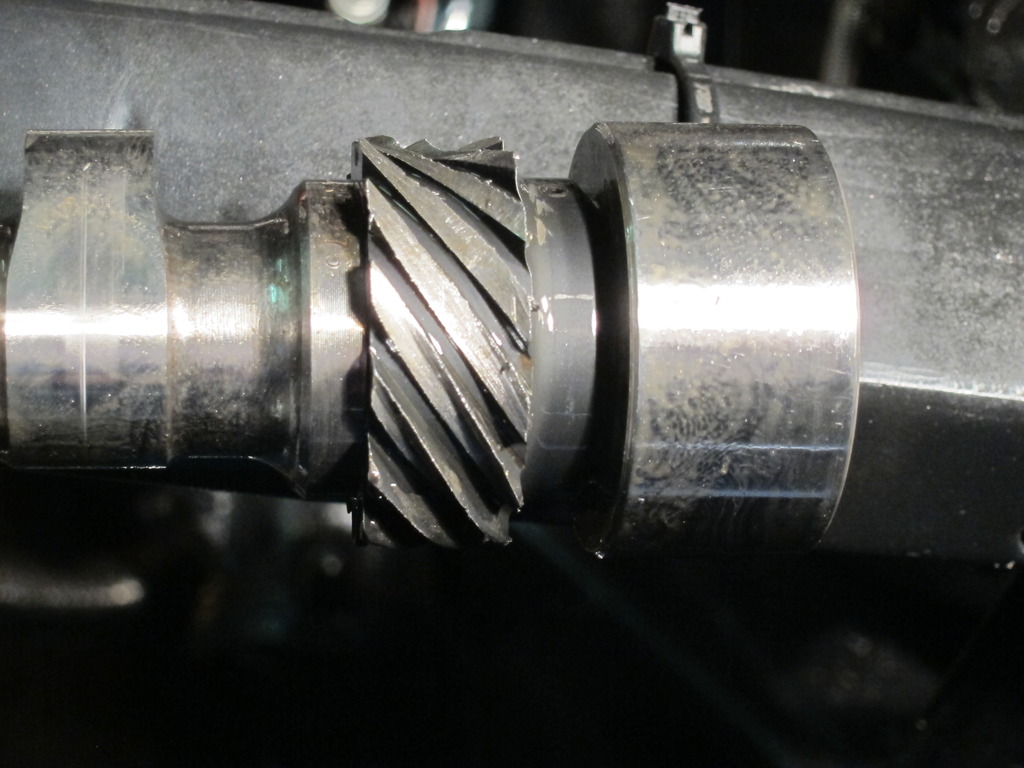
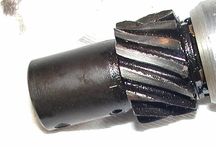
get the cam gear material match to distributor gear material match,wrong or oil flow match incorrect and rapid wear can result
campressgear.jpg


distgear2.jpg

camgearfg.png

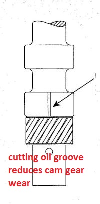
make sure the oil groove lines up with where the gears mesh when the distributors installed and timed correctly.
p114223_image_large.jpg
 
Last edited by a moderator:
If you think you have a worn cam lobe, it will not open the valve completely, while a stuck or burnt valve won,t close completely, remove the compression tester and [color]squirt some oil into the cylinder and retest, if it bumps the readings up significantly its not likely to be a result from a worn cam lobe, but it might be from bad rings or a burnt or non-seating valve[/color],
your best course is to pull the valve covers and carefully watch the rockers,and measure the lift at the retainer, with a dial indicator and a magnetic base while you slowly turn the engine by hand if you find a suspect worn cam lobe,when cam lobes wear they usually eat lifters and cause other damage thats measurable at the rocker/retainer

http://www.harborfreight.com/cpi/ctaf/d ... umber=5645
05645.gif


http://www.harborfreight.com/cpi/ctaf/d ... number=623
00623.gif

viewtopic.php?f=62&t=881&hilit=leakdown%E2%80%A6

If you find a flat tappet lifter that's not pumping oil, you'll need to inspect closer,and try adjusting the preload or lash carefully,flat tappet lifters need to spin freely in their bores to prevent wear,if the cams undamaged (UNLIKELY) yes you can just drop a well lubed (use molly assembly lube)new lifter onto the lobe and adjust the valve preload/ or lash clearance and your good to go, but carefully inspect the cam lobe thru the lifter bore once its out and any resistance to the lifter sliding up out of the bore usually indicates BOTH the lifter base and cam lobe are damaged and you need a new cam/lifter set, then place a high pressure air hose on the cylinder after you bring the cylinder up to TDC on the COMPRESSION STROKE, and listen for air leaking out of the exhaust or intake indicating a burnt or bent valve

I know some of you gentlemen would rather dig your own eyes out of your face with a rusty fork than read links, sub-links and posted info, but amazingly there useful info , in them, like tools that let you detect cam wear early, when to swap filters
what lubes to use,how to adjust and clearance valve trains, use of magnets to trap metallic crud and limit damage, which filters to use, etc.

the total amount of assembly lube you put on the cam and rotating assembly rarely can exceed 4 OZ and that EASILY fits into an oil filter, so if your getting more crud than the first oil filter traps in the first 30 minutes during the engine brake-in process, logic says its COMING from someplace and a quick look at the filter internals with the tool linked above and the magnets you should have installed should give you a good idea as to the source

http://store.summitracing.com/partdetail.asp?autofilter=1&part=SUM-900510&N=700+115&autoview=sku
sum-900510.jpg


http://forum.grumpysperformance.com/viewtopic.php?f=44&t=799&p=1161#p1161

http://forum.grumpysperformance.com/viewtopic.php?f=32&t=939&p=1582&hilit=+filter+tool#p1582

http://forum.grumpysperformance.com/viewtopic.php?f=52&t=282

http://garage.grumpysperformance.com/index.php?threads/valve-spring-cooling-via-engine-oil.6491/

http://www.summitracing.com/search/?keyword=break in ratio rockers&dds=1


there ARE reduced ratio roller rockers designed to significantly lower the lifter to lobe pressures during the cam break-in process, and its a whole lot easier to swap rockers during the break-in process than swap to lower pressure springs or remove inner springs from dual spring valve trains during the break in process
 
Last edited by a moderator:
JUST SOME VISUAL REMINDERS OF WHAT FAILING TO CHECK CLEARANCES, high spring load rates, lack of lubrication, cheap parts, and excessive rpms RESULTS IN
vincam.png


read this link
https://www.crankshaftcoalition.com/wiki/Camshaft_install_tips_and_tricks

12. Failure to clearance lifters in their bores.


Grooved lifter bores
Lifter clearance should be 0.0012" to 0.002", with 0.0015" (one and one half thousandths) considered close to ideal. Too loose can be as bad as too tight. One way to provide a flat tappet cam and lifters with additional lubrication is to groove the lifter bores. One tool for doing this operation is the Comp Cams p/n 5003 lifter bore grooving tool sold by Summit. Solid lifter flat tappet lifters are available with a small machined hole in the lifter foot that feeds pressurized oil to the interface between the cam and lifter. But having that hole is no guarantee (see photo below)...


GET THE CLEARANCES or VALVE TRAIN GEOMETRY WRONG OR OVER REV THE ENGINE, OR FAIL TO PROVIDE CONSTANT LUBRICATION, AND BAD THINGS CAN OCCUR, as can ASSUMING THE CLEARANCES ARE CORRECT IF YOU DON,T CHECK
bent_valve.jpg


IT helps to know exactly what year and casting number your engine block is as early production big block engines used a different rear cam bearing and cam, a potential rear cam bearing oil flow issue is found on the 1965- too a few very early 1967 engines ,if you install the older design BBC cam with a grooved rear main in EITHER config with EITHER rear bearing your covered, and since thats just not expensive and any decent machine shop can modify any cam like that cheaply is the smart route to take if your in doubt. obviously having the machine shop groove the rear cam journal under the cam bearing in the block like the later BBC engines would be ideal.

camjournal.jpg

1965396CamOilGroovea.jpg

http://garage.grumpysperformance.com/index.php?threads/cam-bearing-install-tools-install-info.1479/


http://garage.grumpysperformance.co...k-after-a-cam-lobe-rod-or-bearings-fail.2919/

http://garage.grumpysperformance.com/index.php?threads/cam-wear-articles-you-need-to-read.282/

rlcf1.jpg

rlcf2.jpg

rlcf3.jpg

04907.jpg


Picture007-4.jpg


Picture004-4.jpg


Picture009-2.jpg


IMGc_4925.jpg


melt2.jpg


Rodbolts.jpg


IMGc_4916a.jpg


Picture006-5.jpg


BE aware you need to verify rocker adjustment lock nut to rocker slot clearance and yes it varies even with the same manufacturers different rocker designs
rockerh1.png

rockerh2.png


rockerbin.jpg

rockertrunion1.png


ft4.jpg


rodbearingcont1.jpg


the result of debris in the oil, embedding in bearing surfaces , from only one lifter and cam lobe wearing for short time or so.
 
Last edited by a moderator:
bronze_distributor_gear.jpg

billet cams can and do have steel distributor gears that are not compatible with stock cast iron or melonized stock distributor gears, so anytime you change cams get and correctly install the matching distributor gear


read the linked info
https://www.onedirt.com/tech/engine...fusion-out-of-distributor-gear-compatibility/

http://garage.grumpysperformance.com/index.php?threads/shiming-a-distributor.251/#post-1366

camgearfg.png

Preference on assembly lube?

50% marvel mystery oil
marvel.jpg

and 50% crane moly lube, or the paste moly, the mix of moly paste and M.M.O. is generally applied liberally with the paint brush, in multiple applications to surfaces like cam gears, timing chains, lifters, rockers, and cam lobes, to provide an extra layer of lubrication protection on initial engine start up.
crn-99004.jpg

what Ive used for decades
but this works

permassembly.jpg

I have used J&B WELD EPOXY on a large magnet
https://www.zoro.com/value-brand-ring-magnet-98-lb-pull-10e797/i/G4187224/
Z_o3v-kcpEx-.JPG


on the base of an aluminum 1/2 cup measuring cup I purchased at a yard sale for 25 cents to mix up the mixture, the magnet allows me to stick the cup to the block oil pan rail or engine stand where its handy too get at, and I simply brush on the mix with a 1" paint brush, with synthetic bristles that won,t shed
molypaste.jpg

OH! slide it off the block don,t try to just pull it off , its going to be much less messy that way trust me!
when your done , wipe it clean and stick it inside the lid of your tool box , after placing it in a ziploc bag to prevent it from picking up trash while in storage

1aae7f99-2e0a-4629-aae6-e646e15a8533_1000.jpg


shopping


bronze_distributor_gear1.jpg

keep in mind theres a VAST difference in the QUALITY of bronze distributor gears and alloys vary wildly so its best to both use the cam manufacturers input during selecting components and not to assume all bronze gears are interchangeable
 
Last edited by a moderator:
bluesfella said:
In the middle of replacing the valve stem seals on my SBC (290hp GM crate motor from 8-10 years ago), I came across this pushrod that isn't coming all the way back up:

3vexi2ocv.jpg


I used a mirror and a flashlight to make sure the pushrod in seated properly on the lifter, and maybe I'm imagining it, but it does kind of look like the lifter isn't all the way up.

And I rotated the engine around a couple of times to make sure it wasn't just in the down position. This pushrod does go up and down, it just seems to do it much lower than the rest.

Do I have a collapsed lifter? If so, can I pull the heads and replace the lifters, or should I also suspect the cam maybe has a lobe damaged?

I've pulled heads before, but never replaced a cam, so I'm a little nervous about that job.

Thanks!
selfalighningrockertx.jpg

If I had to guess it would indicate a well worn cam lobe WHY?
because the lifter seat in a hydraulic lifter only moves about a bit less than .100 inch from full up to full down, thus it appears you have far more clearance indicating a well worn lifter and cam lobe, obviously checking with a degree wheel and dial indicator won,t hurt and removing the intake manifold and pulling the lifter so you can carefully inspect BOTH the lifter base and cam lobe would be a good idea at this point to prevent a great deal more metallic trash from getting into your bearings, if the cam lobes wearing away

measuringclearance.jpg

http://www.summitracing.com/parts/pro-66830

http://www.summitracing.com/parts/pro-66830/overview/
pro-66830_cp.jpg

liftc1f.jpg

worn5.jpg


6301a.jpg

6301b.jpg

6301c.jpg


66962.jpg

66797.jpg


https://www.harborfreight.com/multipositional-magnetic-base-with-fine-adjustment-5645.html

bv93fans.jpg

https://www.harborfreight.com/catalogsearch/result/index/?dir=asc&order=EAScore,f,EAFeatured+Weight,f,Sale+Rank,f&q=indicator+stand

Rocker1closed.jpg


Rocker2mid-lift2.jpg


Rocker3fulllift.jpg

Liftersdif.jpg


hylifters.jpg


worn5.jpg

http://garage.grumpysperformance.com/index.php?threads/basic-info-on-your-v8-lube-system.52/

http://garage.grumpysperformance.com/index.php?threads/oil-system-mods-that-help.2187/

http://garage.grumpysperformance.com/index.php?threads/cam-bearing-install-tools-install-info.1479/

http://garage.grumpysperformance.com/index.php?threads/installing-an-oil-pump-pick-up-tube.1800/

http://garage.grumpysperformance.com/index.php?threads/bearings-and-oil-flow.150/

http://garage.grumpysperformance.co...oil-passages-and-improved-oil-flow-mods.3834/

http://garage.grumpysperformance.com/index.php?threads/testing-a-chevy-oil-pump.6479/
 
Last edited by a moderator:
Going to play it safe with the Olds 425 Grumpy. Let the Massive torque do the work.
$400 I figure to get it in and do it.$100 For Tags.
T/A HAS GOOD STUFF. LITTLE LATER IN 015.
 
http://www.enginebuildermag.com/2006/07/vizards-view-avoiding-flat-tappet-cam-and-lifter-failure/

vizard said:
There is nothing worse than building a cost effective engine for a customer, shipping it, and then having it come back a short while later with the installed flat tappet cam wiped out. Even if the cam and valve train was warranted by the cam manufacture, you, as the engine builder, will bear the brunt of the rebuild cost.

In many cases, it’s a little more than just replacing the offending parts as hard iron debris will have gone a round of the engine and basically set the scene for further failure down the road. My intent here is to show how to minimize the flat tappet cam failure primarily seen with domestic V8s.

Numerous reasons exist for cam/lifter failures and, not surprisingly, numerous steps to prevent such failures. Basically, the preventative measures fall into two groups: those done while the engine is being built and those done at or after customer hand-over.

Just to simplify things I am going to discuss most of what is covered in terms of hydraulic cams. However, most everything also applies to solid cams, especially those high acceleration ones used for limited lift race classes. Let’s make a start at the potential source of the problem – the cam profile itself.

Selecting the Profile
Flat tappet cams are great at opening valves quickly. Contrary to popular belief they can out-accelerate a roller by a hefty margin if the cam designer so chooses it to. There are safe profiles, and there are power orientated profiles, and just about everything between. The key to knowing which profile you may be selecting is determined by its “hydraulic intensity.” This term, coined by Harvey Crane, describes the rate of lifter rise imparted by the profile. This number, for a hydraulic cam, is found by subtracting the 50 thousandths duration figure from the 6 thousandths duration figure.

Most factory cams have a hydraulic intensity in the region of 70°. Originally such large, and consequently low intensity, figures were the result of mild profiles brought about, in part, by cam cores having far less surface load bearing capabilities than current cam cores. Be aware that some cheap cams are ground on cores, which cannot support high surface stresses. If you feel the need to use such cams understand that you will need to apply extra diligence to the selection of other parts in the valve train and to the care of the valve train during subsequent assembly. My advice here is buy cams from a company that uses top grade cores.

If nothing else leads to its downfall, a profile ground on a good core can have a hydraulic intensity of 50° – 55° and be a pretty safe bet in terms of reliability. There are, however, many flat tappet cam profiles to be had, which offer substantial increases in performance by pushing the hydraulic intensity boundaries. All the big cam companies such as Crane, Crower, Comp, Lunati and Isky have them and, to stay competitive, they keep pushing the envelope. Lunati’s new Voodoo range is a prime example here and recent tests in a big block Chevy showed they certainly delivered as promised.

The problem of wiping out flat tappet cams could be prevented by going to a roller design. Two problems here: one is that a roller calls for more money; and two, unless the roller has a seat duration longer than about 270° to 275°, the flat tappet cam is likely to out-perform it.

In case you doubt the validity of this just check out the hydraulic intensity and lift figures of Comp Cams Xtreme Energy range of rollers and flat tappet cams. Although a crude comparison, the numbers indicate that until about the 270° mark is exceeded, a flat tappet cam is likely to give more opening area under the lift curve. If you want to impress a customer with the power you can build into a relatively low cost unit the higher intensity cams from any reputable company are the type to use. Now let’s see how to make them safe.

Taper and Crown
In reality, there is no such thing as a flat tappet cam and lifter. The lifter has a crown on it, typically between .050? and .100? radius. This runs on a cam profile, which is tapered across its form. The cam profile itself does not run centered on the lifter but is offset to one side. The combination of this offset and the cams taper and the lifter crowning causes the lifter to rotate. At the end of the day it is the lifter rotation (which considerably reduces the rubbing speed) that saves the situation from a sure disaster.

To make sure that the system works as it should first measure each lobe on the cam you intend to install and check that it has at least one thousandth taper across the lobe (1.5 to 2.5 are typical). For a Chevy the largest dimension should be toward the back of the cam. On any others the largest dimension should be on the side of the profile that runs toward the outside of the lifter diameter.

Next check the lifters. It’s unlikely you’ll find one wrong, because quality control on these items is very high. But you can make a quick check by just putting the face of two lifters together and holding the pair up to the light. This will quickly establish that the crown exists.

The type of lifter you choose can also be instrumental in extending the life of the valve train. More expensive hard face lifters as supplied by most cam companies are well worth it, especially if you’re building a big block Chevy, which is more prone to lobe and lifter failure. And be aware that many cam companies offer a cam hardening service, which is also well worthwhile.

Added Lifter Lubing
Part of the problem of inadequate lifter/cam interface lubrication can be offset by simply using more oil at the offending sight. With a solid lifter this can be done by having a lifter with a small hole in its face, thus connecting the well of the lifter to the face.

For any V8 flat tappet cam the best way to provide additional oiling is to groove the lifter bores. This involves cutting a groove in the lifter bore that, at the upper end, connects to the longitudinal oil passage. The lower end terminates at the bottom of the lifter bore and directs a small stream of oil directly onto the approaching side of the cam. Comp Cams has a tool that does this job and at about 15 seconds a bore, it is quick and easy to use. Most importantly though, it is effective, especially on big block Chevys.

Assembly
After checking cam profile taper and lifter crowning it’s time to get down to assembly. Before actually installing the cam check that every lifter rotates freely in its respective bore. Without freedom of rotation the lifters will be in for a short life. Once lifter rotation is established it’s time to lube up the cam profiles and lifter faces with a break-in lube. Usually there is a packet of break-in lube included with the cam but for what it’s worth the difference between a good break-in lube and a top-of-the-line break-in lube is quite substantial.


About 15 years ago, I did a test using a Pinto engine as a guinea pig. What was done here was to install a cam and followers and instantly fire up the engine and turn it to 6,000 rpm with no break-in whatsoever. This pattern of events was used to test various break-in lubes.

Moly grease-based break-in lubes proved to be at least twice as effective as even the best unaided oils. At the time (remember this was 15 years ago) the clear winner for the best break-in lube was from Crane. This was several orders of magnitude better than the results achieved with moly grease. A point to note here is that break-in lubes are just that. Some of these break-in lubes can, if used for too long a period,

http://www.dragzine.com/tech-storie...-lifters-still-viable-in-performance-engines/
 
This Cam Glossary was created by Elgin Cams to help provide our clients a tool which they can in turn use to decipher all the cryptic acronyms used in the cam grinding industry. Hope you find it useful.

ABDC:

Crankshaft degrees After Bottom Dead Center.

ADVERTISED DURATION:

See: “SEAT DURATION.”

ATDC:

Crankshaft degrees After Top Dead Center.

AREA UNDER THE CAM LIFT CURVE:

The area under the bell-shaped lift curve is depicted with lift drawn on the vertical axis and degrees of crankshaft rotation on the horizontal axis. The greater the area under the lift curve, the greater is the lift and/or duration at some point on the cam lobe profile.

BASE CIRCLE:

The round portion of the cam lobe, concentric with the cam axis, where lobe lift is zero and valve lash adjustments must be made. This portion of a lobe is also called the heel.

BBDC:

Crankshaft degrees Before Bottom Dead Center.

BTDC:

Crankshaft degrees Before Top Dead Center.

CAM FOLLOWER:

See “TAPPET”.

CAM LIFT:

This is the maximum distance that the cam pushes the follower when the valve is fully open. Cam lift differs from valve lift. See “GROSS VALVE LIFT.”

CAM MASTER:

After the design of a new cam is computed, its dimensions are transferred to a precision template called a master. The master is then installed in the cam- grinding machine to generate the shape of the lobes onto the finished cam.

CAM PROFILE:

The finished shape of a cam lobe. Its segments are the base circle (or heel), a short opening clearance ramp, the opening flank, the nose, the closing flank, and a short closing clearance ramp onto the heel again. See further entries for each segment, and also “LOBE TAPER.”

CAM VELOCITY:

The rate of change in lobe lift per degree of cam rotation, either positive (while opening) or negative (closing). The highest velocities occur on cam flanks, the slowest velocities on the ramps. Velocity is rendered visual on a lift graph, as the slope of the curve at any point.

CAMSHAFT:

A shaft containing many cams (or lobes) that convert rotary motion to reciprocating (lifting) motion in an internal combustion engine. For every two revolutions of the crankshaft, the camshaft(s) rotates one revolution. The lobes on the camshaft actuate the valve train in a phased relation to piston movement. The camshaft determines when the valves open and close, how long they stay open, and how far they open. A complete camshaft also contains journals (mains) that the shaft rotates on and a fixture at one end for the drive gear, plus (depending on the engine) perhaps a distributor/oil pump drive gear, fuel pump eccentric, tachometer drive, and/or oiling holes.

CARBURIZING:

Gas carburizing is a heat-treatment process for steel camshaft billets. In this procedure, the camshaft is placed in a furnace with a carbon-gas atmosphere and heated to a specific temperature. After the camshaft surface has absorbed a desired amount of additional carbon, it is removed from the furnace and quenched to attain the proper temper.

CAST BILLET:

A term to describe a camshaft that is made from a casting. The material for the casting is a special grade of iron alloy called “Proferal”, which is used primarily for non-roller camshafts because of its excellent anti-wear characteristics.

CHEATER CAMS:

See: “IMPROVED STOCK CAMS.”

CHILLED IRON LIFTER:

A cam tappet/lifter made from high-quality iron alloy that is heat-treated during its casting. Molten iron is poured into a honeycomb mold with a chilled steel plate at the bottom, to quench and so heat-treat the face of the lifter. This type of tappet is compatible only with steel and hardface overlay cams.

CLEARANCE RAMPS:

Two short segments of the cam lobe, between the base circle and either flank. Ramps change the lift at a constant, slow speed, in theory to compensate for small deflections and slack in the valve train. The opening ramp takes up all clearance in the valve train and brings the valve to the verge of opening. The closing ramp sets the valve on the seat, and ends when the tappet returns to the base circle. Ramp designs have extraordinary effects on power output and valve train reliability.

COIL BIND:

A valve spring that has been compressed to the point where there is no space between the coils, where the coils are stacked solid, is in coil bind. The valve cannot open any further from this point.

CONCENTRIC:

In machining, having the same center, or running true. I camshaft terminology, the cam bearing journals and lobes are concentric with each other when the camshaft is straight, and there is .001” or less runout between all the cam lobes and journals.

DURATION AT .050”

The degrees of crankshaft rotation from when the valve is lifted open .050” until it is .050” from closing.

FLAME HARDENING:

A heat-treating process in which a camshaft is exposed to an open flame and then quenched (cooled) in oil.

FLANKS:

The two sides of each cam lobe face, the segments that lie between the nose and the clearance ramps before the base circle.

GRIND:

Specifically, the process of shaping cam lobes on a specialized cam-grinding machine. In gearhead slang, the general profile of a cam independent of application, as in “drag race grind” or “Street Hemi grind.”

GROSS VALVE LIFT:

A nominal total valve lift measurement estimated by multiplying the highest cam lift by the rocker arm ratio. This cannot actually be attained in a running engine, due to valve lash or hydraulic lifter bleed-down, plus clearances and flex in the valvetrain. Production tolerances in rocker arms further vary this figure by as much as .015” plus or minus. See: “NET VALVE LIFT.”

HARDENABLE IRON LIFTERS:

A cam follower made from a special high-quality iron alloy that is compatible with cast iron billet camshafts. The entire cylindrical body of a hardenable iron lifter is hard, in contrast to a chilled iron lifter with only its base hardened.

HARDNESS:

By engineering definition, resistance against penetration. For cams and lifters, hardness is directly related to resistance against wear. A typical iron cam registers in mid- to high-40s on the Rockwell C scale (Rc). Compatible lifters register five to ten points higher. The smaller part, running hotter, must be harder to equalize wear between parts.

HEAT TREATMENT:

A number of heat-cycle processes to alter the surface hardness of a metal. The temperature of the part is raised to less than its melting point, held there for a specified time, then allowed to cool at a specified rate to nearly room temperature. This heat cycle alters the crystal and grain structures of the metal, which affect its hardness. Some processes also diffuse carbon or nitrogen atoms into iron surfaces. All flat and roller tappets are heat treated. Some iron cams (mostly British) are heat-treated after re-grinding, to regain surface hardness. See: “CARBURIZING, CHILLED IRON LIFTER, FLAME HARDENING, HARDNESS, INDUCTION HARDENING, NITRIDING, and QUENCHING.”

HEEL:

See: “BASE CIRCLE.”

HYDRAULIC VALVE LIFTERS:

Lifters with an inner mechanism fed by engine oil, designed to maintain constant zero lash in the entire valve train. Their advantages include quieter engine operation and elimination of periodic adjustmentS to maintain proper lash, as required with solid valve lifters. Hydraulic lifters do, however, maintain a constant pressure against the camshaft, which solid lifters do not. Therefore the anti-scuff additives in lubricating oils are more essential with hydraulic lifters. See: “ZDDP.”

IMPROVED STOCK CAMS (CHEATER CAMS):

An improved stock cam has stock lift and duration, but the flanks are modified so that they are faster acting. Such a process increases the area under the lift curve by about a 5%. That means that there will be a power increase across the entire rpm range of the engine. This type of custom grind works very well in engines with fuel injection systems that calibrate off manifold vacuum, which are therefore very sensitive to changes in camshaft duration.

INDUCTION HARDENING:

An electrical heat-treating process in which a ferrous part is placed inside a coil of heavy wire through which a high-frequency current is passed. Through the electro-magnetic phenomenon of induction, energy transfers from the coil to the part. The part inside the coil becomes cherry red almost instantly, and is then quenched. The quench medium is either water (for large parts, like cam billets) or oil (for small parts, like needle bearing rollers, to forestall cracking).

INTERFERENCE FIT:

There is a slight press fit between dual valve springs, if the outside diameter of the inner spring and inside diameter of the outer spring approximate each other. The slight friction between them produces a damping effect on spring vibration and surge. See: “SPRING SURGE.”

LASH (VALVE LASH):

Valve train clearance, usually measured at the valve tip, opens up necessary clearance between the base circle of the camshaft lobe and a solid camshaft follower or tappet, so that the valve is certain of closing and staying closed when the tappet is on the lobe heel.

LIFT GRAPH:

After installing a camshaft in a block or head, a mechanic can plot the lift of the cam in relation to each degree of camshaft rotation. Install a dial indicator on the cam follower or tappet and a degree wheel on the crankshaft. Rotate the crankshaft in five-degree steps, and take a lift reading from the dial indicator at each interval. Then plot the readings on graph paper, with cam lift on the vertical axis and degrees of crankshaft rotation on the horizontal axis.

LIFTER:

See “TAPPET.”

LIFTER PRINT (CAM PRINT):

The amount of travel that a rotating cam lobe makes across the lifter face. Since the cam lobe must not run off the edge of the lifter, lifter diameter determines the maximum usable flank velocity for a cam. See: “CAM VELOCITY.”

LOBE:

Each lobe face is eccentric to the cam journals and transmits a lifting motion through the valve train to operate the valves. The design of the lobe determines the usage of the camshaft, e.g. street use or all-out competition.

LOBE CENTERS-CAM:

The difference measured in cam degrees between the centerline of the intake lobe (its point of highest lift) and the centerline of the exhaust lobe in the same cylinder.

LOBE CENTERLINES-VALVE:

The point on each lobe, measured in crank degrees from TDC, at which the valve is most fully open. For one example, take a cam that measures full intake lobe lift at 110 degrees ATDC and full exhaust lobe lift at 110 degrees BTDC. This camshaft was ground with 110-degree lobe centers and is ground timed “straight up”, neither advanced nor retarded. As another example, a different cam measures full intake lobe lift at 105 degrees ATDC and full exhaust lobe lift at 115 degrees BTDC. This camshaft was also ground on 110-degree lobe centers, but it is advanced by five crankshaft degrees.

LOBE TAPER:

The small amount by which one side of a flat-tappet lobe is larger than the other, even though both follow the same profile. Cams carry taper left or taper right and zero to .003” taper, depending on the engine. The direction and amount of taper is measured best across the diameter of the base circle. Hold the front of the cam to your left (as a cam-grinding machine does). If the forward (left) side of the lobe is larger, that is taper-left (TL). If the rearward (right) side of the lobe is larger, that is taper-right (TR). All lobes should measure with the same amount of taper, but not necessarily the same direction. TR pushes cams into the block, off the angled pressure from tappets. Engines with TL, mixed tapers, or roller tappets (with no taper) require a cam thrust plate. Lobe taper works with tappet crown and tappet bores offset from lobes bores to drive flat tappets into rotation. See: “Tappet Crown, Tappet Rotation.”

MAINS (JOURNALS):

Cylindrical surfaces on a camshaft, concentric with the camshaft axis, which ride in bearing surfaces to support the camshaft in an engine block or head(s).

NET VALVE LIFT:

The probable lift of the valve, determined by subtracting the valve lash dimension from the gross valve lift figure. But production tolerances in rocker arms can vary this figure by as much as .015” plus or minus. So can poor geometric designs of rocker arms, e.g. in Chrysler Slant 6, Ford FE, and many aftermarket rockers. So does flex in the valve train, especially pushrods. See: “GROSS VALVE LIFT.”

NITRIDING:

Gas nitriding is a surface heat treatment that leaves a hard case on the surface of an iron cam. The hard case is up to .010” deep and is typically twice the hardness of the core material. The process is accomplished by placing the cam into a sealed chamber filled with ammonia gas, and heating it to approximately 950 degrees F (510 degrees C). At this temperature, a chemical reaction occurs between the ammonia and iron of the cam to form ferrous nitride on the surface of the cam. As the reaction progresses, ferrous nitride diffuses into the cam core to a case depth of approximately .010”. The nitriding process is done at relatively low heat (as heat treatments go), so the core material loses no hardness. Also, the chamber temperature is raised and lowered slowly, so that the cam is not thermally shocked, which would create internal strains. Gas nitriding was originally intended for where sliding motion between two parts occurs repeatedly, so it is therefore directly applicable to solving camshaft wear problems. Ferrous nitride is a ceramic compound, which accounts for its hardness. It also has some lubricity when sliding against other parts.

NOSE OF THE LOBE:

The portion of a cam lobe highest from its base circle, activating full lift position.

OHC:

Overhead Cam engines. In this type of engine the cam is positioned in the head, above the valves. (e.g. Porsche 944 engine)

OHV (PUSHROD ENGINES):

Overhead Valve engines. In this type of engine, the camshaft is positioned in the block, beneath the valves in the head. (e.g. Chevrolet 350 c.i.d. V8 engine)

OVERLAP:

The angle in crankshaft degrees when both the intake and exhaust valves are open at the same time. This occurs when the piston is near Top Dead Center on the exhaust stroke. The greater the seat-to-seat duration on the intake and exhaust lobes and the less their lobe centers-cam, the greater the overlap will be in crankshaft degrees. See “LOBE CENTERS-CAM and SEAT DURATION.”

PARKERIZING

A thermo-chemical surfacing process, whereby a nonmetallic, oil-absorptive coating is applied to the outside surface of the camshaft except on the mains (journals). The lubricity of this coating permits rapid break-in of cam lobes without scuffing. (The Parker family developed this process in NJ in the 1920s.)

PROFERAL IRON:

See “CAST BILLET.”

QUENCHING:

The final stage in ferrous heat-treating processes is cooling the workpiece nearly to room temperature. The rate of cooling affects the resulting microstructure in metals, and from that either hardness or toughness. Quenching cools the fastest and generates the hardest surface. The quenching liquid is often water for large parts, but must be oil for very small parts (like needle bearing rollers) to prevent them cracking from thermal shock.

ROCKER ARM GEOMETRY:

Any OHV rocker arm must comply with geometric law to transfer the lift curve of the cam properly into the valves and valve springs. The rocker’s three centroids (centers of motion) must lie in a straight line: its contact cone with the pushrod tip, its axis of rotation, and either the axle of a roller tip or the center of a circle extended from a curved plain tip. Centroids not in line transfer cam action non-linearly, with unpredictable effects on ranges and motions of valves and springs.

ROLLER TAPPET:

A roller tappet performs the same end function as a mechanical or hydraulic flat tappet. But instead of sliding on the cam face, this lifter contains a roller bearing at its cam face that rolls over the cam surface.

SCUFFING:

Moderate mechanical wear between two metallic surfaces sliding on each other, if and when they touch because of insufficient oil to keep them fully separated.

SEAT DURATION (SEAT-TO-SEAT DURATION):

The total time in degrees of crankshaft rotation that a valve is off its valve seat, from when it opens to when it closes. This is usually termed by production cam vendors “advertised duration”, to distinguish it from duration at .050” lift.

SPLIT OVERLAP:

The point near TDC on the exhaust stroke when both the intake valve and exhaust valve are off their seats at the same time by the same amount.

SPRING FATIGUE:

Valve springs have a tendency to lose part of their compressive strength after being run in an engine for certain periods of time, because of the huge cyclic stresses they are under. At 6000 rpm, for example, each spring must cycle 50 times per second. The immense heat generated by such stresses eventually counteracts some of the heat-treating of the spring wire, causing the springs to take a slight drop in pressure (a "set”).

SPRING SURGE:

A dynamic reaction that causes unpredictable valve spring behavior at high rpms.

At rapid reciprocating frequencies, forces put a spring coil in motion, but then its own inertia KEEPS the coil in motion. So waves of compression and rarefaction pass rapidly up and down the stack of spring coils. Moreover, at certain rpms the cam activates the spring at the spring’s natural vibration frequency, and the waves intensify. At such critical speeds, this surge effect substantially reduces the static (rated) spring strength available to operate the valve train. Clearances between parts widen. Valve motion becomes uncontrolled. Parts break.

TAPPET/CAM FOLLOWER:

A cylindrical component, either (nearly) flat-faced or roller-equipped, that rides on each cam lobe to transfer the lift action of the lobe to the rest of the valve train. One alternate name is lifter, and another term is follower. Follower is an all-inclusive term for tappets, rocker-type or finger followers on some OHC engines, and cup-type followers on most OHC engines. Rocker-type (or finger) followers slide across cam lobes, flat tappets slide across cam lobes and must also rotate in their bores, and roller tappets roll over lobes but do not rotate in their bores. Because of geometric differences in how each type of follower rides a cam lobe, each uses a different cam profile to generate the same valve-lift profile.

TAPPET CROWN:

A small amount of spherical crown ground on the faces of most nominally “flat” tappets, to prevent the edge of the tappet from riding off the edge of a tapered cam lobe. The amount of crown is determined by the amount of lobe taper, both being set by the engine manufacturer. Normal tappet wear occurs as a “donut” partway off-centered on the face. Wear near the edge indicates a tappet with too little crown for that cam. Loss of specified tappet crown indicates a worn cam.

TAPPET ROTATION:

Flat tappets must rotate in their bores, to continually present a fresh part of their face against a rotating cam, and thus equalize and minimize wear. (In contrast, roller tappets must NOT rotate at all.) Rotation is driven by offsetting the lifter bore from the center of the lobe face, lobe taper in the same direction as lifter offset, and lifter crown to match lobe taper. Before installing tappets, check that each lifter is free to rotate in its bore, and apply only engine oil (not sticky “cam lube’) on the sides of lifters. If a flat tappet does not rotate sufficiently, or at all, that lifter and cam lobe will wear out prematurely, perhaps as soon as break-in.

ZDDP:

A man-made motor oil additive essential for dry lubrication between camshafts and flat tappets, where extreme pressure squeezes away all the oil molecules. ZDDP* circulates with oil in 800-1200 parts-per-million, until it is crushed within a cam-lifter interface and plates itself into the iron surfaces. Progressive reduction in percentages of ZDDP in motor oil since 2001 is causing premature wear in many high-performance street cams. (*Zinc dialkyl dithiophosphate.) See: “HYDRAULIC VALVE LIFTERS.”

I've personally had less than impressive track record or reliable results from Comp CAMs ,
and exceptionally inconsistent results from questions their tech team answered. As a result personally I've avoided using them.(not because the products are defective, but because the tech support doesn,t seem to know what they are talking about in my experience)
theres lots of other cam suppliers available
I,ve had consistently good results from these suppliers , high lighted in green,
and would recommend them with no reservations,
based on my experience, and have seen ,
good results with the others listed, or had limited but good results


ERSON
http://www.pbm-erson.com/store.php?catId=327
http://usaperform.com/-c-154_206.html

CROWER'
http://www.crower.com/

HERBERT
http://www.dougherbert.com/

LUNATI
http://www.lunatipower.com/

CRANE CAMS
(I did a ton of business with the old crane cams, Ive not yet built a firm background with the new company but so far they seem competent)
http://www.cranecams.com/?show=technicalhelp

HOWARD
http://www.howardscams.com/howards2015.pdf


Last edited:
http://www.enginebuildermag.com/2011/08/inside-flat-tappet-camshaft-andlifter-technology/
Inside Flat Tappet Camshaft and?Lifter Technology


Roller cams have a couple of advantages over traditional flat tappet camshafts: they reduce friction, and they can be ground with more aggressive cam lobe profiles to make more power. You can also swap roller cams without having to replace the lifters. But the roller cam’s main disadvantage compared to flat tappet cams is its higher cost. A roller cam is no more expensive to manufacture than a flat tappet cam (unless it is being CNC machined out of billet steel), but the roller lifters are more complex and costly to make.

The use of roller cams is also against the rules in certain forms of racing. You can’t run a roller cam in many dirt track and circle track classes, stock eliminator drag racing (older cars), some types of marine racing and truck pulling, or vintage road racing. NASCAR rules prohibit the use of roller cams. So there are a lot of applications where a traditional flat tappet cam is the only type of camshaft you can put in an engine.

Changing Technology

The development of new camshaft profiles is an ongoing process that will never stagnate. There are a lot of proven grinds that work well in various engines. Many of these grinds have been popular for years.

But with so many stroker engines being built these days, and a proliferation of high-flow aftermarket cylinder heads for a growing number of older engines, cam grinders are always looking for the next innovation that can give their customers a performance edge over what’s currently available from their competitors.

Engines make power with their cams, cylinder heads and carburetion. All three have to work together to create the most usable power within the engine’s rpm capabilities. A huge carburetor and a killer set of heads won’t achieve their maximum power potential if the cam doesn’t have the right grind to optimize airflow. The cam lift, duration, valve overlap, lobe centers and offset also have to match the application – which creates a real challenge for the street performance engine builder who is trying to achieve the often conflicting goals of lots of power and good drivability.

Brian Reese of COMP Cams said his company has been developing new flat tappet cams for a variety of applications, including popular small block and big block Chevy, Ford and Chrysler engines as well as some of the older engines such as Ford flatheads, Ford Y-blocks and Buick Nailhead V8s.

“One of the recent improvements we’ve made is to redesign the cam itself for improved durability. We’re using a larger radius between the cam lobes and shaft. We have also increased the width of the lobes. Older style flat tappet cams have no radius where the lobes meet the cam, which creates a stress point that could lead to cracking and cam failure.”

COMP Cams also has a new line of street performance flat tappet hydraulic cams called “Thumpr” cams. According to Reese, the two things muscle car and street performance enthusiasts want most in a new camshaft is1) more power and 2) a meaner sound.
Everybody likes the rumble that a hot camshaft makes at idle. But traditional race cams that really produce a lot of power at high rpm are usually not very drivable on the street. Long duration cams with lots of overlap typically produce little vacuum at idle, have poor throttle response at low rpm, and may not produce as much torque as a stock cam until the tach hits 3,000 rpm or higher.

One of COMP Cams customers said, “I want you to build a street cam that really thumps.” So the Thumpr family of camshafts was created to satisfy both the need for more usable power and the kind of rough idle that says, “Watch out, I’m bad!”

Street performance cams need to deliver good low-end torque. Traditionally this is done by shortening the duration (the amount of time the cam holds the intake or exhaust valves open) and reducing overlap (the period during which the exhaust valve is closing and the intake valve is opening). Reducing the duration and overlap improves low end torque and throttle response, but it also makes the engine idle smoother and quieter. A wimpy sounding idle is not what most street cam customers want.

To create a hotter idle sound, Reese says the Thumpr cams have extra overlap built into the exhaust lobes to hold the exhaust valves open longer. The result is a longer and stronger exhaust pulse that really sounds great with no sacrifice in drivability or low rpm power.

The Thumpr cams are also ground on a narrow 107-degree lobe separation. For comparison, COMP Cams Xtreme Energy Cams are ground with a 110-plus degree lobe separation angle. The Thumpr cams also have five degrees of built-in advance, which puts the intake centerline at 102 degrees for good low end torque.

Dereck Scott of Lunati said his company’s new “Voodoo” line of street/strip performance cams feature both solid and hydraulic flat lifter and roller lifter designs with revised lobe profiles that maximize the open valve area under the lift curve. “These cams can provide good power, torque and drivability without losing vacuum at idle, and are designed to handle engine speeds up to 6,000 to 6,500 rpm.”

Lunati also has a new “Hydraulic Race Lifter” with tighter internal tolerances that allows it to be used with either hydraulic or flat tapped camshafts. “The new race lifter acts like a solid lifter at higher rpms, but still takes up the valve lash like a conventional hydraulic lifter at lower speeds. It can handle up to 7,500 rpm with no float,” said Scott. The lifters are available for SB/BB Chevy and Ford engines.

Scott Scovrowski at Howards Cams said his company has redone the profiles on a number of OEM muscle car cams to improve their performance. “Our cams have revised ramp rates and lobe designs that produce more power than the original designs.”

Cam Lubrication Issues

The biggest issue with flat tappet cams in recent years has been the reduction of anti-wear additive in current motor oils. The Environmental Protection Agency has required oil companies to reduce the level of zinc and phosphorous (zinc dialkyl dithiophosphate or “ZDDP”) in their motor oils to help prolong the life of catalytic converters. The reduction of ZDDP began with “SM” rated motor oils starting in 2004, and reduced even more in “SN” and GF-5 motor oils introduced in 2010.

Reduced levels of ZDDP cause no problems for roller cams or OHC roller tappets because the friction loads between the rollers and cam lobes are much less than those on a flat tappet cam. But for engines that are still running flat tappet cams (especially with stiffer valve springs), the reduction in ZDDP has increased cam lobe and lifter wear significantly, and caused many cams to fail.

That’s been good for the cam replacement business but not so good for those who drive or race vehicles with flat tappet camshafts.

George Richmond of Melling said the cam failure problem really peaked two to three years ago when the oil companies reduced the level of ZDDP in their motor oils. “Today, we’re seeing maybe 25 percent of the cam failures that were occurring during that time period. More people are aware of the problem and are taking the right steps to correct it.”

The fix for this problem has been to (1) coat the cam lobes with an anti-wear engine assembly lube when the engine is build, (2) and to use a racing oil or diesel oil that contains adequate levels of ZDDP, or to add a ZDDP supplement to the crankcase if using a “SM” or “SN” rated conventional or synthetic motor oil. Without the proper lubrication, you can ruin a new camshaft in a matter of minutes.

The risk of camshaft failures during break-in can also be reduced by starting up a new performance engine with lighter valve springs. Richmond said he advises customers to break in a new cam with no more than 100 lbs. of closed valve seat spring pressure. Run the engine at 2,000 rpm to make sure there is plenty of splash lubrication (don’t let it idle!). Once the cam and lifters are broken in, you can switch to stiffer springs.

Richmond also said that if you want to run more than 100 lbs. of closed valve seat spring pressure (300 PSI open pressure) in an engine, you should replace the flat tappet cam with a roller cam and roller lifters.

“You also need the correct amount of taper on the cam lobes to spin the lifters, and good quality lifters with the right amount of convex on the bottom,” said Richmond.

Several camshaft manufacturers we interviewed for this article (Crane & Howards Cams) told us they are now grinding more taper on their flat tappet cam lobes to improve lifter rotation. Spinning the lifters reduces friction and spreads the wear out across the bottom of the lifter to reduce both cam and lifter wear.

On some older engines, such as vintage 1957 to 1966 Buick Nailheads, the original cams were designed to work with flat bottom (no convex) lifters. On these engines, lifter rotation was achieved by offsetting the lifter bores with respect to the center line of the cam lobes. That’s important to know if you are rebuilding one of these other engines and want to correctly match the cam and lifters. Using modern convex bottom lifters with a vintage cam designed for flat bottom lifters will create a mismatch and likely lead to cam and lifter failure.

Likewise, you should never use flat bottom lifters on a cam with tapered lobes that is designed for convex bottom lifters. Flat bottom lifters will ride on the edge of the taper, creating very high loads that will lead to rapid cam failure.

NOTE: A “flat” bottom lifter may actually have a small amount of convex (maybe as much as .005?). By comparison, a modern solid or hydraulic lifter with a crowned bottom will have .0008 to .0015? of convex across its surface.

Though camshafts are often sold separately, most cam manufacturers say the best way to buy a cam is to buy a kit that includes all new lifters that are properly matched for the camshaft.

A kit reduces the potential for mismatches and premature cam failures. When worn lifters are used with a new cam, or vice versa, there’s a potential for rapid wear and failure.

Improved lifter designs can also reduce the risk of lobe wear and cam failure. Some companies now make lifters that have a small pin hole in the bottom of the lifter to feed oil directly to the lobe. The hole may be centered over the lobe or offset slightly to one side. Another trick that can improve cam lubrication is to cut a small slot in each lifter bore so oil can drip down directly onto the cam lobes.

Cam Treatments

Another way to reduce cam lobe wear is to have the camshaft nitrided. Nitriding is a process where the camshaft is baked inside a sealed chamber at high temperature while being exposed to a pure nitrogen atmosphere. As the nitrogen diffuses into the surface of the iron, it forms a hard layer a few thousandths of an inch deep that improves wear resistance. It’s not a coating and does not change the dimensions of the camshaft.

Some cam manufacturers offer nitriding as an option. The treatment costs about $100, and increases the surface hardness of the cam to about Rockwell 55 to 60. Some say the bottoms of the lifters should also be nitrided, but others say if the cam lobes and lifters are the same hardness it may increase the risk of galling during break-in.

Some cam suppliers use a process called “Parkerizing” that applies an acidic lubricant to the outer surface of the cam to protect against galling during break-in. It’s a temporary treatment and does not change the hardness of the cam.

Another way to reduce cam wear issues is to use an iron alloy that contains more nickel, or to go with a billet steel cam (both of which are more expensive than cast iron). Chase Knight of Crane Cams said his company is now using an upgraded camshaft material that is about three points harder than a standard cast iron alloy. Crane also offers a micropolished surface finish that reduces friction and improves the break-in process.
 
By Marlan Davis Photography: Marlan Davis, David Freiburger, and the manufacturers “In an ongoing attempt to keep emissions as low as possible, manufacturers have been putting tighter and tighter limits on how much phosphorous and zinc additive can be in the motor oil.” — Mark Ferner, Quaker State For the last several years, many engine builders and individual hot rodders have experienced a raft of seemingly unexplained flat-tappet camshaft lobe failures. As one engine builder puts it, “I’ve failed more cams in the last three years than I have in the last 30.”There are several theories as to the primary causes of these failures, and with all the usual finger pointing and blame game such unfortunate episodes inevitably generate, the result has been a muddying of the waters that’s left average builders confused and uncertain as to the best course of action. What’s the real source of the failures and, more importantly, rather than whining over spilled oil, what can be done to minimize the occurrence of these failures? A failed cam lobe can ruin your whole day. Unfortunately, in the last few years, flat-tappet cam failures have been occurring with distressing frequency. There are several contributing factors, but they can be mitigated with the right parts, lubricants, and assembly techniques. Various parties have blamed camshaft manufacturing quality control, inferior flat-tappet lifters, the aggressiveness of today’s modern cam profiles, and engine oil formulation as the primary factors behind the failures. What we know for sure is that the most serious complaints have cropped up within the last three years or so, around the time that major changes occurred in both the flat-tappet manufacturing industry and in the formulation of passenger car and light-duty truck motor oils.
THE GREAT LIFTER SHORTAGE
New-automobile manufacturers basically call the tune when it comes to supplier capacity and even motor oil composition due to the OEMs’ huge production volumes in comparison with aftermarket requirements. Flat tappets are not used in today’s new cars. All current pushrod engines use roller tappets, while overhead-cam motors use either rolling or sliding tappets. From the standpoint of the traditional lifter-supply companies, five years ago it looked like there was no future in the flat-tappet lifter business — the projected volume was insufficient to justify investing in new tooling and equipment. GM’s lifter foot and body are made from dissimilar materials joined by proprietary processes. Identify them by a distinct parting line or discoloration near the bottom of the lifter body. Traditionally pricey Chevy hydraulic lifters were sold individually (GM PN 5232720 or ACDelco PN HL66), but a set of 16 (PN 12371044) is now available from GM performance dealers like Burt Chevrolet at a much more friendly price. As Survival Motorsports’ Barry Rabotnick puts it, “Go back five years ago and there were a bunch of U.S. companies making flat-tappet lifters — Eaton, Delphi [GM], Stanadyne, and Hylift [Johnson].Within about a three-month window, two out of the four went out of business. Eaton decided it no longer wanted to be in the flat-tappetbusiness — there was no volume — and it sold out to Stanadyne, which initially added no capacity and in fact shut Eaton’s line down. Hylift — the premiere supplier of Johnson lifters to major cam companies as well as aftermarket suppliers such as Federal-Mogul — went through one of those corporate scandals we’ve sadly become all too familiar with before going bankrupt.” This led to the flat-tappet lifter shortage the industry experienced several years ago. GM was still in business, but it made lifters primarily for GM products, and they were pricey. As a major OEM supplier, Stanadyne had other fish to fry and initially did not increase its flat-tappet production capacity. Cheap, poorly made offshore lifters flooded in to take up the slack. Most of these inferior lifters had questionable metallurgy, a poor surface finish, and an improper crown radius. But they were affordable and available. Major cam companies, including Comp and Crane, maintain that they never sacrificed lifter quality or sold inferior lifters. “We figured we were better off selling nothing than selling junk,” says Crane’s Chase Knight. Yet some engine builders insist there was a definite durability difference in lifters produced prior to ’01 compared with some later production runs. At present, GM continues in business with a good lifter, Stanadyne has finally geared up again (it currently has about 70 percent of the lifter market), and Johnson is back in business. But the off-shore stuff still permeates the market, and many engine builders are tempted to use them even on name-brand cams because the price is so low compared to the quality U.S.-made parts. Unfortunately, without lifter disassembly, it’s nearly impossible for the average builder to identify its manufacturer—and, hence, its quality. One exception is genuine GM/ACDelco/Delphi tappets. REFORMULATED MOTOR OIL

RELATED USEFUL INFO
https://www.magnet4sale.com/smco-magnets-dia-3-4x3-16-samarium-cobalt-magnets-608-f-temperature/
http://garage.grumpysperformance.com/index.php?threads/polishing-lifter-to-increase-oil-flow.11152/

http://garage.grumpysperformance.com/index.php?threads/oil-system-mods-that-help.2187/

http://garage.grumpysperformance.co...y-in-building-a-good-engine.11682/#post-54682

http://garage.grumpysperformance.com/index.php?threads/rocker-push-rod-wear-issues.9815/#post-54088

http://garage.grumpysperformance.co...lic-lifter-prep-for-assembly.4833/#post-13206

http://garage.grumpysperformance.co...ion-reducing-engine-assembly.6808/#post-21997


crn-99004.jpg

cambreakin.jpg

marvel.jpg

MMO is NOT an oil additive!, its simply a rather thin viscosity, high quality, automotive and machine oil,
with a high level of sludge solvent, and friction reducing additives.
that works well at breaking down and holding in suspension micro contaminants ,
so the oil filter can trap and hold them.
its not a miracle cure for anything but it certainly helps keep engine parts cleaner,
and its well documented to help free up sticky moving parts over time


plewsoilm.jpg

http://www.plews-edelmann.com/oil-cans-and-oilers/
pre-oiling the rockers before starting an engine the first time helps prevent problems


Molybdenum Disulfide (Moly) has been used for decades in lubricating pastes and greases because it is slippery and forms a protective coating on metal parts.

Moly exists as microscopic hexagonal crystal platelets Several molecules make up one of these platelets. A single molecule of Moly contains two sulfur atoms and one molybdenum atom. Moly platelets are attracted to metal surfaces. This attraction and the force of moving engine parts rubbing across one another provide the necessary thermochemical reaction necessary for Moly to form an overlapping protective coating like armor on all of your engine parts. This protective armor coating has a number of properties that are very beneficial for your engine.

squeeze4.png


The Moly platelets that make up the protective layers on your engine surfaces slide across one another very easily. Instead of metal rubbing against metal, you have Moly platelets moving across one another protecting and lubricating the metal engine parts.

This coating effectively fills in the microscopic pores that cover the surface of all engine parts, making them smoother. This feature is important in providing an effective seal on the combustion chamber. By filling in the craters and pores Moly improves this seal allowing for more efficient combustion and engine performance.
nosqueeze.jpeg

This overlapping coating of Moly also gives protection against loading (perpendicular) forces. These forces occur on the bearings, and lifters. The high pressures that occur between these moving parts tend to squeeze normal lubricants out.


Eventually, there is metal to metal contact, which damages these moving parts and creates large amounts of heat. Fortunately, this is not the case with some lubricants.The layer of moly that forms on these moving surfaces can withstand pressures of 500,000 psi, without being squeezed out.

Engineers and scientists have tried for years to use Moly in motor oils but they had been unsuccessful because they could not find a way to keep Moly in suspension. Once Moly was put into suspension it would gradually settle out. It was easy to see it come out of suspension because a black sludge would collect on the bottom of the oil containers. In engines it would settle to the bottom of the crankcase or clog oil pathways and filters.

Engineers have overcome these obstacles. They have developed a process that keeps Moly in suspension and isn’t filtered out. Since that time theproduct has undergone extensive independent testing in labs and in the field for many years to insure that the product stands up to the rigorous needs of today’s engines. With the plating action of Moly reducing friction which reduces heat, this helps keep rings free from carbon buildup, prevents blow-by, decreases emission, and extends oil life.
ASSEMBLY LUBE USED ON CAMS AND LIFTERS ROCKERS< BEARINGS ETC. like CRANE CAM LUBE, has molybdenium disulfide in assembly lube, that helps maintain a strong heat resistant high pressure lubricating support film on sliding surfaces, BUT assembly lube is NOT INTERCHANGEABLE WITH MOLY AXLE GREASE
which has other ADDITIVES, in some cases its mixed with non-compatible lithium grease base,
you must use a moly based assembly lube thats designed to mix with automotive oil to provide a strong surface film on sliding surfaces

USE YOUR PLASTIGAUGE AND PRECISSION MEASSURING TOOLS , MEASSURE CLEARANCES AND BE SURE YOUR NOT BINDING< ANYPLACE
cambutclear.jpg

c60462.jpg

0106em_bbshootout_14_z.jpg

this cam buttons correctly installed but the retainer plate tabs have not been bent up to lock the bolt heads from rotating
plastig1.JPG

plastig2.png

Plastig3.jpg

plastig4.jpg

plastig5.jpg

plastig6.jpg

plastig7.jpg

plastig8.jpg


calipersaa.jpg


Anytime your tracing a failure to get oil flow you'll generally start at the oil pump and oil pump pick-up.
if you have good steady oil pressure readings on the gauge, yet the rockers don,t seem to flow oil well and especially if they are aftermarket rockers, you might be dealing with badly set up rocker geometry, defective rockers or restrictive clearances, but one very common cause is simply not correctly adjusting the valve train clearances. simply backing off the adjustment nuts on the rockers while the engine idles until they click audibly at idle, then slowly tightening just until the clicking stops then adding an additional 1/4 turn of pre-load as the engine idles works well on most engines.

http://garage.grumpysperformance.com/index.php?threads/basic-info-on-your-v8-lube-system.52/

http://garage.grumpysperformance.co...l-pumps-pressure-bye-pass-circuit-works.3536/

http://garage.grumpysperformance.com/index.php?threads/installing-an-oil-pump-pick-up-tube.1800/
Ive used both, styles in the past with good results but if you feel the snap ring retention design is superior than by all means get those,, and yes from a mechanical strength stand point theres no contest the snap ring design retention is at least in theory stronger as it has far more surface area resisting the clip coming loose,
but I would point out that the quality of the machine work , the type of lubricants used,
the metal alloy in both cam and lifters, the components heat treatment
valve train clearances, valve train geometry
oil system modifications
and several other factors are much more likely to be the cause or prevention of a cam/lifter failure.


READING THE LINKS AND SUB LINKS WILL HELP

http://garage.grumpysperformance.co...lifter-to-increase-oil-flow.11152/#post-49968

http://garage.grumpysperformance.co...ear-articles-you-need-to-read.282/#post-52473

snapclip.jpg

snapring.png


http://garage.grumpysperformance.com/index.php?threads/oil-system-mods-that-help.2187/

http://garage.grumpysperformance.co...e-train-clearances-and-problems.528/#post-668

http://garage.grumpysperformance.com/index.php?threads/basic-info-on-your-v8-lube-system.52/


check the oil passages and cam bearing oil feed hole alignment

http://garage.grumpysperformance.com/index.php?threads/cam-bearing-install-tools-install-info.1479/

http://garage.grumpysperformance.com/index.php?threads/oil-system-mods-that-help.2187/

http://garage.grumpysperformance.com/index.php?threads/oil-filters-related-info.2080/

http://garage.grumpysperformance.co...oil-passages-on-a-new-engine-or-cam-swap.985/

http://garage.grumpysperformance.co...k-after-a-cam-lobe-rod-or-bearings-fail.2919/


verify oil flow enters BOTH the lifter gallerys under pressure

http://garage.grumpysperformance.co...g-up-oil-feed-holes-in-bearings-shells.10750/

http://garage.grumpysperformance.co...oil-passages-and-improved-oil-flow-mods.3834/


verify oil leaves the lifters and flows through the rockers

http://garage.grumpysperformance.com/index.php?threads/not-getting-oil-to-rockers.4537/

http://garage.grumpysperformance.com/index.php?threads/block-prep.125/


and drains back to the sump, quickly and withh minimal restriction to flow

http://garage.grumpysperformance.com/index.php?threads/valve-train-shrapnel-screens.1458/

http://garage.grumpysperformance.com/index.php?threads/cleaning-a-short-block.7697/

http://garage.grumpysperformance.com/index.php?threads/whats-a-windage-tray-do.64/


http://garage.grumpysperformance.com/index.php?threads/valve-train-clearances-and-problems.528/
 
Last edited:
I recieved most of my Recent Summit order.
Iskenerian Black Moly Lube Grumpy included .
 
Vizard’s View: Avoiding Flat Tappet Cam And Lifter Failure

by David Vizard - Jul 1, 2006


There is nothing worse than building a cost effective engine for a customer, shipping it, and then having it come back a short while later with the installed flat tappet cam wiped out. Even if the cam and valve train was warranted by the cam manufacture, you, as the engine builder, will bear the brunt of the rebuild cost.

In many cases, it’s a little more than just replacing the offending parts as hard iron debris will have gone a round of the engine and basically set the scene for further failure down the road. My intent here is to show how to minimize the flat tappet cam failure primarily seen with domestic V8s.

Numerous reasons exist for cam/lifter failures and, not surprisingly, numerous steps to prevent such failures. Basically, the preventative measures fall into two groups: those done while the engine is being built and those done at or after customer hand-over.

Just to simplify things I am going to discuss most of what is covered in terms of hydraulic cams. However, most everything also applies to solid cams, especially those high acceleration ones used for limited lift race classes. Let’s make a start at the potential source of the problem – the cam profile itself.

Selecting the Profile
Flat tappet cams are great at opening valves quickly. Contrary to popular belief they can out-accelerate a roller by a hefty margin if the cam designer so chooses it to. There are safe profiles, and there are power orientated profiles, and just about everything between. The key to knowing which profile you may be selecting is determined by its “hydraulic intensity.” This term, coined by Harvey Crane, describes the rate of lifter rise imparted by the profile. This number, for a hydraulic cam, is found by subtracting the 50 thousandths duration figure from the 6 thousandths duration figure.

Most factory cams have a hydraulic intensity in the region of 70°. Originally such large, and consequently low intensity, figures were the result of mild profiles brought about, in part, by cam cores having far less surface load bearing capabilities than current cam cores. Be aware that some cheap cams are ground on cores, which cannot support high surface stresses. If you feel the need to use such cams understand that you will need to apply extra diligence to the selection of other parts in the valve train and to the care of the valve train during subsequent assembly. My advice here is buy cams from a company that uses top grade cores.

If nothing else leads to its downfall, a profile ground on a good core can have a hydraulic intensity of 50° – 55° and be a pretty safe bet in terms of reliability. There are, however, many flat tappet cam profiles to be had, which offer substantial increases in performance by pushing the hydraulic intensity boundaries. All the big cam companies such as Crane, Crower, Comp, Lunati and Isky have them and, to stay competitive, they keep pushing the envelope. Lunati’s new Voodoo range is a prime example here and recent tests in a big block Chevy showed they certainly delivered as promised.

The problem of wiping out flat tappet cams could be prevented by going to a roller design. Two problems here: one is that a roller calls for more money; and two, unless the roller has a seat duration longer than about 270° to 275°, the flat tappet cam is likely to out-perform it.

In case you doubt the validity of this just check out the hydraulic intensity and lift figures of Comp Cams Xtreme Energy range of rollers and flat tappet cams. Although a crude comparison, the numbers indicate that until about the 270° mark is exceeded, a flat tappet cam is likely to give more opening area under the lift curve. If you want to impress a customer with the power you can build into a relatively low cost unit the higher intensity cams from any reputable company are the type to use. Now let’s see how to make them safe.

Taper and Crown
In reality, there is no such thing as a flat tappet cam and lifter. The lifter has a crown on it, typically between .050? and .100? radius. This runs on a cam profile, which is tapered across its form. The cam profile itself does not run centered on the lifter but is offset to one side. The combination of this offset and the cams taper and the lifter crowning causes the lifter to rotate. At the end of the day it is the lifter rotation (which considerably reduces the rubbing speed) that saves the situation from a sure disaster.

To make sure that the system works as it should first measure each lobe on the cam you intend to install and check that it has at least one thousandth taper across the lobe (1.5 to 2.5 are typical). For a Chevy the largest dimension should be toward the back of the cam. On any others the largest dimension should be on the side of the profile that runs toward the outside of the lifter diameter.

Next check the lifters. It’s unlikely you’ll find one wrong, because quality control on these items is very high. But you can make a quick check by just putting the face of two lifters together and holding the pair up to the light. This will quickly establish that the crown exists.

The type of lifter you choose can also be instrumental in extending the life of the valve train. More expensive hard face lifters as supplied by most cam companies are well worth it, especially if you’re building a big block Chevy, which is more prone to lobe and lifter failure. And be aware that many cam companies offer a cam hardening service, which is also well worthwhile.

Added Lifter Lubing
Part of the problem of inadequate lifter/cam interface lubrication can be offset by simply using more oil at the offending sight. With a solid lifter this can be done by having a lifter with a small hole in its face, thus connecting the well of the lifter to the face.

For any V8 flat tappet cam the best way to provide additional oiling is to groove the lifter bores. This involves cutting a groove in the lifter bore that, at the upper end, connects to the longitudinal oil passage. The lower end terminates at the bottom of the lifter bore and directs a small stream of oil directly onto the approaching side of the cam. Comp Cams has a tool that does this job and at about 15 seconds a bore, it is quick and easy to use. Most importantly though, it is effective, especially on big block Chevys.

Assembly
After checking cam profile taper and lifter crowning it’s time to get down to assembly. Before actually installing the cam check that every lifter rotates freely in its respective bore. Without freedom of rotation the lifters will be in for a short life. Once lifter rotation is established it’s time to lube up the cam profiles and lifter faces with a break-in lube. Usually there is a packet of break-in lube included with the cam but for what it’s worth the difference between a good break-in lube and a top-of-the-line break-in lube is quite substantial.

About 15 years ago, I did a test using a Pinto engine as a guinea pig. What was done here was to install a cam and followers and instantly fire up the engine and turn it to 6,000 rpm with no break-in whatsoever. This pattern of events was used to test various break-in lubes.

Moly grease-based break-in lubes proved to be at least twice as effective as even the best unaided oils. At the time (remember this was 15 years ago) the clear winner for the best break-in lube was from Crane. This was several orders of magnitude better than the results achieved with moly grease. A point to note here is that break-in lubes are just that. Some of these break-in lubes can, if used for too long a period, cause the lifter face to develop a crazed pattern.

SPRAYING ALL VALVE TRAIN COMPONENTS DURING ASSEMBLY WITH MOLY REDUCES FRICTION
molysp3.JPG

molysp2.JPG

molysp1.JPG

pre-spraying all bearing and valve train components with a moly based spray, helps embed micro moly lubricants in the metallic surface micro fissures , a good paste lube like cranes assembly lube over the spray surface helps insure a good lubricant surface coating, that is far stronger than just the ZINC and PHOSPHATES in oil
crn-99004.jpg

zddp.jpg


http://garage.grumpysperformance.com/index.php?threads/limited-oil-choices-for-cam-break-in.13602/


comp-cams-solid-flat-tappet-liftersa.jpg
 
Last edited:
(quote-SUMMIT)
Q:
What causes a camshaft to fail?

A: We’ve gotten that question (or something very similar) a lot. We’ve also heard a lot of questions about camshaft installation and break-in procedure. Since proper installation and break-in go hand-in-hand with camshaft success or failure, we’ve decided to tackle it all in one post. In conjunction with the Summit Racing tech department, we’ve assembled the eight most common causes of camshaft failure:

1. Lobe wear
Lobe wear is often caused by improper lubrication during installation.

Use only the manufacturer recommended lubricant, which is generally included with the cam. This lubricant must be applied to every cam lobe surface, and to the bottom of every lifter face of all flat tappet cams. Roller tappet cams only require engine oil to be applied to the lifters and cam.

Also, apply the lubricant to the distributor drive gears on the cam and distributor.

2. Improper Break-In
After the correct break-in lubricant is applied to the cam and lifters, fill the crankcase with fresh, non-synthetic oil. Use motor oil with an engine break-in additive (ZDDP or ZINC camshaft additive), especially with flat tappet camshafts.

Prime the oil system with a priming tool and an electric drill so that all oil passages and the oil filter are full. Preset the ignition timing and prime the fuel system. Fill the cooling system. Start the engine, run it between 1,500 and 3,000 rpm, varying the rpm up and down in this range for 20 minutes. During break-in, verify that the pushrods are rotating, as this will show that the lifters are also rotating. If the lifters don’t rotate, the cam lobe and lifter will fail. Sometimes you may need to help spin the pushrod to start the rotation process.

3. Old Lifters with a New Cam
You can use new lifters on a good used cam, but never pair used lifters with a new cam.

If you are removing a good used flat tappet cam and lifters and are planning to use them again in the same (or another) engine, you must keep the lifters in the order they were removed from the cam they were on. Lifters “mate” to their specific lobes and can’t be changed. If the used lifters get mixed up, discard them, install a new set of lifters, and break in the cam again.

4. Incorrect Valve Spring Pressure
Never install valve springs without verifying the correct assembled height and pressures. Recommended valve spring pressures are as follows:

  • Street-type flat tappet cams: 85-105 pounds
  • Radical street flat tappet cams: 105-130 pounds
  • Street-type hydraulic roller cams: 105-140 pounds
  • Mechanical street roller cams: no more than 150 pounds
Race roller cams with high valve lift and spring pressure are not recommended for street use, because of a lack of oil splash onto the cam at low speed running. Springs must be assembled to the manufacturer’s recommended height.
5. Mechanical Interference
This comes in a few different forms:

  • Spring coil bind: This happens when all the coils of a spring contact each other before the valve fully lifts. Valve springs should be capable of traveling at least .060 inches more than the valve lift of the cam from its assembled height.
  • Retainer to seal/valve guide boss interference: At least .060 inches of clearance is required between the bottom of the retainer and the seal or the top of the valve guide when the valve is at full lift.
  • Valve to piston interference. This occurs when a change in cam specs (lift, duration, or centerline) is enough to cause the valve and piston to contact. Also, increased valve size or surfacing the block and/or cylinder head may cause this problem. Minimum recommended clearances are .080-inch intake and .100-inch exhaust.
  • Rocker arm slot to stud interference. As you increase valve lift, the rocker arm swings farther on its axis. Therefore, the slot in the bottom of the rocker arm may run out of travel and the end of the slot will contact the stud and stop movement. The slot in the rocker arm must be able to travel at least .060-inch more than the full lift of the valve.
6. Excessive End Play
Some engines use a thrust plate to control the forward and backward movement of the camshaft in the block. The recommended amount of end play on these types of engines is between .003- to .008-inches. Many factors can cause end play to change. When installing a new cam, timing gears, or thrust plates, be sure to verify end play after the cam bolts are torqued to factory specs. If the end play is excessive, it will cause the cam to move back in the block, causing the side of the lobe to contact an adjacent lifter.

7. Broken Dowel Pins or Keys
The dowel pin or Woodruff key does not drive the cam; the torque of the timing gear bolts against the front of the cam does. Reasons for the dowel pin or key failing are: Bolts not being torqued to correct specs, incorrect bolts of a lower grade stretching and losing torque, not using the correct hardened washer which may distort and cause torque of the bolt to change, LocTite not being used, or some interference with the cam, lifters, or connecting rods causing the cam to stop rotation.

8. Broken Cam
A broken camshaft is usually caused by a connecting rod or other rotating part coming loose and striking it. Sometimes the cam will break after a short time of use because of a crack or fracture in the cam due to rough handling during shipping or improper handling prior to installation.

[/quote]

while I generally use stainless 6 or 8 mesh screens theres lots of options that will work just fine, just remember to keep the oil changed regularly or theres some potential for sludge to clog ANY size shrapnel screens
http://www.twpinc.com/twpinc/products/T ... 6T0350W36T
http://www.twpinc.com/twpinc/products/T ... 8S0280W36T
mor-25026.jpg

http://www.summitracing.com/parts/mor-25026?seid=srese1&gclid=COOf2IODscgCFZKAaQodHWoF1Q
it should not take a great deal of imagination to see that a broken rocker, lifter or push-rod could dump metalic debris into an oil drain back port that wold rapidly result in increased internal engine damage as a result.
img_1047_2.jpg


IVE typically used these magnets in an engine, one in the rear oil drain on each cylinder head, one near each lifter gallery drain and 4 in the oil pan sump
proper magnets trap metallic debris
SmCo Samarium Cobalt Disc Magnets
http://www.magnet4less.com/
many magnets lose their magnetic pull if heated to 200F
these below won,t

proper magnets trap metallic debris

SmCo Samarium Cobalt Disc Magnets
http://www.magnet4less.com/
enginemagn.jpg


http://www.magnet4less.com/product_...ucts_id=254&osCsid=ckl4nevgdrmireotnegg7jcf36

http://www.magnet4sale.com/smco-magnets-dia-1x3-8-samarium-cobalt-magnets-608-f-temperature/

Samarium Cobalt MAGNETS HELP
http://www.magnet4sale.com/smco-disk-magnet-dia-1x1-4-samarium-cobalt-magnets-608-f-temperature/
magnets are ceramic and glass hard, don,t try to drill or grind them, as they can shatter
 
Last edited:
"

(quote)
Ok ok, here I am again. Angry. My engine will not agree with me no matter what I try to do. So here's what's going on. 350 with a .040 over bore. 64cc aluminum heads, about 9.5:1 compression (Static) port matched intake and heads, single plane high rise intake, 750 CFM carb. I can not get the timing to agree with me it would seem. If I set it to where it performs the best, I can't cruise in the car because it just misfires and spits and generally runs like crap. If I give it even the slightest bit of throttle, it smooths out and runs fine, until I let out of the throttle again. Initially I thought it was running lean, so I upped the jets even though the spark plugs read that it was about right. Didn't fix the problem. New pressure regulator. Holds constantly at 6.5 PSI. No change. Added more jet, checked power valve. No change except for black smoke from the pipes when I jam the throttle because now it runs pig rich. I retard the timing. It begins to run smooth. Runs like crap on the top end. Overheats. Advance the timing. Runs like a bat out of hell. Cruises like crap. Stays cool. Recurve distributor with heavy springs. Reset timing. No difference. Replace vacuum advance with lower vacuum rating. Check total timing and advance. Same story. Tried new plugs and wires. No difference. New cap and rotor. No difference. Checked plug gap. In spec, no problems. Compression and leakdown test. All happy. Rechecked TDC. Balancer was slightly off. Reset timing. No difference. Running out of ideas, dying slowly on the inside. I will try ANYTHING at this point.

on that note I come back to I had this cam, this literal exact cam,
physically the same chunk o metal, in another motor that did not have this issue. so I doubt I have a cam related problem "(/QUOTE)

just a point here!
always drop back to the basics and don,t assume a darn thing!
first
VERIFY TDC DON,T ASSUME THE TIMING TAB OR DAMPER IS CORRECT, and yes VERIFY THE FIRING ORDER EVEN THOUGH YOUR 100% SURE ITS NOW CORRECT!

chevyengine.jpg

http://garage.grumpysperformance.com/index.php?threads/finding-top-dead-center.967/

THEN VERIFY YOUR TIMING CURVE LOOKS LIKE THIS TO START, you might not find its ideal, but it will get you a solid start point
chart3e1.jpg


NEXT VERIFY THERES NO VACUUM LEAKS
http://garage.grumpysperformance.com/index.php?threads/locating-vacume-leaks.882/#post-45944
http://garage.grumpysperformance.com/index.php?threads/verifying-your-real-advance-curve.4683/

YEAH I KNOW YOUR 100% sure the valves are correctly adjusted>>>DO IT OVER AND DO IT AT IDLE AND USE A 1/2 TURN PRELOAD

http://garage.grumpysperformance.com/index.php?threads/adjusting-valves.196/

http://garage.grumpysperformance.co...em-will-eventually-cost-you.11810/#post-56645
have you verified the cam lobes are not worn?
have you verified the cam was degreed in correctly?
(DOT-TO-DOT has been incorrectly indexed many times)

ID TRY A DIFFERENT CARB, THEN READ THIS THREAD AND LINKS
http://garage.grumpysperformance.com/index.php?threads/carb-tuning-info-and-links.109/#post-6685

you can,t assume a damn thing, you need to check and verify...
the fact that the old cam was not worn noticeably when it was swapped,to the new block, that in no way suggests the cam has not worn or has several lifters or lobes currently worn since it was swapped between engines... I'm not suggesting or eliminating that possibility just pointing out fact.. I would also point out that even if you put the exact same lifters back on the exact same lobes or installed new lifters on the old cam, minor geometry issues in the new block certainly changed the valve train angles at least minimally, and especially if you re-used old lifters that has the potential to induce wear.

you should be using the correct installed height and carefully verifying rocker geometry and push-rod length.
as your far less likely to get into clearance or binding issues.
lube the base of the lifters and cam lobes with moly paste lube

The Moly platelets that make up the protective layers on your engine surfaces slide across one another very easily. Instead of metal rubbing against metal, you have Moly platelets moving across one another protecting and lubricating the metal engine parts.
cambreakin.jpg

crn-99004.jpg

MOLY adds a great deal of lubrication to sliding metal surfaces , as it embeds in the micro fissures in the metallic surface's

if you were likely to be building and breaking in several engines Id suggest
purchase of lower 1.3:1 rockers for those cams break-in procedures.
this of course would not change the seat loads but it would significantly reduce the over the cam lobe nose pressure loads, and its the high nose loads and lack of lube flow,that tend to initiate rapid wear first.

https://www.summitracing.com/parts/hrs-90069/overview/make/chevrolet

https://www.summitracing.com/parts/scc-scp1004/overview/make/chevrolet
I usually use 6-7 quarts of oil and 1 quart of marvel mystery oil added in my oil pan 11 quart oil pan and oil cooler system capacity
10W30 Valvoline VR1 Conventional Racing Oil
10W30 Valvoline NSL
10w30 Castrol GTX conventional,
10w30 mobile 1
10w30 KENDAL racing oil
zddp.jpg

and heres a good break in additive for flat tappet lifter cams
http://www.summitracing.com/parts/CRO-86092
http://www.acdelco.com/auto-parts/v...engine-oil-supplement-assembly-lubricant.html
eos.png

READ THRU THESE LINKS
http://garage.grumpysperformance.co...il-properties-related-to-zddp-detergent.4793/

http://garage.grumpysperformance.co...h-the-oil-when-a-cam-failed.11542/#post-53323

the better quality hydraulic and solid flat tappet lifters have hardened bases
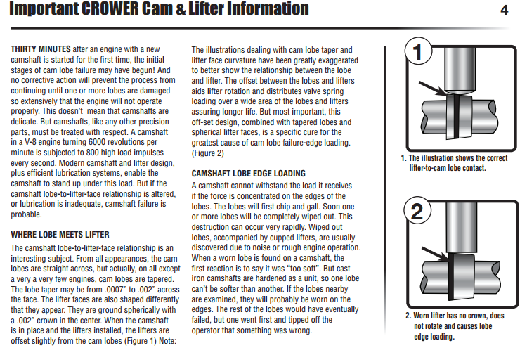
hardface.jpg

lobelif.png

open the link to look at valve spring options
http://www.racingsprings.com/
(866) 799-9417
http://www.racingsprings.com/Staff
heres their ph#
Toll Free (866) 799-9417
I always just order the springs retainers valve locks and spring seats as a package deal (NOT CHEAP BUT EVERYTHING WORKS AND FITS) then you just need shims under the valve spring seats occasionally to get the correct installed height

http://www.racingsprings.com/Valve Springs/Store/13
read ....don,t ignore the links

http://www.superchevy.com/how-to/engines-drivetrain/sucp-0202-rocker-arm-ratio/


http://garage.grumpysperformance.com/index.php?threads/oil-system-mods-that-help.2187/

http://garage.grumpysperformance.co...lifter-to-increase-oil-flow.11152/#post-49968

http://garage.grumpysperformance.com/index.php?threads/magnets.120/

http://garage.grumpysperformance.com/index.php?threads/break-in-oil-quality-tested.11145/#post-52505

http://garage.grumpysperformance.co...ear-articles-you-need-to-read.282/#post-52017


yes its just a fact that most flat tappet cams have far higher percentage of wear issues, as a result, many cam vendors are dropping flat tappet cams and lifters,
simply because the cars that use them are now mostly a very small percentage of the market and most of those engines are over 50 years old, and no longer profitable to service, thus many vendors are just sticking to supplying roller cams and roller lifter's only
 
Last edited:
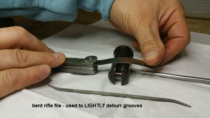
Back
Top