Crazy Port Velocity

Chad Speier

Active Member
So look at this and it almost makes you forget you think something about port speed and localized velocities. I decided to go Super Stock racing. For the last 4 years I have been developing the legal Edelbrock casting with racer help and most importantly FJ Smith. I can talk about all this because it's MY engine.

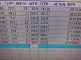
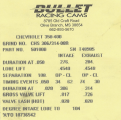
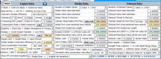
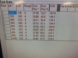
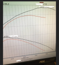
The engine is a 1970 LT1 combo. 350/360hp.. NHRA has it rated at 330. I get the angle plug head and 2.02/1.600. It has 11.5 compression. The heads flow sheet is posted. There IS NOT one area in the port under 400fps. The MIN CSA is 1.80in at the pushrod. The throat is 92%. I have attached the actual dyno sheet and the PipeMax simulation for the Stuska dyno. I'm getting ready to put it back on the dyno with changed.

The question, how does a cylinder head that has a 2.04 AVG CSA, and is 172cc, make the power and at 7100??

I have lots of data I can post up tomorrow.278617215_332951785597315_4860672439211879603_n.jpgchadss.PNGchadfl.jpg
 
Last edited:
first congrats on achieving the head flow numbers those numbers are much better than most.
thank you for posting, it should both help inform a few members and may result in a few head sales.
, and as you obviously are well aware, the closer you get to a true round or circular port shape, and filling the port floor to increase the port center of flow mass with the epoxy filler, allows the lower the percentage of surface area on the port walls for a given port volume, you can achieve and the higher the percentage of the port cross sectional area calculate port stalls not directly adjacent to the port walls, thus potentially slowing port flow.
images

A useful tool for calculating the power potential of most cylinder heads is the following formula HP=. 257 x (peak) airflow x number of cylinders.
If we plug in flow data from a typical CNC-ported small-block cylinder head that offered a peak flow of 304 cfm, we get the following: HP=. 257 x 304 x 8 or 625 hp.

index.php

 
Last edited:
I have actually found flow and it staying attached longer in these smaller ports by introducing turbulence into the port.
 
Thanks for sharing Chad!

What were you trying to gain from the PipeMax simulation? Have you feed the actual dyno numbers back into PipeMax to help with the header configuration?

Larry Meux is quick to comment when someone posts on his forum.
.
 
Thanks for sharing Chad!

What were you trying to gain from the PipeMax simulation? Have you feed the actual dyno numbers back into PipeMax to help with the header configuration?

Larry Meux is quick to comment when someone posts on his forum.
.

Yes header, collectors, carburetor, and last cam.

The cam is 100% wrong. Way too much overlap, too much duration, something from 2005 IMO. The Edelbrock heads are 20 cfm better from .500 up. I think Bullet missed it by a mile so I have a new cam on the way.
 
I have Dynomation 6 and PipeMax 4.70 if you are interested in doing some simulations ?
What version of PipeMax did you use ?

How did you measure the length of the port centerline length for input to PipeMax ?

Dynomation has two simulation modes, "Full Wave Action (FWA)" or "Filling/Emptying Wave Assisted (FEWA)". No one has ever had all info needed to do FWA, FEWA is by far the easiest, but the least accurate.

The table below is for FEWA.

Dynomation 6 Input Variables

Bore & Stroke:
Displacement: cubic inches
Rod Length:
Heads Make/Model with flow numbers: Flow (CFM) at several lift points.
Combustion Chamber Size in CC’s:
Piston: For a domed piston use a (-) negative number. For a piston with valve reliefs or dish, use a (+) positive number.
Deck Clearance:
Head Gasket Bore:
Head Gasket Thickness:
Valve Sizes Intake/Exhaust:
Intake Manifold Model Type: [Single or Dual Plane]
Model #:
Carburetor Size or EFI (CFM):
Blower/Turbo Make/Model:
Belt Ratio:
SCR & DCR: Or the info to calculate SCR & DCR [ http://garage.grumpysperformance.co...comp-ratio-cranking-pressure-calculator.4458/ ]
Header Tube Diameter: Small, Medium, Large (1-5/8", or , or)
Cam Card: I Need all 8 valve timing events at seat-to-seat and at 0.050” + lobe lift or valve lift, Advance or Retard from Split Overlap.
Rocker Ratio - Intake/Exhaust:
Cam Installed per Cam Card, or Retarded or Advanced:
Fuel Used: Gasoline, Methanol, Ethanol, E85 .....

More questions most likely to follow ......
.
 
I have Pipemax 4.70 as well. I will fill all that info above out tomorrow morning and let you run dynomation!
 
The recommended way to measure port centerline length by LarryM is using 1/8 inch tape along both the short side and long side of the port, remove the tape and place it in a straight line to be measured. Shown in the first 4 photos below. Be careful not to stretch the tape, it's only 1/8 inch wide.

Chad, I'm thinking you already knew this info. But for the others reading this thread it might be helpful.

FP08_PortRunnerMeasurements01_01593.jpg

FP08_PortRunnerMeasurements02_01597.jpg

FP08_PortRunnerMeasurements03_01599.jpg

FP08_PortRunnerMeasurements04_01603.jpg

To measure the port perimeter/area just hold graph paper up to the port and tap with a hammer along the entry edge.

FP08_PortRunnerMeasurements05_01609.jpg
FP08_PortRunnerMeasurements06_ExcelTable.jpg
 
Last edited:
Bore & Stroke: 4.070 x 3.499
Displacement: cubic inches 363
Rod Length: 5.70- rule
Heads Make/Model with flow numbers: Flow (CFM) at several lift points. I will post flow sheet
Combustion Chamber Size in CC’s: 61.2- rule
Piston: For a domed piston use a (-) negative number. For a piston with valve reliefs or dish, use a (+) positive number. +1.41- rule
Deck Clearance: -.008
Head Gasket Bore: 4.100
Head Gasket Thickness: .040
Valve Sizes Intake/Exhaust: 2.02/1.600- rule
Intake Manifold Model Type: [Single or Dual Plane] Dual
Model #: 2978 Victor E
Carburetor Size or EFI (CFM): 780 VAC SEC- rule
Blower/Turbo Make/Model:
Belt Ratio:
SCR & DCR: Or the info to calculate SCR & DCR [ http://garage.grumpysperformance.co...comp-ratio-cranking-pressure-calculator.4458/ ] 11.5- rule
Header Tube Diameter: Small, Medium, Large (1-5/8", or , or) 1 7/8 - 2"
Cam Card: I Need all 8 valve timing events at seat-to-seat and at 0.050” + lobe lift or valve lift, Advance or Retard from Split Overlap. I will post the cam card
Rocker Ratio - Intake/Exhaust: 1.8/1.60
Cam Installed per Cam Card, or Retarded or Advanced: Advanced 4
Fuel Used: Gasoline, Methanol, Ethanol, E85 .....C12

Flow sheet is .200-1.000
 

Attachments

  • chadfl.jpg
    chadfl.jpg
    368.9 KB · Views: 3
  • cam.PNG
    cam.PNG
    511.1 KB · Views: 4
  • chadss.PNG
    chadss.PNG
    59.6 KB · Views: 4
@Chad Speier

- I only see one flow number and it's not labeled Intake or Exhaust ?

- Are you using a thermal coating on the piston top / combustion chamber or both?

- Dynomation has three race fuel options ....

1665164444071.png 1665164565956.png
1665164625489.png

You will notice the AFR is changing for each selection, but I can override that setting. Or we can get even more detailed by setting an AFR at every 200 rpm.

How would you like to proceed?
Which race gas .... 1, 2 or 3?
Do you want to use the default AFR or override the AFR and what value ? Or use the table ?

1665165175722.png

Below is all I could find on VP's website about C12

1665165817593.png
.
 
The one above is intake, here is exhaust.

No coating.

AFR is in the 14-14.5 range start to finish
 

Attachments

  • 243590586_654682678849140_4075857543311367108_n.jpg
    243590586_654682678849140_4075857543311367108_n.jpg
    331.8 KB · Views: 4
Below is the graph for your simulation. Also included for you to download is a PDF report with all the parameters used in the simulation. Please use it to confirm that I did in fact enter your data correctly, there are many numbers and I try to confirm that I have them right. But it never hurts to have a second set of eyes.


Sim01.jpg

Dynomation can do several things besides just graphing the output .....

Sim01_ProData.jpg

Below is only a sample, since posting all 720° would be quite long. If this is something that you would want to see more of, I would be glad to post the complete info.

Sim01_CrankData_Sample.jpg

Given a goal Dynomation can run several hundred interations and come up what it thinks is the best camshaft parameters. Again, just let me know what interest you.

Do you have another camshaft you want to compare with Sim01 Bullet, that works also !

.
 

Attachments

  • Sim01.pdf
    199.1 KB · Views: 4
I thought it was kinda strange when I saw your intake manifold was a Dual Plane. I have to make certain assumptions when selecting options in Dynomation, so went with the highest flow option in the Dual Plane category. But after running the simulation I started checking out your intake manifold choice (Victor 29785E) and every indication shows it's a single plane. Should I change it ???

 
Last edited:
Yea, I wrote it down wrong. I have a dyno graph from this engine from a Super Flow dyno, I will post up tomorrow. Pretty close to the simulation!
 
I can't find the actual pull with numbers. Here is a screen shot. It made right at 650, it's the red scale.
 

Attachments

  • Capture2.PNG
    Capture2.PNG
    221.8 KB · Views: 2
The reason why two dynos. I purchased the engine complete from a customer. It already had my heads/manifold on it. They changed the rule and allowed angle plug heads. The plug is in a much better location on the angle. I sold off the heads/manifold and put angles on it.

The dyno I use is known for +35 tight. I wasn't worried. I said if it made 610 on the Stuska we were good. It did.
 
Thanks for the explanation about the two dynos, I noticed that the sim was considerably over your first dyno post above. But I usually not too concerned about accuracy, I see simulations as a good way to compare changes to the same engine. It's still nice thou when it does hit the mark!

Getting back to the manifold, I replaced it with a single plane and then compared it to the dual plane.

Sim01_vs_Sim02.jpg

The taper angle of the runner (port) went from 2.5° in the dual plane to 4° in the single plane. When I noticed the difference I played with this some and it really seems to have an affect on the curve.

Do you know what ANGLE your manifold is setup with? 1665245818404.png
 
Back
Top