"do you match the cam to the engine or build the engine to match the cam specs?"
I got asked that question a few days ago, frankly I have never ever considered doing it either way
heres some basics that won,t change theres a couple thousand related threads here to help you.
You may find this a bit different from other forums, as I can assure you I spend about 97% of my time on this site adding links info and valid additional text, where its needed in older threads as I see the need, I don,t think youll find many threads that are 6-8 months old or older that have not had additional sub links or pictures or text added
http://garage.grumpysperformance.com/index.php?threads/semi-fool-proof-cam-sellection.82/
http://garage.grumpysperformance.co...e-springs-and-setting-up-the-valve-train.181/
http://garage.grumpysperformance.com/index.php?threads/dynamic-vs-static-compression.727/
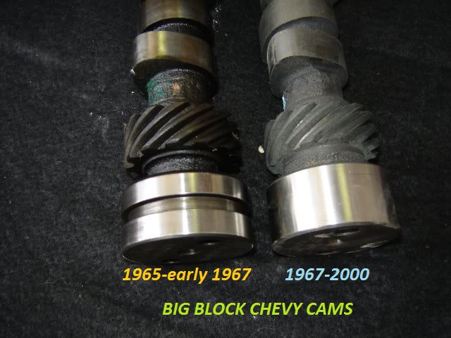
IT helps to know exactly what year and casting number your engine block is as early production big block engines used a different rear cam bearing and cam, a potential rear cam bearing oil flow issue is found on the 1965- too a few very early 1967 engines ,if you install the older design BBC cam with a grooved rear main in EITHER config with EITHER rear bearing your covered, and since thats just not expensive and any decent machine shop can modify any cam like that cheaply is the smart route to take if your in doubt. obviously having the machine
shop groove the rear cam journal under the cam bearing in the block like the later BBC engines would be ideal.
Btw heres a tip learned through experience , if your 496 -540 displacement BBC combo includes an engine with at least 10:1 compression and a cam with at least 240 duration at .050 lift, and oval port heads, youll almost always find a single plane intake has some advantages over a dual plane intake.
https://www.holley.com/products/intakes/single_plane_manifolds/parts/7620
![7620_2[583x].jpg](/proxy.php?image=http%3A%2F%2Fwww.grumpysperformance.com%2Fjuly2017%2F7620_2%5B583x%5D.jpg&hash=5931892943d24f9505466692c10aa541)
http://www.engineersedge.com/lubrication/molybdenum_disulfide_characteristics.htm
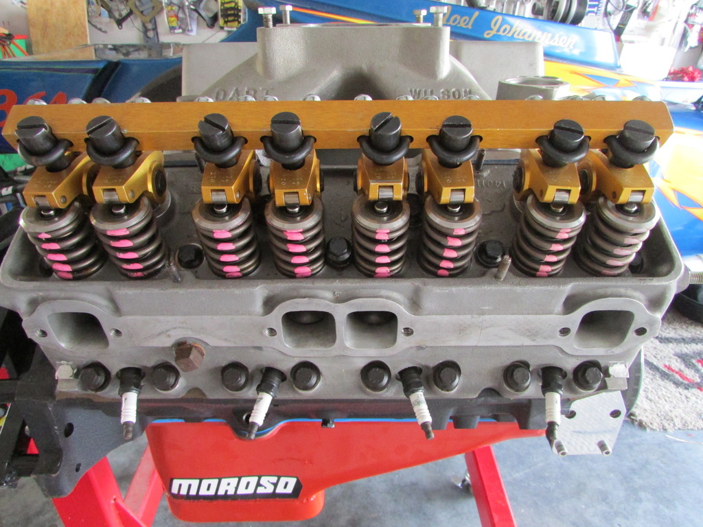
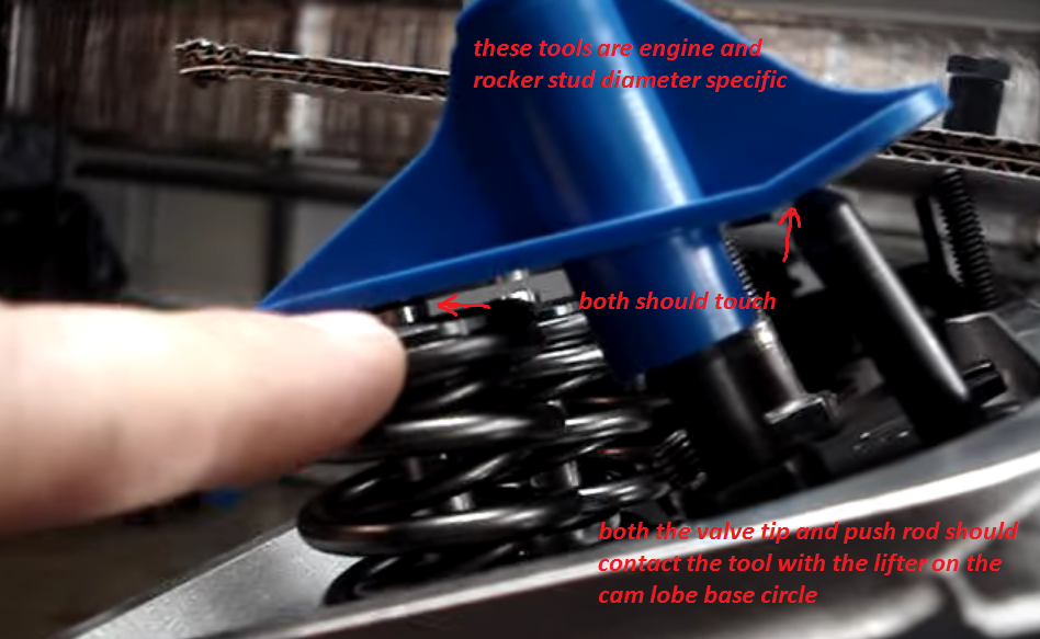
Verifying your engines clearances, and rocker geometry, and use of A rocker stud girdle and high quality roller rockers go a long way towards maintaining valve train durability
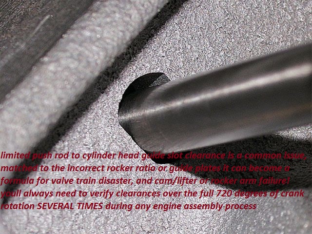
first CHEVK CLEARANCES AND GEOMETRY
the higher rocker ratio increases the effective acceleration rate of the cams lobe ramp, being transmitted to the valve so the higher ratio tends to cause valve control issues at a lower rpm level UNLESS the valve spring load rates increased to compensate. this allows a greater area of lift or open port area so the engine will tend to run better in the mid rpm range, generally making it well worth while as the mile duration cam can use the extra lift and duration at the valve.
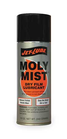
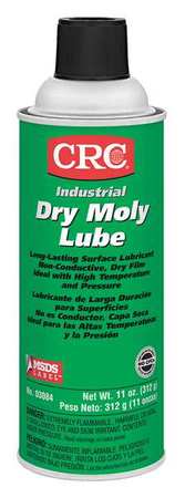
when assembling any engines valve train component parts and bearing surfaces,should be carefully cleaned and soaked with moly spray and then coated with moly assembly lube prior to assembly, Moly exists as microscopic hexagonal crystal platelets Several molecules make up one of these platelets. A single molecule of Moly contains two sulfur atoms and one molybdenum atom. Moly platelets are attracted to metal surfaces. This attraction and the force of moving engine parts rubbing across one another provide the necessary thermochemical reaction necessary for Moly to form an overlapping protective coating like armor on all of your engine parts. This protective armor coating has a number of properties that are very beneficial for your engine.

The Moly platelets that make up the protective layers on your engine surfaces slide across one another very easily. Instead of metal rubbing against metal, you have Moly platelets moving across one another protecting and lubricating the metal engine parts.
This coating effectively fills in the microscopic pores that cover the surface of all engine parts, making them smoother. This feature is important in providing an effective seal on the combustion chamber. By filling in the craters and pores Moly improves this seal allowing for more efficient combustion and engine performance.

This overlapping coating of Moly also gives protection against loading (perpendicular) forces. These forces occur on the bearings, and lifters. The high pressures that occur between these moving parts tend to squeeze normal lubricants out.

http://garage.grumpysperformance.com/index.php?threads/cam-bearing-install-tools-install-info.1479/
Chevy V8 bore & stroke chart
CID BORE STROKE
262 = 3.671" x 3.10" (Gen. I, 5.7" rod)
265 = 3.750" x 3.00" ('55-'57 Gen.I, 5.7" rod)
265 = 3.750" x 3.00" ('94-'96 Gen.II, 4.3 liter V-8 "L99", 5.94" rod)
267 = 3.500" x 3.48" (Gen.I, 5.7" rod)
283 = 3.875" x 3.00" (Gen.I, 5.7" rod)
293 = 3.779" x 3.27" ('99-later, Gen.III, "LR4" 4.8 Liter Vortec, 6.278" rod)
302 = 4.000" x 3.00" (Gen.I, 5.7" rod)
305 = 3.736" x 3.48" (Gen.I, 5.7" rod)
307 = 3.875" x 3.25" (Gen.I, 5.7" rod)
325 = 3.779" x 3.622" ('99-later, Gen.III, "LM7", "LS4 front wheel drive V-8" 5.3 Liter Vortec, 6.098" rod)
327 = 4.000" x 3.25" (Gen.I, 5.7" rod)
345 = 3.893" x 3.622" ('97-later, Gen.III, "LS1", 6.098" rod)
350 = 4.000" x 3.48" (Gen.I, 5.7" rod)
350 = 4.000" x 3.48" ('96-'01, Gen. I, Vortec, 5.7" rod)
350 = 3.900" x 3.66" ('89-'95, "LT5", in "ZR1" Corvette 32-valve DOHC, 5.74" rod)
364 = 4.000" x 3.622" ('99-later, Gen.III, "LS2", "LQ4" 6.0 Liter Vortec, 6.098" rod)
376 = 4.065" x 3.622" (2007-later, Gen. IV, "L92", Cadillac Escalade, GMC Yukon)
383 = 4.000" x 3.80" ('00, "HT 383", Gen.I truck crate motor, 5.7" rod)
400 = 4.125" x 3.75" (Gen.I, 5.565" rod)
427 = 4.125" x 4.00" (2006 Gen.IV, LS7 SBC, titanium rods)
Two common, non-factory smallblock combinations:
377 = 4.155" x 3.48" (5.7" or 6.00" rod)
400 block and a 350 crank with "spacer" main bearings
383 = 4.030" x 3.75" (5.565" or 5.7" or 6.0" rod)
350 block and a 400 crank, main bearing crank journals
cut to 350 size
ALL production big blocks used a 6.135" length rod.
CHEVY BIG BLOCK V-8 BORE AND STROKE
366T = 3.935" x 3.76"
396 = 4.096" x 3.76"
402 = 4.125" x 3.76"
427 = 4.250" x 3.76"
427T = 4.250" x 3.76"
454 = 4.250" x 4.00"
477= 4.5" bore x 3.76" stroke
496 = 4.250" x 4.37" (2001 Vortec 8100, 8.1 liter)
502 = 4.466" x 4.00"
557T= 4.5 bore 4.375" stroke
572T = 4.560" x 4.375" (2003 "ZZ572" crate motors)
T = Tall Deck
ALL production big blocks used a 6.135" length rod.
http://garage.grumpysperformance.co...k-after-a-cam-lobe-rod-or-bearings-fail.2919/
http://garage.grumpysperformance.com/index.php?threads/cam-wear-articles-you-need-to-read.282/
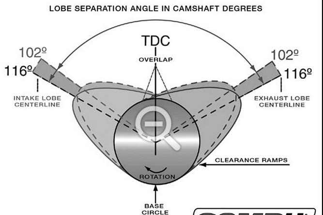
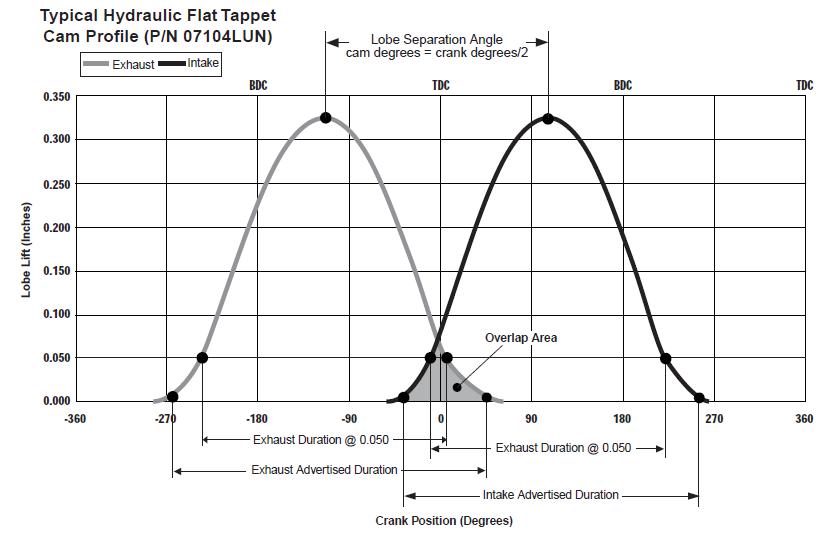
http://www.compcams.com/Pages/413/cam-timing-lobe-separation-angle.aspx
with an engineering back ground Id grab a long legal pad of lined paper and a decent ball point pen, and pocket calculator,

 and list the intended power (IE torque & ,rpm required & limitations) the cars weight drive train or modifications to that drive train, the realistic financial budget and time frame, available resources I have to work with, personnel assets, tools available.
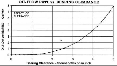
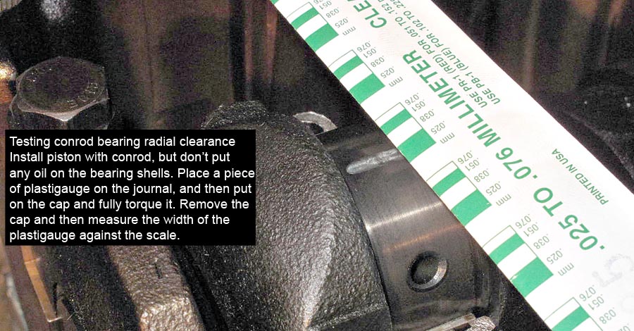
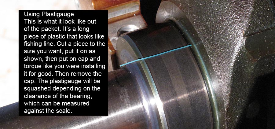
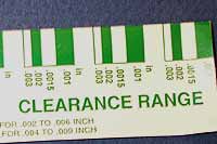
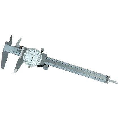
Id realize that the less time wasted in return wasted trips to the local machine shop or reordering parts I forgot to order like bearings fasteners or sealants, gaskets or lubricants, were all going to slow up the process of completing the engine assembly, and that some times just not checking a clearance can cost you several days time so its well worth the cost to buy your own precision measuring tools, its also not mandatory to buy the very best and most accurate and expensive tools available and you can do a remarkably good job with a decent dial caliper and plasti-gauge, if thats all you have available
http://garage.grumpysperformance.com/index.php?threads/bare-minimum-tools.11026/#post-48766
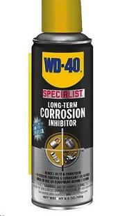
PAINTING THE non-machined surfaces and coating the machined surfaces with a good anti-rust coating like wd40 specialist helps
http://garage.grumpysperformance.com/index.php?threads/storing-an-engine-block.12262/#post-60147
KEEP IN MIND THERES SEVERAL VERSIONS OF WD40 SPECIALIST
YOU WANT THE LONG TERM CORROSION INHIBITOR
read these threads also and THE SUB LINKS
http://garage.grumpysperformance.co...k-after-a-cam-lobe-rod-or-bearings-fail.2919/
http://garage.grumpysperformance.com/index.php?threads/block-prep.125/
http://garage.grumpysperformance.co...ing-a-383-sbc-combo-planing.12168/#post-58783
http://garage.grumpysperformance.co...gine-to-match-the-cam-specs.11764/#post-55651
http://garage.grumpysperformance.co...ectly-and-get-it-to-last-cam-install-info.90/
http://garage.grumpysperformance.com/index.php?threads/finding-a-machine-shop.321/#post-55314
http://garage.grumpysperformance.com/index.php?threads/383-information-overload.11137/#post-49864
http://garage.grumpysperformance.co...y-in-building-a-good-engine.11682/#post-54682
http://garage.grumpysperformance.co...ing-parts-and-a-logical-plan.7722/#post-51341
http://garage.grumpysperformance.com/index.php?threads/parts-prep-cleaning.6255/#post-51146
While cheat sheets might have frowned upon in your sixth-grade classroom, we strongly encourage them in the garage, shop, or pits. That’s why we’ve put together this list of 13 key performance formulas you should know when building or tuning your street or race vehicle.
ANYTIME YOU GET TOTALLY UNEXPECTED RESULTS,
IN A CALCULATION RETRY IT WITH SEVERAL DIFFERENT.
BUT SIMILAR FORMULAS OR CALCULATOR LINKS try this also
http://www.wallaceracing.com/dynamic-cr.php
http://www.pcengines.com.au/calculators/Calculate%20dynamic%20Comp%20Ratio.htm
http://cochise.uia.net/pkelley2/DynamicCR.html
http://www.steigerperformance.com/products/sp90005.html
https://www.uempistons.com/index.php?main_page=calculators&zenid=1e826335bfac0f356463eabed4958558
http://www.enginebasics.com/Advanced Engine Tuning/Static vs Dynamic.html
http://victorylibrary.com/mopar/cam-tech-c.htm
http://www.race-cars.net/calculators/compression_calculator.html
http://garage.grumpysperformance.com/index.php?threads/a-few-calculator-links.7108/#post-27382
http://www.projectpontiac.com/ppsite15/compression-ratio-calculator
http://www.wallaceracing.com/dynamic-cr.php
http://victorylibrary.com/mopar/cam-tech-c.htm
http://www.rbracing-rsr.com/comprAdvHD.htm
http://performancetrends.com/Compression_Ratio_Calculator_V2.3.htm
http://www.wallaceracing.com/cr_test2.php
http://www.pcengines.com.au/calculators/Calculate dynamic Comp Ratio.htm
http://www.csgnetwork.com/compcalc.html
http://www.diamondracing.net/tools/
https://www.uempistons.com/index.php?main_page=calculators&type=comp
https://www.rbracing-rsr.com/compstaticcalc.html
Racing Carburetor CFM
Racing Carburetor CFM = RPM x Displacement ÷ 3456 x 1.1
Note: Summit Racing also offers this CFM Calculator to make the job easier.
Displacement
Displacement = .7854 x Bore2 x Stroke x Number of Cylinders
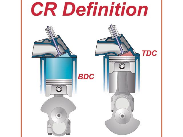
Correct Compression Ratio (CCR)
CCR = FCR (Altitude/1,000) x .2
Note: You can also take this Compression Ratio Calculator tool for a spin.
Tire Diameter
Tire Diameter = (MPH x Gear Ratio x 336) ÷ RPM
Rocker Arm Ratio and Valve Lift
Gross Valve Lift = Camshaft Lobe Lift x Rocker Arm Ratio
Horsepower
Horsepower = (RPM x Torque) ÷ 5,252
Torque
Torque = (5,252 x HP) ÷ RPM
Rod Ratio
Rod Ratio = Rod Length ÷ Crank Stroke Length
Average Piston Speed
Average Piston Speed = Crank Stroke x RPM ÷ 6
Rear Gear Ratio
Rear Gear Ratio = (RPM at Finish Line x Tire Diameter) ÷ (MPH x 336)
Note: You can also save this link to a handy Gear Ratio calculator.
Volume (CCs) of Deck Clearance
CCs of Deck Clearance = Bore x Bore x 12.87 x Depth of Deck Clearance
Volume (CCs) of Head Gasket
CCs of Head Gasket = Bore x Bore x 12.87 x Thickness of Head Gasket

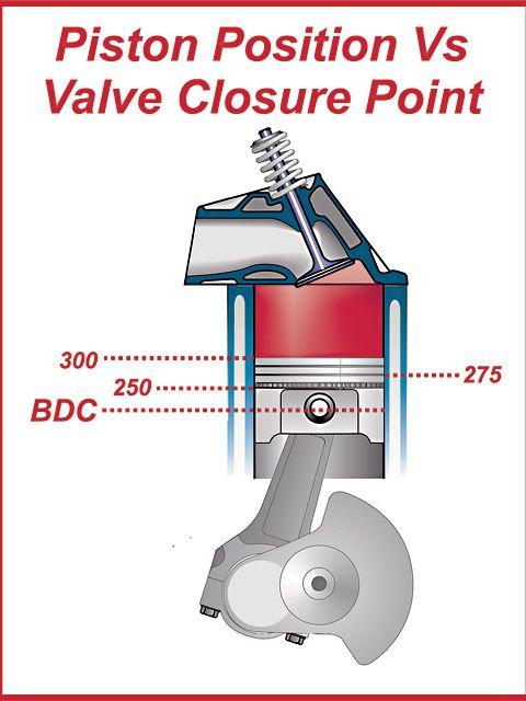
Building an engine around a cam is going to be, a very limited concept,simply, because the idea assumes that a set lift and duration and LCA is maxed out with a perfectly matched set of components, and frankly the math to prove that would be mind bending-ly complex in that a single factor like the temperature of the exhaust gases exiting the exhaust port could change the results, deciding on all the components that will be used on an engine build, by looking at the cam lobe design alone, would be a bit like deciding on the correct gal too marry, based, solely on , looking over her hand selected luggage and her hand selected negligee color alone.
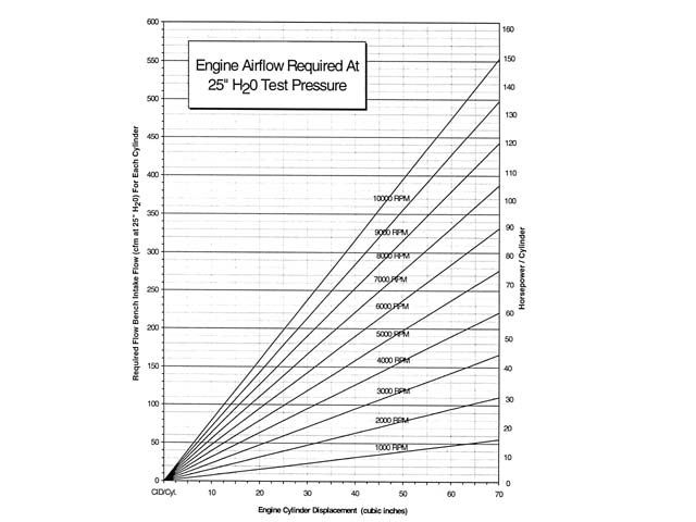
A camshaft is a mechanical device, used to control valve speed acceleration, lift rates for that duration and that in theory controls air flow rates through the cylinders at various rpm rates, It's the cam lobe lift and duration rates matched to the port volume and cylinder displacement, piston size and engines stroke and rod length that determine the way air enters and exits the cylinder, that is designed to optimize that airflow in and out of the cylinder, for a specific application, but the cylinder head design, intake design,exhaust header and several other factors like displacement, compression, fuel/air ratio, ignition advance curve,ignition voltage,combustion chamber shape, exhaust collector design,fuel and its octane and engine rpm all can and will change and effect the results your engine will produce.
frankly I think the logical approach is to ask what the engines to be used for, what the customer currently has to work with, or wants to work with, and what his budget limitations and time frame are.
a properly selected cam will tend to help you compensate for areas where you could not get the best possible flow rates, or to increase or decrease cylinder fill rates over a certain rpm range.
example heres what a change in cam LCA does


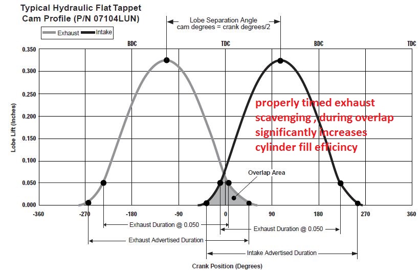
in mind valve lift and port flow limitations[/color]
http://www.wallaceracing.com/runnertorquecalc.php
http://www.wallaceracing.com/ca-calc.php
http://www.wallaceracing.com/area-under-curve.php
http://www.wallaceracing.com/chokepoint.php
http://www.wallaceracing.com/header_length.php
http://www.circletrack.com/enginetech/1 ... ch_engine/
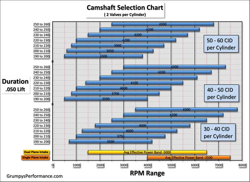
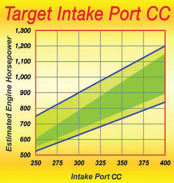
USE THE CALCULATORS to match port size to intended rpm levels... but keep in mind valve lift and port flow limitations[/color]
http://www.wallaceracing.com/runnertorquecalc.php
http://www.wallaceracing.com/ca-calc.php
http://www.wallaceracing.com/area-under-curve.php
http://www.wallaceracing.com/chokepoint.php
http://www.wallaceracing.com/header_length.php
as a general rule you'll find single plane intakes on a SBC generally work best on engine combos with at least a 245 duration cam at .050 lift and with 10.7:1 or higher compression and solid lifter cams that can operate efficiently in the 5500rpm-7000rpm PLUS power band and geared to operate in that same 5500rpm-7000rpm PLUS power band most of the time.
this also requires a short block assembly designed to operate in that upper rpm band, now as the engine displacement is increased, like in the larger displacement BBC engines port and runner air flow speeds will also increase so the effect is that a larger BBC engine can use more, or longer cam duration at a given rpm band, due to its larger cylinder volume to valve curtain area requiring more time, for effective cylinder fill and scavenging .
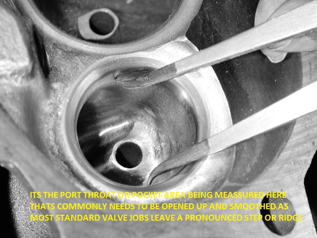
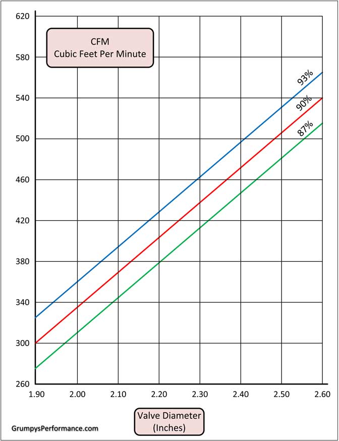
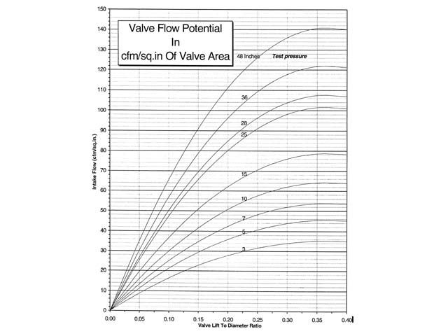
thus a 2.02 valve sbc reaches max flow near .505 lift
thus a 2.19 valve BBC reaches max flow near .5475 lift
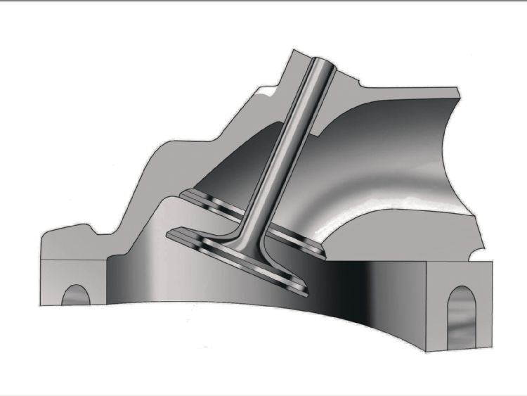
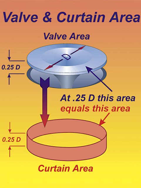
Calculating the valve curtain area
The following equation mathematically defines the available flow area for any given valve diameter and lift value:
Area = valve diameter x 0.98 x 3.14 x valve lift
Where 3.14 = pi (π)
For a typical 2.02-inch intake valve at .500-inch lift, it calculates as follows:
Area = 2.02 x 0.98 x 3.14 x 0.500 = 3.107 square inches
For a typical 2.19-inch intake valve at .550-inch lift, it calculates as follows:
Area = 2.19 x 0.98 x 3.14 x 0.550 = 3.714 square inches
a typical 383 sbc with that .500 lift cam, has 47.875 cubic inches of volume in a single cylinder, divide that by the curtain area of 3.107 and you get 15 cubic inches of cylinder volume for each square inch of valve curtain
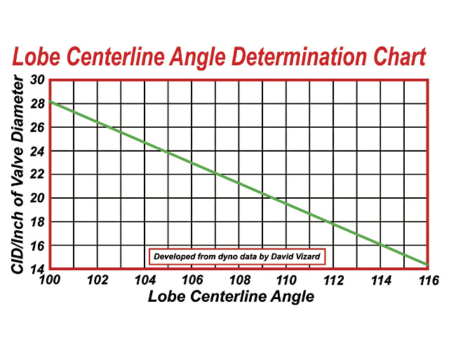
a typical 496 BBC with that .550 lift cam, has 62 cubic inches of volume in a single cylinder, divide that by the curtain area of 3.714 and you get 16.69 cubic inches of cylinder volume for each square inch of valve curtain, or about 11% less available air flow even with the larger valve and higher lift cam, to compensate use of a tighter LCA is frequently used to allow a longer, and more effective cylinder scavenging time frame in the big block combo
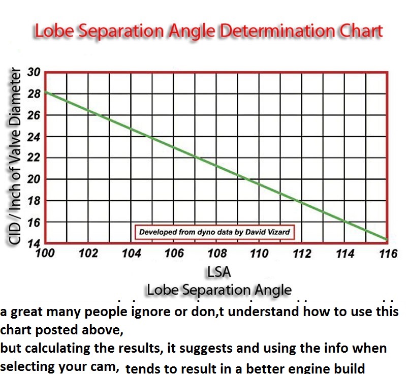

If your designing a performance engine application, you obviously would match the most effective cylinder head port cross sectional area, valve curtain area, valve lift,header design, engine displacement and rpm power band to the cams intended RPM range, engines power band, and GEAR, the cars drive train, so it stays in that operational rpm band the vast majority of its time, while keeping the engine just under the engines critical upper rpm red-line limitations , so its durability is never stressed to the point its life spans compromised, when pushed hard to shift to maximize power.
you would then look at what was available within the budget and logically select the most efficient and cost effective combination of components you could assemble.
you would obviously want to know the car owners experience, what his skill level was, what work he was willing and comfortable doing, and if he had the tools and or a machine shop access locally .
and with experience you learn to avoid chronic weak points in the factory engine design, if the factory connecting rods have an annoying habit of snapping at 6000rpm after a few months youll gain that knowledge through experience , and have long ago swapped to stronger rods, if the factory oil system required a known modification youll have known how to do it .
Keep in mind most guys don,t get past the "lets slap a cam, intake carb, and headers on this car and go racing stage"
I'd bet less than 10% of the guys that claim to be into hot rodding have ever custom built parts like oil pans, or installed a different ring & pinion gear ratio
related links
I'M SIMPLY GIVING YOU INFO SHOULD THE NEED ARISE
YES ITS WORTH READING THROUGH AS EDUCATIONAL INFO
http://garage.grumpysperformance.com/index.php?threads/bits-of-383-info.38/
http://garage.grumpysperformance.com/index.php?threads/tips-on-building-a-383-sbc-stroker.428/
http://garage.grumpysperformance.com/index.php?threads/stroker-tips-by-len-emanuelson.1249/
http://garage.grumpysperformance.com/index.php?threads/more-port-flow-related-info.322/
http://garage.grumpysperformance.com/index.php?threads/block-prep.125/
http://garage.grumpysperformance.com/index.php?threads/engine-block-cylinder-wall-thickness.976/
http://garage.grumpysperformance.co...ty-thats-key-in-building-a-good-engine.11682/
http://garage.grumpysperformance.com/index.php?threads/checking-piston-to-valve-clearances.399/
http://garage.grumpysperformance.co...lding-a-350-or-upgrading-too-a-383-sbc.11408/
http://garage.grumpysperformance.co...g-and-installing-connecting-rods-pistons.247/
http://garage.grumpysperformance.com/index.php?threads/checking-piston-to-valve-clearances.399/
http://garage.grumpysperformance.co...tion-of-crank-durring-short-blk-assembly.852/
http://garage.grumpysperformance.co...ould-you-build-a-350-or-a-383-sbc-combo.8310/
http://garage.grumpysperformance.com/index.php?threads/rods-that-don-t-destroy-your-budget.10958/
http://garage.grumpysperformance.co...ectly-and-get-it-to-last-cam-install-info.90/
http://garage.grumpysperformance.com/index.php?threads/350-383-rebuild.11115/
http://garage.grumpysperformance.co...ing-parts-and-a-logical-plan.7722/#post-68651
http://garage.grumpysperformance.com/index.php?threads/upgrade-choices.11416/
http://garage.grumpysperformance.com/index.php?threads/finding-a-machine-shop.321/
http://garage.grumpysperformance.co...e-springs-and-setting-up-the-valve-train.181/
http://garage.grumpysperformance.com/index.php?threads/oil-system-mods-that-help.2187/
http://garage.grumpysperformance.co...l-pumps-pressure-bye-pass-circuit-works.3536/
http://garage.grumpysperformance.com/index.php?threads/matching-parts-and-a-logical-plan.7722/
http://garage.grumpysperformance.com/index.php?threads/precision-measuring-tools.1390/#post-52469
http://garage.grumpysperformance.com/index.php?threads/what-to-look-for-in-a-good-engine-combo.9930/
http://garage.grumpysperformance.com/index.php?threads/bits-of-383-info.38/
I got asked that question a few days ago, frankly I have never ever considered doing it either way
heres some basics that won,t change theres a couple thousand related threads here to help you.
You may find this a bit different from other forums, as I can assure you I spend about 97% of my time on this site adding links info and valid additional text, where its needed in older threads as I see the need, I don,t think youll find many threads that are 6-8 months old or older that have not had additional sub links or pictures or text added
http://garage.grumpysperformance.com/index.php?threads/semi-fool-proof-cam-sellection.82/
http://garage.grumpysperformance.co...e-springs-and-setting-up-the-valve-train.181/
http://garage.grumpysperformance.com/index.php?threads/dynamic-vs-static-compression.727/
IT helps to know exactly what year and casting number your engine block is as early production big block engines used a different rear cam bearing and cam, a potential rear cam bearing oil flow issue is found on the 1965- too a few very early 1967 engines ,if you install the older design BBC cam with a grooved rear main in EITHER config with EITHER rear bearing your covered, and since thats just not expensive and any decent machine shop can modify any cam like that cheaply is the smart route to take if your in doubt. obviously having the machine
shop groove the rear cam journal under the cam bearing in the block like the later BBC engines would be ideal.
Btw heres a tip learned through experience , if your 496 -540 displacement BBC combo includes an engine with at least 10:1 compression and a cam with at least 240 duration at .050 lift, and oval port heads, youll almost always find a single plane intake has some advantages over a dual plane intake.
https://www.holley.com/products/intakes/single_plane_manifolds/parts/7620
http://www.engineersedge.com/lubrication/molybdenum_disulfide_characteristics.htm
Verifying your engines clearances, and rocker geometry, and use of A rocker stud girdle and high quality roller rockers go a long way towards maintaining valve train durability
first CHEVK CLEARANCES AND GEOMETRY
the higher rocker ratio increases the effective acceleration rate of the cams lobe ramp, being transmitted to the valve so the higher ratio tends to cause valve control issues at a lower rpm level UNLESS the valve spring load rates increased to compensate. this allows a greater area of lift or open port area so the engine will tend to run better in the mid rpm range, generally making it well worth while as the mile duration cam can use the extra lift and duration at the valve.
when assembling any engines valve train component parts and bearing surfaces,should be carefully cleaned and soaked with moly spray and then coated with moly assembly lube prior to assembly, Moly exists as microscopic hexagonal crystal platelets Several molecules make up one of these platelets. A single molecule of Moly contains two sulfur atoms and one molybdenum atom. Moly platelets are attracted to metal surfaces. This attraction and the force of moving engine parts rubbing across one another provide the necessary thermochemical reaction necessary for Moly to form an overlapping protective coating like armor on all of your engine parts. This protective armor coating has a number of properties that are very beneficial for your engine.
The Moly platelets that make up the protective layers on your engine surfaces slide across one another very easily. Instead of metal rubbing against metal, you have Moly platelets moving across one another protecting and lubricating the metal engine parts.
This coating effectively fills in the microscopic pores that cover the surface of all engine parts, making them smoother. This feature is important in providing an effective seal on the combustion chamber. By filling in the craters and pores Moly improves this seal allowing for more efficient combustion and engine performance.
This overlapping coating of Moly also gives protection against loading (perpendicular) forces. These forces occur on the bearings, and lifters. The high pressures that occur between these moving parts tend to squeeze normal lubricants out.
http://garage.grumpysperformance.com/index.php?threads/cam-bearing-install-tools-install-info.1479/
Chevy V8 bore & stroke chart
CID BORE STROKE
262 = 3.671" x 3.10" (Gen. I, 5.7" rod)
265 = 3.750" x 3.00" ('55-'57 Gen.I, 5.7" rod)
265 = 3.750" x 3.00" ('94-'96 Gen.II, 4.3 liter V-8 "L99", 5.94" rod)
267 = 3.500" x 3.48" (Gen.I, 5.7" rod)
283 = 3.875" x 3.00" (Gen.I, 5.7" rod)
293 = 3.779" x 3.27" ('99-later, Gen.III, "LR4" 4.8 Liter Vortec, 6.278" rod)
302 = 4.000" x 3.00" (Gen.I, 5.7" rod)
305 = 3.736" x 3.48" (Gen.I, 5.7" rod)
307 = 3.875" x 3.25" (Gen.I, 5.7" rod)
325 = 3.779" x 3.622" ('99-later, Gen.III, "LM7", "LS4 front wheel drive V-8" 5.3 Liter Vortec, 6.098" rod)
327 = 4.000" x 3.25" (Gen.I, 5.7" rod)
345 = 3.893" x 3.622" ('97-later, Gen.III, "LS1", 6.098" rod)
350 = 4.000" x 3.48" (Gen.I, 5.7" rod)
350 = 4.000" x 3.48" ('96-'01, Gen. I, Vortec, 5.7" rod)
350 = 3.900" x 3.66" ('89-'95, "LT5", in "ZR1" Corvette 32-valve DOHC, 5.74" rod)
364 = 4.000" x 3.622" ('99-later, Gen.III, "LS2", "LQ4" 6.0 Liter Vortec, 6.098" rod)
376 = 4.065" x 3.622" (2007-later, Gen. IV, "L92", Cadillac Escalade, GMC Yukon)
383 = 4.000" x 3.80" ('00, "HT 383", Gen.I truck crate motor, 5.7" rod)
400 = 4.125" x 3.75" (Gen.I, 5.565" rod)
427 = 4.125" x 4.00" (2006 Gen.IV, LS7 SBC, titanium rods)
Two common, non-factory smallblock combinations:
377 = 4.155" x 3.48" (5.7" or 6.00" rod)
400 block and a 350 crank with "spacer" main bearings
383 = 4.030" x 3.75" (5.565" or 5.7" or 6.0" rod)
350 block and a 400 crank, main bearing crank journals
cut to 350 size
ALL production big blocks used a 6.135" length rod.
CHEVY BIG BLOCK V-8 BORE AND STROKE
366T = 3.935" x 3.76"
396 = 4.096" x 3.76"
402 = 4.125" x 3.76"
427 = 4.250" x 3.76"
427T = 4.250" x 3.76"
454 = 4.250" x 4.00"
477= 4.5" bore x 3.76" stroke
496 = 4.250" x 4.37" (2001 Vortec 8100, 8.1 liter)
502 = 4.466" x 4.00"
557T= 4.5 bore 4.375" stroke
572T = 4.560" x 4.375" (2003 "ZZ572" crate motors)
T = Tall Deck
ALL production big blocks used a 6.135" length rod.
http://garage.grumpysperformance.co...k-after-a-cam-lobe-rod-or-bearings-fail.2919/
http://garage.grumpysperformance.com/index.php?threads/cam-wear-articles-you-need-to-read.282/
http://www.compcams.com/Pages/413/cam-timing-lobe-separation-angle.aspx
with an engineering back ground Id grab a long legal pad of lined paper and a decent ball point pen, and pocket calculator,
Id realize that the less time wasted in return wasted trips to the local machine shop or reordering parts I forgot to order like bearings fasteners or sealants, gaskets or lubricants, were all going to slow up the process of completing the engine assembly, and that some times just not checking a clearance can cost you several days time so its well worth the cost to buy your own precision measuring tools, its also not mandatory to buy the very best and most accurate and expensive tools available and you can do a remarkably good job with a decent dial caliper and plasti-gauge, if thats all you have available
http://garage.grumpysperformance.com/index.php?threads/bare-minimum-tools.11026/#post-48766
PAINTING THE non-machined surfaces and coating the machined surfaces with a good anti-rust coating like wd40 specialist helps
http://garage.grumpysperformance.com/index.php?threads/storing-an-engine-block.12262/#post-60147
KEEP IN MIND THERES SEVERAL VERSIONS OF WD40 SPECIALIST
YOU WANT THE LONG TERM CORROSION INHIBITOR
read these threads also and THE SUB LINKS
http://garage.grumpysperformance.co...k-after-a-cam-lobe-rod-or-bearings-fail.2919/
http://garage.grumpysperformance.com/index.php?threads/block-prep.125/
http://garage.grumpysperformance.co...ing-a-383-sbc-combo-planing.12168/#post-58783
http://garage.grumpysperformance.co...gine-to-match-the-cam-specs.11764/#post-55651
http://garage.grumpysperformance.co...ectly-and-get-it-to-last-cam-install-info.90/
http://garage.grumpysperformance.com/index.php?threads/finding-a-machine-shop.321/#post-55314
http://garage.grumpysperformance.com/index.php?threads/383-information-overload.11137/#post-49864
http://garage.grumpysperformance.co...y-in-building-a-good-engine.11682/#post-54682
http://garage.grumpysperformance.co...ing-parts-and-a-logical-plan.7722/#post-51341
http://garage.grumpysperformance.com/index.php?threads/parts-prep-cleaning.6255/#post-51146
While cheat sheets might have frowned upon in your sixth-grade classroom, we strongly encourage them in the garage, shop, or pits. That’s why we’ve put together this list of 13 key performance formulas you should know when building or tuning your street or race vehicle.
ANYTIME YOU GET TOTALLY UNEXPECTED RESULTS,
IN A CALCULATION RETRY IT WITH SEVERAL DIFFERENT.
BUT SIMILAR FORMULAS OR CALCULATOR LINKS try this also
http://www.wallaceracing.com/dynamic-cr.php
http://www.pcengines.com.au/calculators/Calculate%20dynamic%20Comp%20Ratio.htm
http://cochise.uia.net/pkelley2/DynamicCR.html
http://www.steigerperformance.com/products/sp90005.html
https://www.uempistons.com/index.php?main_page=calculators&zenid=1e826335bfac0f356463eabed4958558
http://www.enginebasics.com/Advanced Engine Tuning/Static vs Dynamic.html
http://victorylibrary.com/mopar/cam-tech-c.htm
http://www.race-cars.net/calculators/compression_calculator.html
http://garage.grumpysperformance.com/index.php?threads/a-few-calculator-links.7108/#post-27382
http://www.projectpontiac.com/ppsite15/compression-ratio-calculator
http://www.wallaceracing.com/dynamic-cr.php
http://victorylibrary.com/mopar/cam-tech-c.htm
http://www.rbracing-rsr.com/comprAdvHD.htm
http://performancetrends.com/Compression_Ratio_Calculator_V2.3.htm
http://www.wallaceracing.com/cr_test2.php
http://www.pcengines.com.au/calculators/Calculate dynamic Comp Ratio.htm
http://www.csgnetwork.com/compcalc.html
http://www.diamondracing.net/tools/
https://www.uempistons.com/index.php?main_page=calculators&type=comp
https://www.rbracing-rsr.com/compstaticcalc.html
Racing Carburetor CFM
Racing Carburetor CFM = RPM x Displacement ÷ 3456 x 1.1
Note: Summit Racing also offers this CFM Calculator to make the job easier.
Displacement
Displacement = .7854 x Bore2 x Stroke x Number of Cylinders
Correct Compression Ratio (CCR)
CCR = FCR (Altitude/1,000) x .2
Note: You can also take this Compression Ratio Calculator tool for a spin.
Tire Diameter
Tire Diameter = (MPH x Gear Ratio x 336) ÷ RPM
Rocker Arm Ratio and Valve Lift
Gross Valve Lift = Camshaft Lobe Lift x Rocker Arm Ratio
Horsepower
Horsepower = (RPM x Torque) ÷ 5,252
Torque
Torque = (5,252 x HP) ÷ RPM
Rod Ratio
Rod Ratio = Rod Length ÷ Crank Stroke Length
Average Piston Speed
Average Piston Speed = Crank Stroke x RPM ÷ 6
Rear Gear Ratio
Rear Gear Ratio = (RPM at Finish Line x Tire Diameter) ÷ (MPH x 336)
Note: You can also save this link to a handy Gear Ratio calculator.
Volume (CCs) of Deck Clearance
CCs of Deck Clearance = Bore x Bore x 12.87 x Depth of Deck Clearance
Volume (CCs) of Head Gasket
CCs of Head Gasket = Bore x Bore x 12.87 x Thickness of Head Gasket
Building an engine around a cam is going to be, a very limited concept,simply, because the idea assumes that a set lift and duration and LCA is maxed out with a perfectly matched set of components, and frankly the math to prove that would be mind bending-ly complex in that a single factor like the temperature of the exhaust gases exiting the exhaust port could change the results, deciding on all the components that will be used on an engine build, by looking at the cam lobe design alone, would be a bit like deciding on the correct gal too marry, based, solely on , looking over her hand selected luggage and her hand selected negligee color alone.
A camshaft is a mechanical device, used to control valve speed acceleration, lift rates for that duration and that in theory controls air flow rates through the cylinders at various rpm rates, It's the cam lobe lift and duration rates matched to the port volume and cylinder displacement, piston size and engines stroke and rod length that determine the way air enters and exits the cylinder, that is designed to optimize that airflow in and out of the cylinder, for a specific application, but the cylinder head design, intake design,exhaust header and several other factors like displacement, compression, fuel/air ratio, ignition advance curve,ignition voltage,combustion chamber shape, exhaust collector design,fuel and its octane and engine rpm all can and will change and effect the results your engine will produce.
frankly I think the logical approach is to ask what the engines to be used for, what the customer currently has to work with, or wants to work with, and what his budget limitations and time frame are.
a properly selected cam will tend to help you compensate for areas where you could not get the best possible flow rates, or to increase or decrease cylinder fill rates over a certain rpm range.
example heres what a change in cam LCA does
in mind valve lift and port flow limitations[/color]
http://www.wallaceracing.com/runnertorquecalc.php
http://www.wallaceracing.com/ca-calc.php
http://www.wallaceracing.com/area-under-curve.php
http://www.wallaceracing.com/chokepoint.php
http://www.wallaceracing.com/header_length.php
http://www.circletrack.com/enginetech/1 ... ch_engine/
USE THE CALCULATORS to match port size to intended rpm levels... but keep in mind valve lift and port flow limitations[/color]
http://www.wallaceracing.com/runnertorquecalc.php
http://www.wallaceracing.com/ca-calc.php
http://www.wallaceracing.com/area-under-curve.php
http://www.wallaceracing.com/chokepoint.php
http://www.wallaceracing.com/header_length.php
as a general rule you'll find single plane intakes on a SBC generally work best on engine combos with at least a 245 duration cam at .050 lift and with 10.7:1 or higher compression and solid lifter cams that can operate efficiently in the 5500rpm-7000rpm PLUS power band and geared to operate in that same 5500rpm-7000rpm PLUS power band most of the time.
this also requires a short block assembly designed to operate in that upper rpm band, now as the engine displacement is increased, like in the larger displacement BBC engines port and runner air flow speeds will also increase so the effect is that a larger BBC engine can use more, or longer cam duration at a given rpm band, due to its larger cylinder volume to valve curtain area requiring more time, for effective cylinder fill and scavenging .
thus a 2.02 valve sbc reaches max flow near .505 lift
thus a 2.19 valve BBC reaches max flow near .5475 lift
Calculating the valve curtain area
The following equation mathematically defines the available flow area for any given valve diameter and lift value:
Area = valve diameter x 0.98 x 3.14 x valve lift
Where 3.14 = pi (π)
For a typical 2.02-inch intake valve at .500-inch lift, it calculates as follows:
Area = 2.02 x 0.98 x 3.14 x 0.500 = 3.107 square inches
For a typical 2.19-inch intake valve at .550-inch lift, it calculates as follows:
Area = 2.19 x 0.98 x 3.14 x 0.550 = 3.714 square inches
a typical 383 sbc with that .500 lift cam, has 47.875 cubic inches of volume in a single cylinder, divide that by the curtain area of 3.107 and you get 15 cubic inches of cylinder volume for each square inch of valve curtain
a typical 496 BBC with that .550 lift cam, has 62 cubic inches of volume in a single cylinder, divide that by the curtain area of 3.714 and you get 16.69 cubic inches of cylinder volume for each square inch of valve curtain, or about 11% less available air flow even with the larger valve and higher lift cam, to compensate use of a tighter LCA is frequently used to allow a longer, and more effective cylinder scavenging time frame in the big block combo
If your designing a performance engine application, you obviously would match the most effective cylinder head port cross sectional area, valve curtain area, valve lift,header design, engine displacement and rpm power band to the cams intended RPM range, engines power band, and GEAR, the cars drive train, so it stays in that operational rpm band the vast majority of its time, while keeping the engine just under the engines critical upper rpm red-line limitations , so its durability is never stressed to the point its life spans compromised, when pushed hard to shift to maximize power.
you would then look at what was available within the budget and logically select the most efficient and cost effective combination of components you could assemble.
you would obviously want to know the car owners experience, what his skill level was, what work he was willing and comfortable doing, and if he had the tools and or a machine shop access locally .
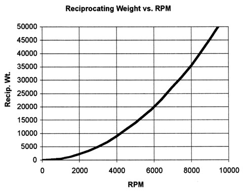
and with experience you learn to avoid chronic weak points in the factory engine design, if the factory connecting rods have an annoying habit of snapping at 6000rpm after a few months youll gain that knowledge through experience , and have long ago swapped to stronger rods, if the factory oil system required a known modification youll have known how to do it .
Keep in mind most guys don,t get past the "lets slap a cam, intake carb, and headers on this car and go racing stage"
I'd bet less than 10% of the guys that claim to be into hot rodding have ever custom built parts like oil pans, or installed a different ring & pinion gear ratio
related links
I'M SIMPLY GIVING YOU INFO SHOULD THE NEED ARISE
YES ITS WORTH READING THROUGH AS EDUCATIONAL INFO
http://garage.grumpysperformance.com/index.php?threads/bits-of-383-info.38/
http://garage.grumpysperformance.com/index.php?threads/tips-on-building-a-383-sbc-stroker.428/
http://garage.grumpysperformance.com/index.php?threads/stroker-tips-by-len-emanuelson.1249/
http://garage.grumpysperformance.com/index.php?threads/more-port-flow-related-info.322/
http://garage.grumpysperformance.com/index.php?threads/block-prep.125/
http://garage.grumpysperformance.com/index.php?threads/engine-block-cylinder-wall-thickness.976/
http://garage.grumpysperformance.co...ty-thats-key-in-building-a-good-engine.11682/
http://garage.grumpysperformance.com/index.php?threads/checking-piston-to-valve-clearances.399/
http://garage.grumpysperformance.co...lding-a-350-or-upgrading-too-a-383-sbc.11408/
http://garage.grumpysperformance.co...g-and-installing-connecting-rods-pistons.247/
http://garage.grumpysperformance.com/index.php?threads/checking-piston-to-valve-clearances.399/
http://garage.grumpysperformance.co...tion-of-crank-durring-short-blk-assembly.852/
http://garage.grumpysperformance.co...ould-you-build-a-350-or-a-383-sbc-combo.8310/
http://garage.grumpysperformance.com/index.php?threads/rods-that-don-t-destroy-your-budget.10958/
http://garage.grumpysperformance.co...ectly-and-get-it-to-last-cam-install-info.90/
http://garage.grumpysperformance.com/index.php?threads/350-383-rebuild.11115/
http://garage.grumpysperformance.co...ing-parts-and-a-logical-plan.7722/#post-68651
http://garage.grumpysperformance.com/index.php?threads/upgrade-choices.11416/
http://garage.grumpysperformance.com/index.php?threads/finding-a-machine-shop.321/
http://garage.grumpysperformance.co...e-springs-and-setting-up-the-valve-train.181/
http://garage.grumpysperformance.com/index.php?threads/oil-system-mods-that-help.2187/
http://garage.grumpysperformance.co...l-pumps-pressure-bye-pass-circuit-works.3536/
http://garage.grumpysperformance.com/index.php?threads/matching-parts-and-a-logical-plan.7722/
http://garage.grumpysperformance.com/index.php?threads/precision-measuring-tools.1390/#post-52469
http://garage.grumpysperformance.com/index.php?threads/what-to-look-for-in-a-good-engine-combo.9930/
http://garage.grumpysperformance.com/index.php?threads/bits-of-383-info.38/
Last edited: