read these thread LINKS and watch this video link below first,
because theres a ton of related info that can help, you ,
to prevent oil & coolant or vacuum leaks, and gasket damage,
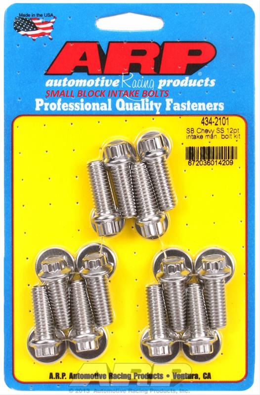
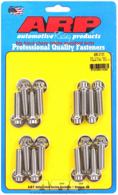
BE AWARE that if the intake manifold bolts used are too short the threads may strip,
\if they are too long you might bend or lock a push rod or.
crack a head casting if overly tightened in the wrong location
viewtopic.php?f=44&t=700
viewtopic.php?f=50&t=1877&p=4937&hilit=propane#p4937
http://garage.grumpysperformance.com/index.php?threads/how-to-pick-timing-gear-set.4548/#post-43700
viewtopic.php?f=44&t=700&p=1095&hilit=sealant#p1095
viewtopic.php?f=80&t=1288&p=24016&hilit=sealant#p24016
viewtopic.php?f=44&t=1430&p=20967&hilit=sealant#p20967
viewtopic.php?f=54&t=3084&p=8194&hilit=sealant#p8194
viewtopic.php?f=54&t=2725&p=7076&hilit=sealant#p7076
viewtopic.php?f=55&t=5378&p=16106&hilit=1206#p16106
viewtopic.php?f=44&t=38&hilit=1206+1205
http://garage.grumpysperformance.co...ei-distributors-ignition-advance-curve.16425/
\\
these gaskets work ok,
http://www.mr-gasket.com/ProductsListBy ... election=6
http://www.summitracing.com/parts/FPP-1205/
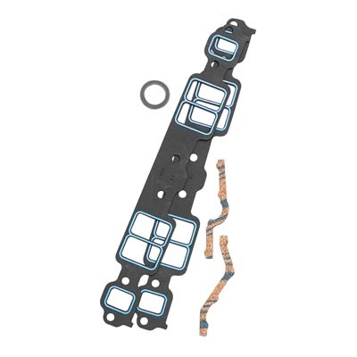
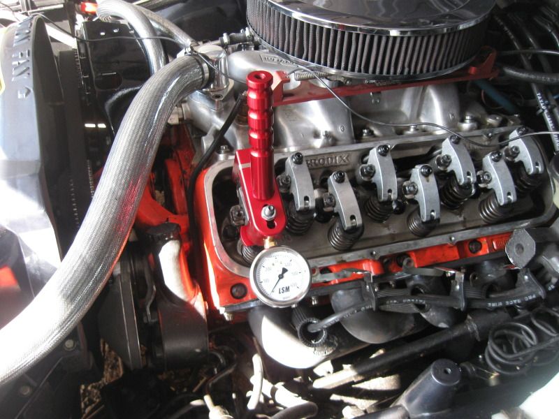
the basic process starts with selecting quality intake gaskets that fit your cylinder heads and intake port size.
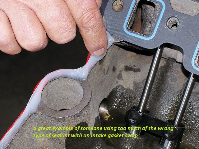
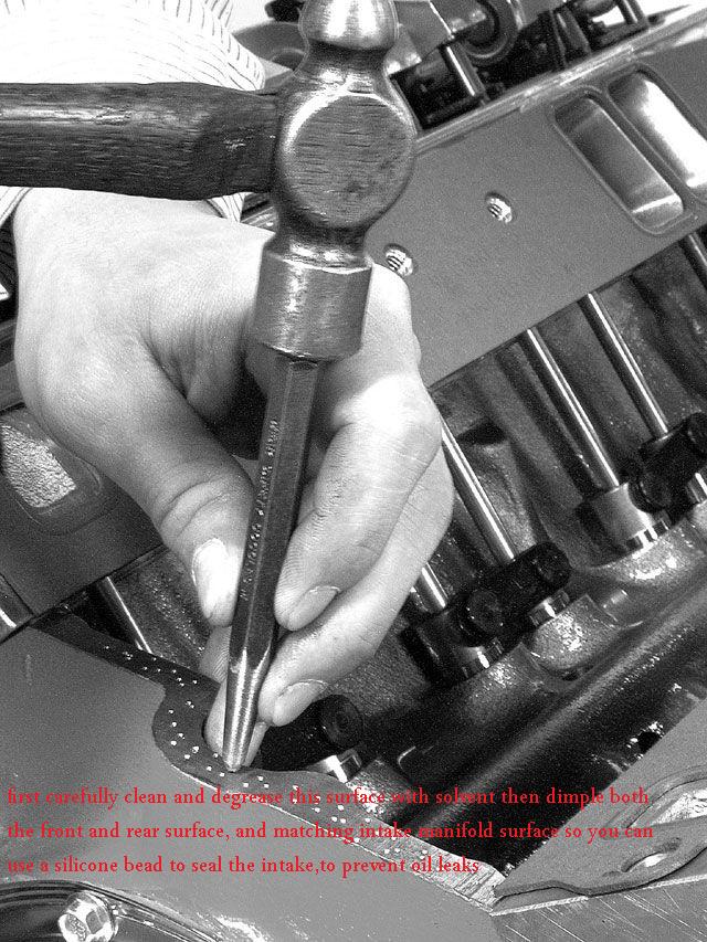
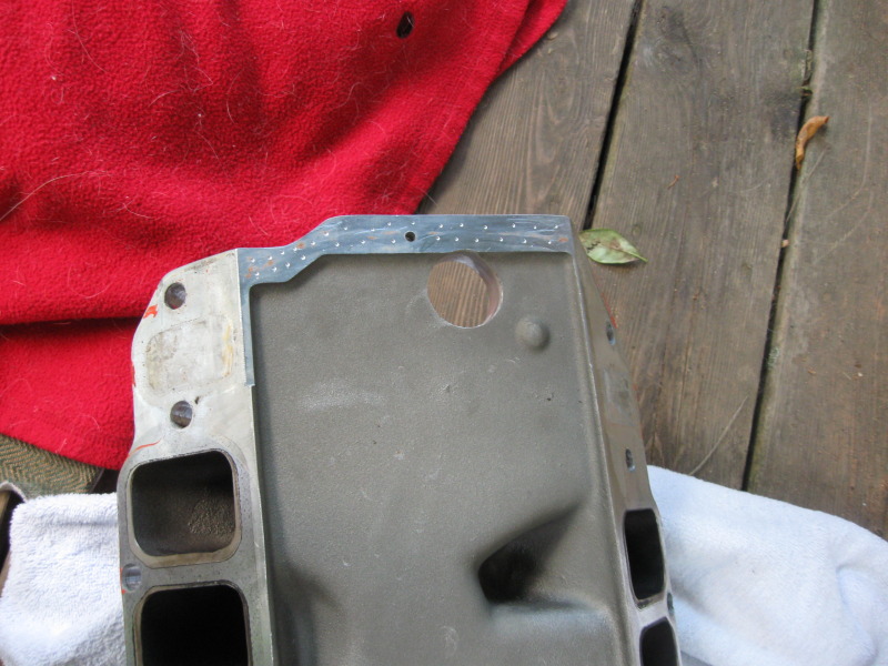
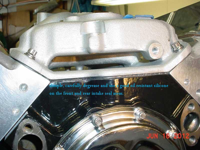
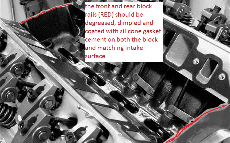
most Chevy intake gaskets seal best if you pitch/throw the end gasket cork or rubber end rail sections in a dumpster and take the time to carefully de-grease, then dimple the upper surface on the blocks front and rear, and matching intake manifold and matching front and rear intake under surface's and use use your finger to smear a thin coat of sealant on both upper and lower surfaces,to insure a good mechanical bond then run or add about a 1/4" bead of silicone gasket cement on both surfaces before you install the intake as the silicone will fill and seal the gap more consistently and the dimple surface gives it a firm grip if properly applied, you can also use a thin bead around the coolant transfer ports and if you really want a good seal, a spray coating of copper coat spray like you might use on head gaskets won,t hurt either, but its generally not a good idea to use much silicone around intake ports as it tends to squeeze out and firm up , leaving a restrictive lip sticking into the intake runner ports if any excess is used.
http://www.nationaltbucketalliance.com/ ... torque.asp
read this thread and sub linked info
viewtopic.php?f=50&t=609
if your worried about intake leaks heres a tip, when your worried about to the front and rear intake manifold seals I don,t think it matters, if the gasket set came with or without block rail seals, that much as they generally get pitched in a local dumpster
watch the video
http://www.youtube.com/watch?v=YdIGZ-tV ... re=related
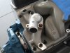
trimming off any excess head gasket tip that protrudes into the seal area with a sharp chisel, and dimpling both the block forward and rear rails and the matching intake surfaces before applying a 1/4" thick bead of sealant to both surfaces help maintain a good oil seal on the intake to block end gaskets on the intake
step 1
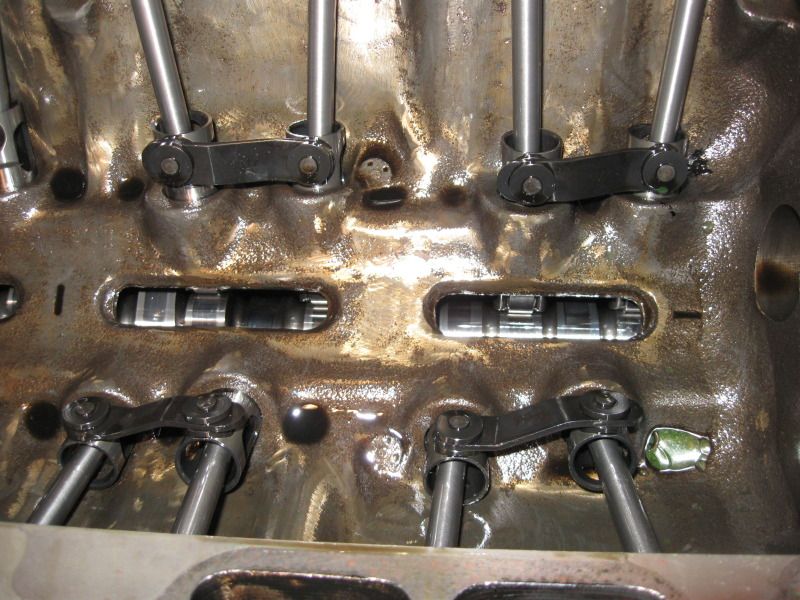
pull and carefully clean and degrease the intake mount surfaces...BUT ONLY after you bring the engine to TDC on the damper tab and balancer marks and verifying the distributor rotor is pointing at cylinder #1, so you know where its suppose to point during the re-installation then
throw the intake manifold kits rubber front and rear intake seal bars in the new intake set in the dumpster
http://www.napaglove.com/products/index ... duct_ID=79
DISPOSABLE GLOVES HELP

step 2
clean the block rails and the matching lower intake surfaces with acetone, or a toluene soaked, shop rag. clean all previous gasket material and sealant off the heads and block surfaces with a gasket scrapper or razor, and acetone soaked rag, (optional but recommended) then use a steel center punch to dimple the block upper surface china walls(front and rear upper surface lightly , and the matching lower intake rail area, to provide a firm grip and adhesion for the high temp silicone gasket cement, youll spread in a 1/4" thick bead on both surfaces, be sure the corners get just a bit extra silicone during the application of the silicone gasket cement
step 3
place a 1/4" wide bead of black silicone sealant along the length of the center of BOTH the front and rear block rails and both the matched lower intake mating surfaces, just AFTER first spreading a bonding coat on both dimpled surfaces with your finger,and allowing it to bond and dry for 2 minutes so the silicone beads that will shortly be added, and melded/compressed above and compressed between the matched dimpled mating surfaces,you just covered with a thin layer of smeared gasket cement and that bead of sealant on those twin mating surfaces of the block rail and intake will bond firmly place the intake port gaskets and align the bolt holes with the holes in the cylinder heads and put a small very thin bead of silicone sealant around 360 degrees of the water transfer ports,on both sides of the gasket, on both gaskets then place the intake straight down into place so the wet sealant beads mesh, blend and squeeze out a bit.
step 4
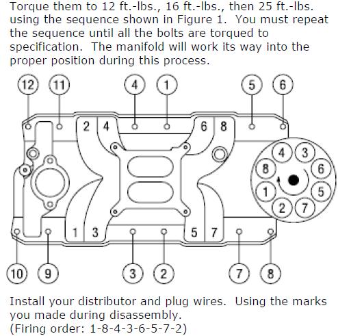
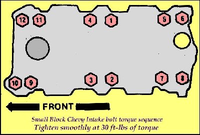
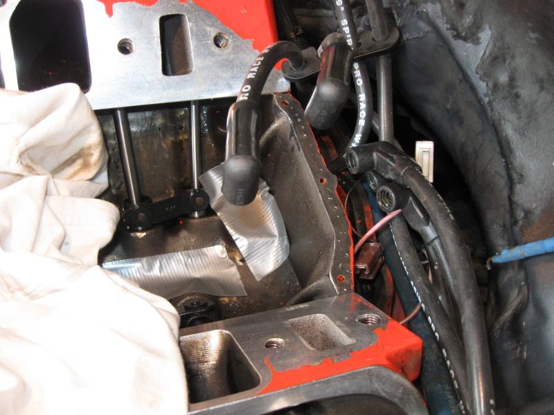
drop the intake into place with minimal forward or backward or side to side movement, use a long Phillips screw driver in a bolt hole will help to easily align the intake, tighten slowly in stages working from the center bolts outward, use a #2 Phillips screw driver to make minor adjustments to the intake thru the bolt holes if it moved a bit during the install, then drop the bolts into place and thread all bolts finger tight before tightening any of them,.then torque them down in stages, working in a circular pattern out to the ends.
http://www.nationaltbucketalliance.com/ ... torque.asp
http://www.summersbrothersracing.co...LF-CUT-DRIVE-FLANGE-BIG-BLOCK-CHEVY_p_30.html
step 5
allow to dry for a couple hours minimum over night,will be better, before use
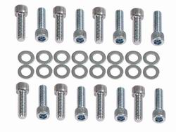
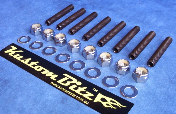
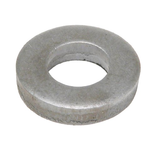
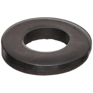
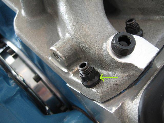
Id consider extending the threads in a hole drilled for the intake mount bolts in aluminum heads to about almost the full depth 1.2" depth the factory drilled the holes in aluminum heads to at least 1" depth after your finished fixing the threads,if you have any stripped thread issues and ID BE using studs with an allen key top to thread into the heads like bolts after the intakes installed so they have full thread engagement before you use a washer and nut to clamp the intake, because doing it that way will almost totally eliminate any possibility of the thread problems in the future, yes it takes a bit longer but it also prevents stripped threads
http://www.boltdepot.com/Product-Detail ... oduct=8567
OPTIONAL but RECOMMENDED
the use a sharp object like a steel punch or awl and plastic hammer to DIMPLE both upper and lower surfaces to give the silicone sealant a firmer grip, by lightly dimpling the surfaces over a large surface realy does increase the bond and tends to avoid leaks
http://www.harborfreight.com/cpi/ctaf/displayitem.taf?Itemnumber=39940
http://www.harborfreight.com/cpi/ctaf/displayitem.taf?Itemnumber=621
btw the correct length , threaded carb STUDS to mount the carb to the intake are far less likely to strip threads in the manifold
look if your only installing a distributor after a manifold swap,and start from scratch on the ignition timing,
ITS not complicated, pull the #1 plug and put you thumb over the hole tightly, turn the engine in the normal direction of rotation, with a breaker bar and socket until you get compression in the #1 cylinder, as the damper TDC line approaches the TDC timing tab, drop the distributor in with the rotor facing the #1 cylinder,compensate for the way the distributor gear causes the rotor to rotate as in seats,so its seated pointing where you intended, if it won,t fully seat turn the oil pump drive with a very large flat blade screw driver until it will,with the distributor removed and try again, once it seats,facing the correct direction, install and tighten the distributor clamp so its difficult to spin the distributor easily by hand but still possible to spin the distributor by hand, re-install the #1 plug and wire, install the cap and all ignition related wires, use your timing light and set the ignition timing,per the shop manuals instructions, tighten the distributor hold clamp so it can,t move, IF it takes more than 10 minutes your in need of more practice or nearly hopeless as a mechanic.The CLOYES true roller style is vastly superior to the factory link belt design
lets drop to basics,
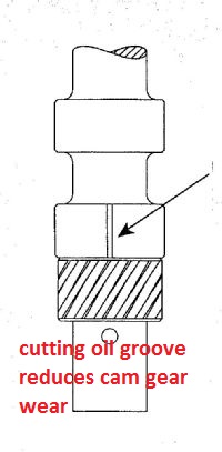
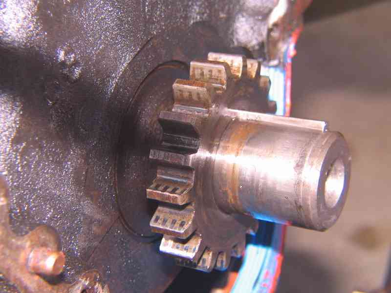
the crank socket has an index groove that matches a key in the crank snout, and you must use the matched set of timing gears (cam and crank) not for example use the new cam gear with the old crank gear for two main reasons, first the old gears have formed a wear pattern, that won,t exactly match the new chain and that tends to accelerate wear on the new chain slightly, and second , different manufacturers tend to mark and index the gears slightly differently, and while in theory both the pin in the cam gear and the woodrif key in the crank gear limit the chances of a mis-match theres occasionally a couple of degrees of difference in mis-matched sets
be aware that some crank gears have more than one index slot to index to the crank key and each slot is marked and you must use the correct matching marks indicating (ZERO) that match the crank slot marks
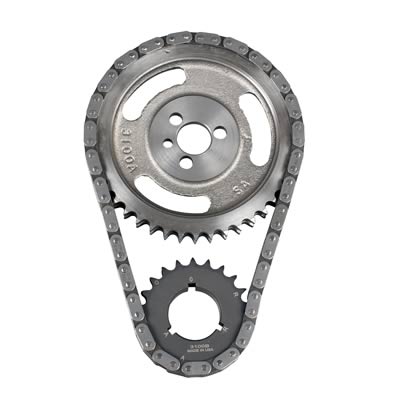
look closely SLOT A uses a different TDC mark (A) than slot (R), which has its own TDC mark(R)
viewtopic.php?f=59&t=901&p=1462&hilit=puller#p1462
most guys oil the crank snout and heat the crank gear slightly and tap it on with a large socket
but yes theres a tool
http://www.summitracing.com/parts/CCA-4789/
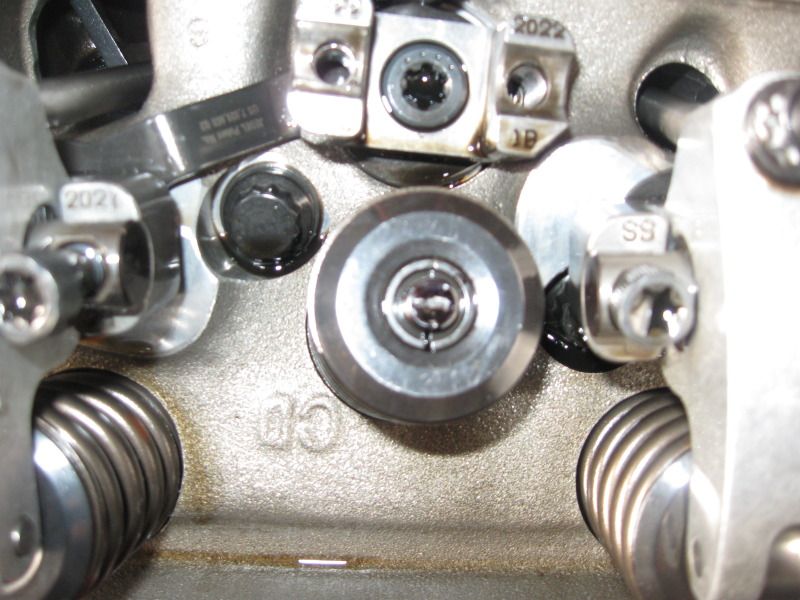
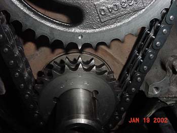
notice the (O) thats supposed to be indexed at 12 o,clock
and matched to a cam timing gear at 6 o,clock, which temporarily places the #6 cylinder at TDC, you then simply rotate the crank one complete turn, bring the cam timing gear to its 12 0,clock position,and the #1 cylinders at TDC and you can drop the intake on, and distributor in and adjust the valve lash clearance (solid lifters) or pre-load (hydraulic lifters, and set the ignition timing at about 8 degrees btdc as a starting location
you can use a dead blow hammer or the damper tool to install the gear
http://www.harborfreight.com/cpi/ctaf/d ... mber=41800
http://www.summitracing.com/parts/OTC-6505/
viewtopic.php?f=52&t=90
read
http://www.centuryperformance.com/tunin ... g-148.html

http://boxwrench.net/specs/chevy_sb.htm

drop the distributor in with the rotor pointing at the #1 cylinder, and YEAH! it physically possible to get the distributors rotor to point at any place you want it too by changing the oil pump drive shaft alignment with a large flat blade screw driver while the distributors out of the engine and that's easily changed, but to do it correctly,you want the rotor to point at the #1 cylinder on the compression stroke, so pull the #1 plug, get a large ratchet/socket on the damper and put your finger over the open plug hole and slowly rotate the engine by hand in its normal rotational direction until you see pressure build under your finger as the rotor approaches #1 cylinder location on the distributor base which you should have marked as its supposed to be in direct alignment between the distributor and the number 1 cylinder on the engine,
remember the distributor and cam gears are helical and the rotor turns as it seats so compensate slightly. and the rotor should be just coming into alignment as pressure builds under your finger, once that's done re-install the distributor cap and plug and use a timing light to set the timing, you normally want about 6-12 degrees BTDC at idle and watch it advance to about 37 degrees as the rpms build to about 3000 rpm ok, then have you checked the distributor to oil pump drive shaft length?,
IF YOUR DISTRIBUTOR LEAKS OIL AROUND THE BASE GASKET..
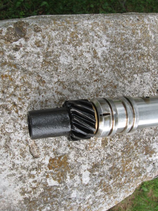
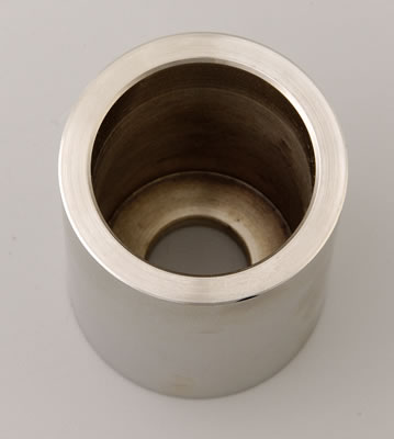
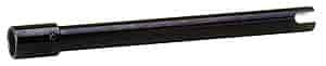
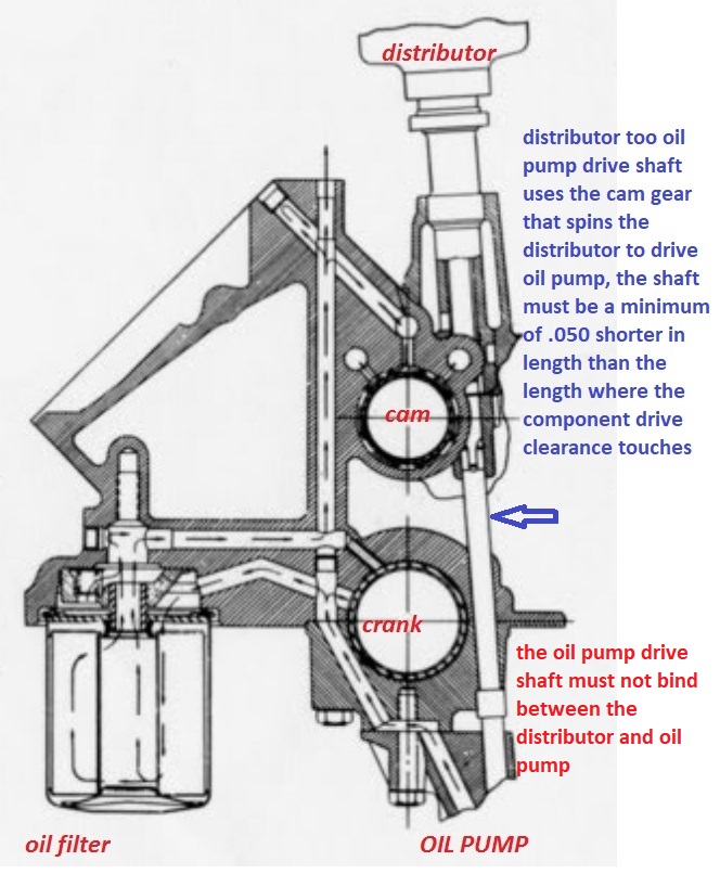
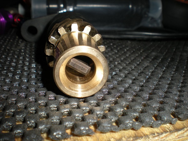
it seems the distributor is not seating fully against the intake ring gasket and the distributor to oil pump drive is suspected of being a bit to long, there should be about .050 slack MINIMUM between the oil pump drive shaft and the distributor gear.
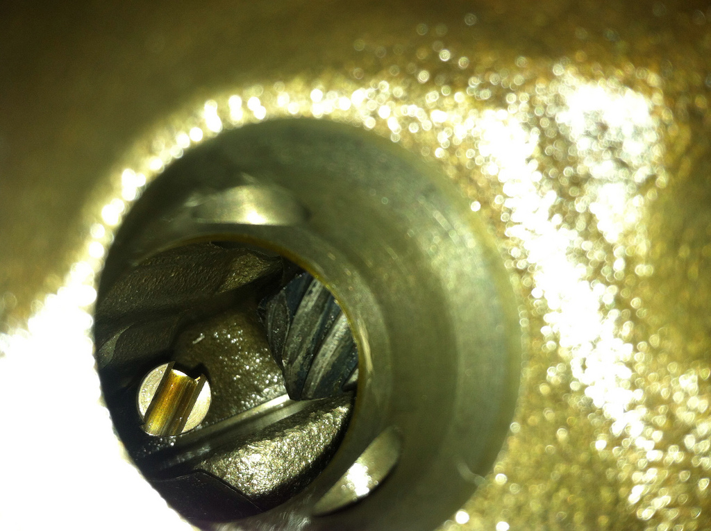
remember the oil pump drive only seats in two locations 180 degrees apart but it can be lined up anyplace you want with a 18" long large flat blade screw driver prior to installing the distributor from the top of the engine rather easily before you re-seat the distributor, but as the distributor gear teeth mesh the distributor will turn the rotor about 15 degrees
viewtopic.php?f=52&t=196
http://garage.grumpysperformance.com/index.php?threads/oil-pan-gaskets.206/#post-390
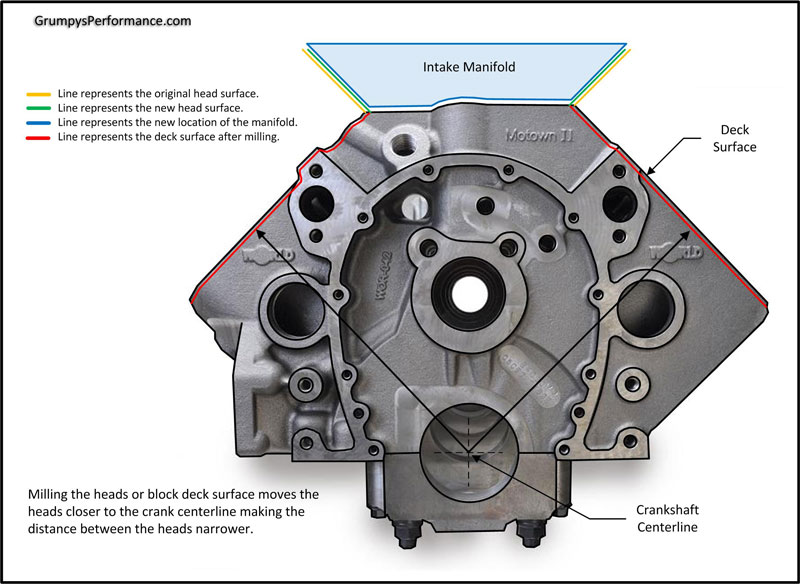
to prevent oil & coolant or vacuum leaks, and gasket damage,
BE AWARE that if the intake manifold bolts used are too short the threads may strip,
\if they are too long you might bend or lock a push rod or.
crack a head casting if overly tightened in the wrong location
viewtopic.php?f=44&t=700
viewtopic.php?f=50&t=1877&p=4937&hilit=propane#p4937
http://garage.grumpysperformance.com/index.php?threads/how-to-pick-timing-gear-set.4548/#post-43700
viewtopic.php?f=44&t=700&p=1095&hilit=sealant#p1095
viewtopic.php?f=80&t=1288&p=24016&hilit=sealant#p24016
viewtopic.php?f=44&t=1430&p=20967&hilit=sealant#p20967
viewtopic.php?f=54&t=3084&p=8194&hilit=sealant#p8194
viewtopic.php?f=54&t=2725&p=7076&hilit=sealant#p7076
viewtopic.php?f=55&t=5378&p=16106&hilit=1206#p16106
viewtopic.php?f=44&t=38&hilit=1206+1205
http://garage.grumpysperformance.co...ei-distributors-ignition-advance-curve.16425/
\\
these gaskets work ok,
http://www.mr-gasket.com/ProductsListBy ... election=6
http://www.summitracing.com/parts/FPP-1205/
the basic process starts with selecting quality intake gaskets that fit your cylinder heads and intake port size.
most Chevy intake gaskets seal best if you pitch/throw the end gasket cork or rubber end rail sections in a dumpster and take the time to carefully de-grease, then dimple the upper surface on the blocks front and rear, and matching intake manifold and matching front and rear intake under surface's and use use your finger to smear a thin coat of sealant on both upper and lower surfaces,to insure a good mechanical bond then run or add about a 1/4" bead of silicone gasket cement on both surfaces before you install the intake as the silicone will fill and seal the gap more consistently and the dimple surface gives it a firm grip if properly applied, you can also use a thin bead around the coolant transfer ports and if you really want a good seal, a spray coating of copper coat spray like you might use on head gaskets won,t hurt either, but its generally not a good idea to use much silicone around intake ports as it tends to squeeze out and firm up , leaving a restrictive lip sticking into the intake runner ports if any excess is used.
http://www.nationaltbucketalliance.com/ ... torque.asp
read this thread and sub linked info
viewtopic.php?f=50&t=609
if your worried about intake leaks heres a tip, when your worried about to the front and rear intake manifold seals I don,t think it matters, if the gasket set came with or without block rail seals, that much as they generally get pitched in a local dumpster
watch the video
http://www.youtube.com/watch?v=YdIGZ-tV ... re=related
trimming off any excess head gasket tip that protrudes into the seal area with a sharp chisel, and dimpling both the block forward and rear rails and the matching intake surfaces before applying a 1/4" thick bead of sealant to both surfaces help maintain a good oil seal on the intake to block end gaskets on the intake
step 1
pull and carefully clean and degrease the intake mount surfaces...BUT ONLY after you bring the engine to TDC on the damper tab and balancer marks and verifying the distributor rotor is pointing at cylinder #1, so you know where its suppose to point during the re-installation then
throw the intake manifold kits rubber front and rear intake seal bars in the new intake set in the dumpster
http://www.napaglove.com/products/index ... duct_ID=79
DISPOSABLE GLOVES HELP
step 2
clean the block rails and the matching lower intake surfaces with acetone, or a toluene soaked, shop rag. clean all previous gasket material and sealant off the heads and block surfaces with a gasket scrapper or razor, and acetone soaked rag, (optional but recommended) then use a steel center punch to dimple the block upper surface china walls(front and rear upper surface lightly , and the matching lower intake rail area, to provide a firm grip and adhesion for the high temp silicone gasket cement, youll spread in a 1/4" thick bead on both surfaces, be sure the corners get just a bit extra silicone during the application of the silicone gasket cement
step 3
place a 1/4" wide bead of black silicone sealant along the length of the center of BOTH the front and rear block rails and both the matched lower intake mating surfaces, just AFTER first spreading a bonding coat on both dimpled surfaces with your finger,and allowing it to bond and dry for 2 minutes so the silicone beads that will shortly be added, and melded/compressed above and compressed between the matched dimpled mating surfaces,you just covered with a thin layer of smeared gasket cement and that bead of sealant on those twin mating surfaces of the block rail and intake will bond firmly place the intake port gaskets and align the bolt holes with the holes in the cylinder heads and put a small very thin bead of silicone sealant around 360 degrees of the water transfer ports,on both sides of the gasket, on both gaskets then place the intake straight down into place so the wet sealant beads mesh, blend and squeeze out a bit.
step 4
drop the intake into place with minimal forward or backward or side to side movement, use a long Phillips screw driver in a bolt hole will help to easily align the intake, tighten slowly in stages working from the center bolts outward, use a #2 Phillips screw driver to make minor adjustments to the intake thru the bolt holes if it moved a bit during the install, then drop the bolts into place and thread all bolts finger tight before tightening any of them,.then torque them down in stages, working in a circular pattern out to the ends.
http://www.nationaltbucketalliance.com/ ... torque.asp
http://www.summersbrothersracing.co...LF-CUT-DRIVE-FLANGE-BIG-BLOCK-CHEVY_p_30.html
step 5
allow to dry for a couple hours minimum over night,will be better, before use
Id consider extending the threads in a hole drilled for the intake mount bolts in aluminum heads to about almost the full depth 1.2" depth the factory drilled the holes in aluminum heads to at least 1" depth after your finished fixing the threads,if you have any stripped thread issues and ID BE using studs with an allen key top to thread into the heads like bolts after the intakes installed so they have full thread engagement before you use a washer and nut to clamp the intake, because doing it that way will almost totally eliminate any possibility of the thread problems in the future, yes it takes a bit longer but it also prevents stripped threads
http://www.boltdepot.com/Product-Detail ... oduct=8567
OPTIONAL but RECOMMENDED
the use a sharp object like a steel punch or awl and plastic hammer to DIMPLE both upper and lower surfaces to give the silicone sealant a firmer grip, by lightly dimpling the surfaces over a large surface realy does increase the bond and tends to avoid leaks
http://www.harborfreight.com/cpi/ctaf/displayitem.taf?Itemnumber=39940
http://www.harborfreight.com/cpi/ctaf/displayitem.taf?Itemnumber=621
btw the correct length , threaded carb STUDS to mount the carb to the intake are far less likely to strip threads in the manifold
look if your only installing a distributor after a manifold swap,and start from scratch on the ignition timing,
ITS not complicated, pull the #1 plug and put you thumb over the hole tightly, turn the engine in the normal direction of rotation, with a breaker bar and socket until you get compression in the #1 cylinder, as the damper TDC line approaches the TDC timing tab, drop the distributor in with the rotor facing the #1 cylinder,compensate for the way the distributor gear causes the rotor to rotate as in seats,so its seated pointing where you intended, if it won,t fully seat turn the oil pump drive with a very large flat blade screw driver until it will,with the distributor removed and try again, once it seats,facing the correct direction, install and tighten the distributor clamp so its difficult to spin the distributor easily by hand but still possible to spin the distributor by hand, re-install the #1 plug and wire, install the cap and all ignition related wires, use your timing light and set the ignition timing,per the shop manuals instructions, tighten the distributor hold clamp so it can,t move, IF it takes more than 10 minutes your in need of more practice or nearly hopeless as a mechanic.The CLOYES true roller style is vastly superior to the factory link belt design
lets drop to basics,
the crank socket has an index groove that matches a key in the crank snout, and you must use the matched set of timing gears (cam and crank) not for example use the new cam gear with the old crank gear for two main reasons, first the old gears have formed a wear pattern, that won,t exactly match the new chain and that tends to accelerate wear on the new chain slightly, and second , different manufacturers tend to mark and index the gears slightly differently, and while in theory both the pin in the cam gear and the woodrif key in the crank gear limit the chances of a mis-match theres occasionally a couple of degrees of difference in mis-matched sets
be aware that some crank gears have more than one index slot to index to the crank key and each slot is marked and you must use the correct matching marks indicating (ZERO) that match the crank slot marks
look closely SLOT A uses a different TDC mark (A) than slot (R), which has its own TDC mark(R)
viewtopic.php?f=59&t=901&p=1462&hilit=puller#p1462
most guys oil the crank snout and heat the crank gear slightly and tap it on with a large socket
but yes theres a tool
http://www.summitracing.com/parts/CCA-4789/
notice the (O) thats supposed to be indexed at 12 o,clock
and matched to a cam timing gear at 6 o,clock, which temporarily places the #6 cylinder at TDC, you then simply rotate the crank one complete turn, bring the cam timing gear to its 12 0,clock position,and the #1 cylinders at TDC and you can drop the intake on, and distributor in and adjust the valve lash clearance (solid lifters) or pre-load (hydraulic lifters, and set the ignition timing at about 8 degrees btdc as a starting location
you can use a dead blow hammer or the damper tool to install the gear
http://www.harborfreight.com/cpi/ctaf/d ... mber=41800
http://www.summitracing.com/parts/OTC-6505/
viewtopic.php?f=52&t=90
read
http://www.centuryperformance.com/tunin ... g-148.html
http://boxwrench.net/specs/chevy_sb.htm
drop the distributor in with the rotor pointing at the #1 cylinder, and YEAH! it physically possible to get the distributors rotor to point at any place you want it too by changing the oil pump drive shaft alignment with a large flat blade screw driver while the distributors out of the engine and that's easily changed, but to do it correctly,you want the rotor to point at the #1 cylinder on the compression stroke, so pull the #1 plug, get a large ratchet/socket on the damper and put your finger over the open plug hole and slowly rotate the engine by hand in its normal rotational direction until you see pressure build under your finger as the rotor approaches #1 cylinder location on the distributor base which you should have marked as its supposed to be in direct alignment between the distributor and the number 1 cylinder on the engine,
remember the distributor and cam gears are helical and the rotor turns as it seats so compensate slightly. and the rotor should be just coming into alignment as pressure builds under your finger, once that's done re-install the distributor cap and plug and use a timing light to set the timing, you normally want about 6-12 degrees BTDC at idle and watch it advance to about 37 degrees as the rpms build to about 3000 rpm ok, then have you checked the distributor to oil pump drive shaft length?,
IF YOUR DISTRIBUTOR LEAKS OIL AROUND THE BASE GASKET..
it seems the distributor is not seating fully against the intake ring gasket and the distributor to oil pump drive is suspected of being a bit to long, there should be about .050 slack MINIMUM between the oil pump drive shaft and the distributor gear.
remember the oil pump drive only seats in two locations 180 degrees apart but it can be lined up anyplace you want with a 18" long large flat blade screw driver prior to installing the distributor from the top of the engine rather easily before you re-seat the distributor, but as the distributor gear teeth mesh the distributor will turn the rotor about 15 degrees
viewtopic.php?f=52&t=196
http://garage.grumpysperformance.com/index.php?threads/oil-pan-gaskets.206/#post-390
Last edited by a moderator: