guide too re-installing the intake manifold /distributor

IntakeRR054.jpg

IntakeRR060.jpg

Intakefinish002.jpg

Intakefinish005.jpg

Guy
 

Nice pics !!! It's always good when you don't find any surprises and everything
internally is wearing as expected!

Did you get your oil leak fixed.....and how about the threads you thought
were stripped, how did that turn out???

 
Thanks for the compliments Rick !!! Oil leak is fixed and I helicoiled a coulpe of holes,all in all it went smoothly.Only thing was that its darn hard on the back leaning over the hood of a car doing this kind of work,I could only work for short periods of time before my back was killing me and I had to stop.But its done now :D
Guy
 
If your a bit older and you have a back that thinks leaning over an engines a less than ideal way to spend the day you can reduce lower back stress several ways,
this reminds me of one more in an endless list of reasons that owning a welder and having some fabrication skill, and thinking things thru, rather that always relying on only what you can easily purchase in tools or parts is a huge advantage in this hobby.

one guy I know purchased a used engine crane at a yard sale , then after careful measurement he shortened the vertical and moveable crane support boom components and welded on a spare mechanics creeper he had on hand, too make, a custom tool,he had fabricated an adjustable height gurney like support, he could lay on, over the engine compartment, it looks like crap, BUT DARN,ingenious crap , and if he knew how to weld and fabricate and paint a bit better it would be a great LOOKING tool, but no matter its looks, its a real pleasure to work on and makes it far nicer & easier on your back, after thinking about this a bit I think ILL build one also!
just picture the black mechanics creeper welded to the upper extended crane boom, so that you can comfortably lay on your tummy fully supported over the engine with a place to rest your forehead and the boom adjustable to match the height over your engine


http://www.northerntool.com/shop/tools/ ... _200517532
mick7.jpg

mick6.jpg


http://www.northerntool.com/shop/tools/ ... 638_357638
mick1.jpg

http://www.northerntool.com/shop/tools/ ... _200581023

http://www.amazon.com/Whiteside-Manufac ... B004K77VD8


http://www.northerntool.com/shop/tools/ ... a=&cm_ite=
mick3.jpg


http://www.autotoolexpress.com/ovencrto.html
mick4.jpg


http://www.autobodytoolmart.com/4020.pdf
 
JAKEJR posted this
"The problem of a leaking intake manifold so often surfaces on this and many other Forums, I decided to write this procedure. I have found, over the decades, this procedure to be a fool-proof way to address the problem.

However, like so many other things, there are other methods that can work equally well, it's just that over the past 40 years or so, I've found this one to work best for me. Believe me, I've tried a LOT of different methods, too.

Most often, the leak will occur at the rear of the intake manifold in the area we commonly refer to as the "China Wall". Over the years I've come to conclude that increasing crank case pressure - caused by excessive blow-by - and heat from the EGR- causes the sealant (or gasket on engines using them) to lose their ability to seal, resulting in oil and sometimes vacuum leaks.

The lessening of torque on the intake manifold bolts can, over time, result in a leak too. Some bolts, over time, can become so loose they can actually be turned with nothing more than your fingers. So we're dealing with a double whammy, neither of which is good if you want an intake that doesn't leak.

I've had my share of intake leaks in the rear China Wall area. Many years ago one of my racing engines was waved off the starting line at the track due to the intake leaking oil at the rear China Wall. That was so embarrassing, I decided to find a way to prevent a recurrence. What I finally came up with is a combination of "old" and "new" school applications.


So here's how I now do it:

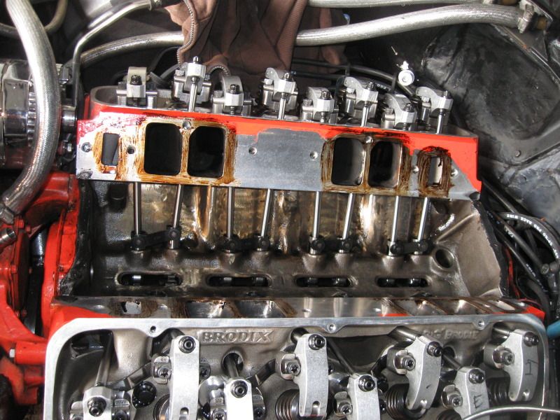
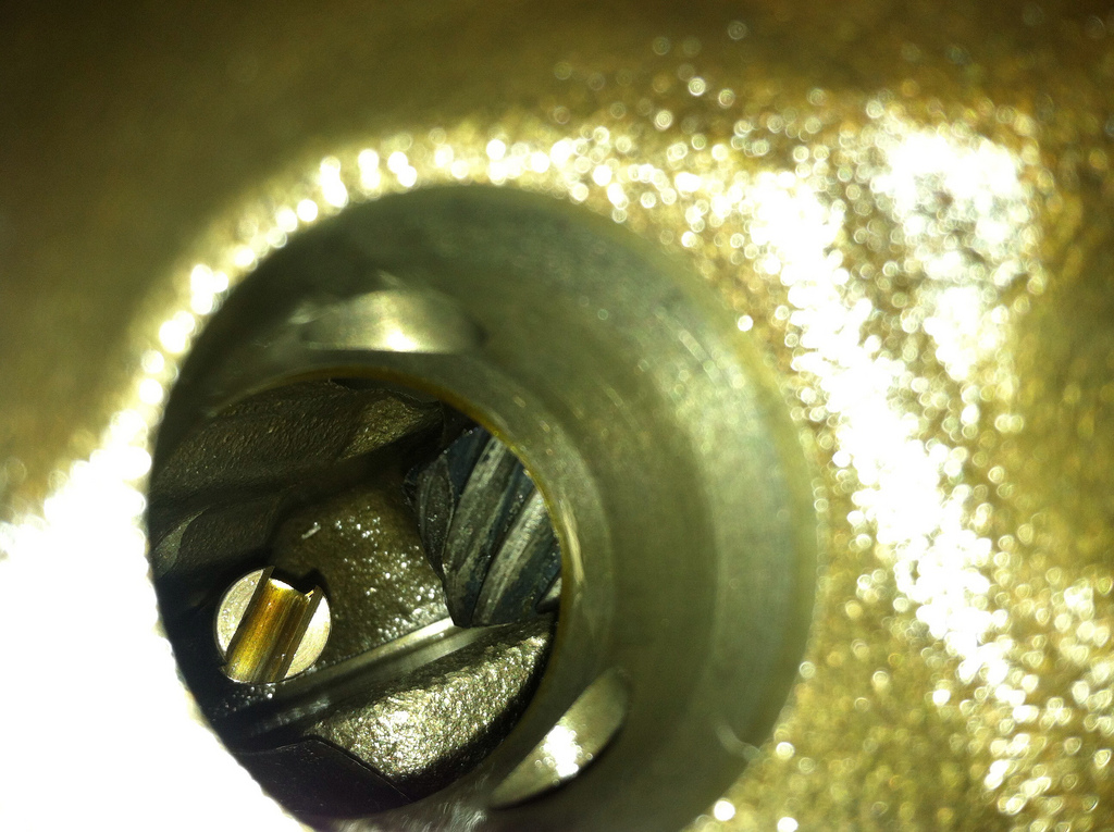
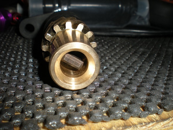
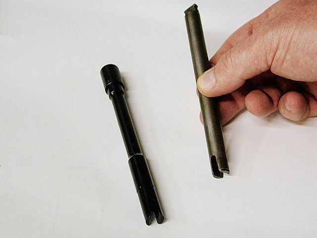
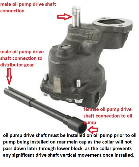
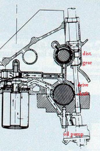
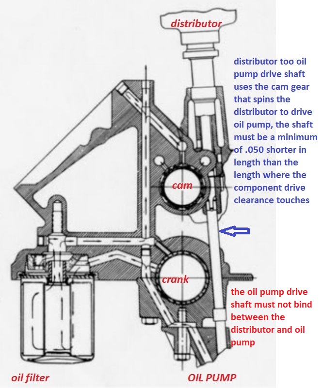
In removing the leaking intake, special care should be taken to insure no foreign particles fall into the lifter valley or down the holes in the block used for oil drain-back or the distributor/oil pump drive. It may be difficult to prevent every piece from falling in, but if one does, be sure to pick it/them out.


Next, all the mating surfaces must be cleaned thoroughly to be free of any oil, coolant or gasket material. YO!, and I mean THOROUGHLY! Both the block AND the underside of the intake manifold.

This can be done using something as simple as carburetor/brake cleaner. I prefer brake cleaner since it leaves virtually no residue. Go over the surfaces several times to be sure all residue has been removed. This is critical to allow the sealant to, well, seal and not move.

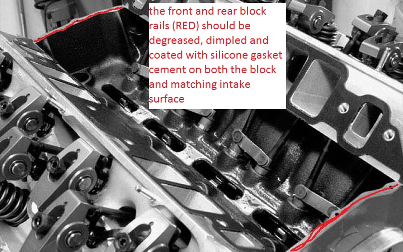
Once the block, heads and intake are squeaky clean it's time to improve the ability of the sealant to adhere. I specified sealant since the cork or rubber END gaskets that still come with some intake manifold gaskets SHOULD NOT BE USED - DISCARD THEM! We won't be using them on the China Walls.

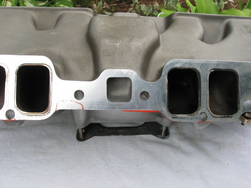
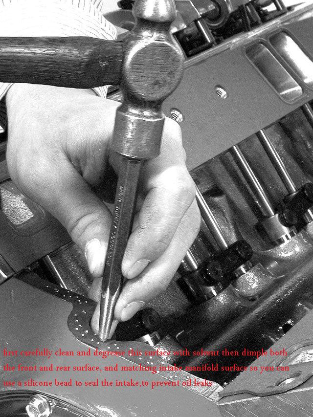
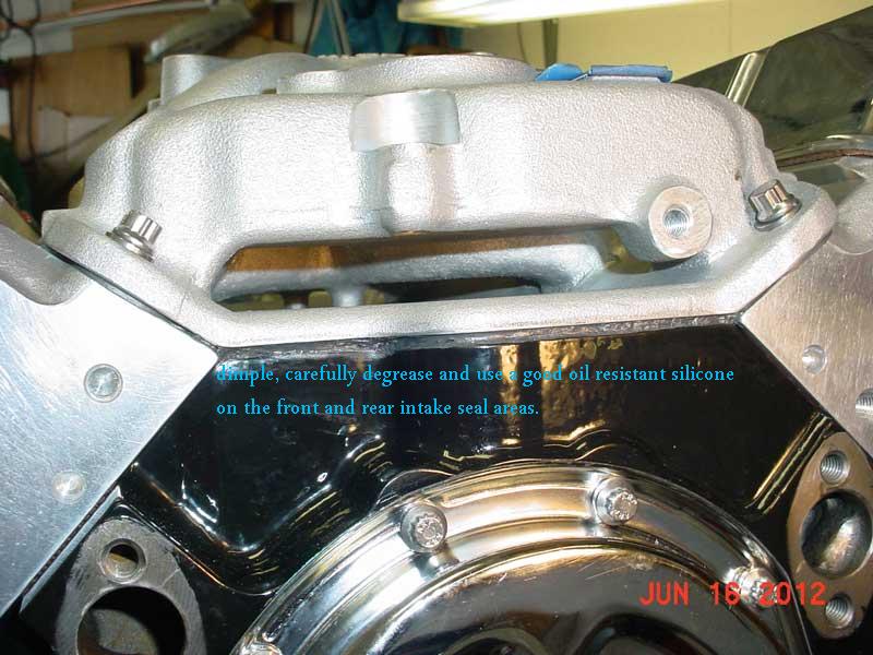
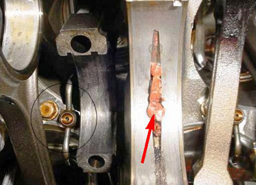
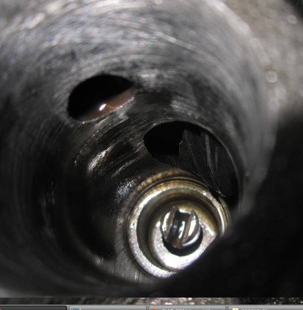
I then dimple BOTH China Walls (front and rear) on the block using a nail set; this is the Old School/Old Racer's trick. I also do the same dimpling on the corresponding areas on the underside of the intake manifold, both front and rear. Position the nail set and WHACK-O!
The little dimples give the silicone sealant (to be applied later) something to "bite" into.

Although I've never actually counted them, I guess I end up with around 30 or more dimples at each of the four locations. I space them about 1/8" apart.

I have a photo of the dimples I installed on my 388 if you're interested. I'd post it here, but I think it would 'time-out' over time and no longer be viewable.

I simply use a normal claw hammer and a nail-set to create the dimples. (A member of another Forum emailed me for the Sears part number of the nail set I use, GEEZZ, LOL)

The dimples only have to be deep enough to grab your finger-nail. The process is easy to do and doesn't take long.

After all are done, I wipe down the areas with a rag wetted with brake cleaner a few times. The cleaner will evaporate quickly leaving a clean, dry surface.

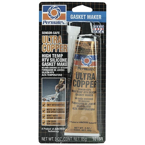
I use Permatex Sensor-Safe Silicone Sealant (SSSS), this is the New School trick. I apply a thin layer on BOTH sides of the intake gaskets and apply it around all the intake ports and all the coolant openings (if the intake manifold has them). I apply it with my wetted fingers in a manner so that it's relatively smooth. Wetted fingers keeps it from sticking to me.

Keep it 1/4" or so away from the openings so that there's no chance of it getting pressed into the port when the intake is bolted on. Remember, you're only applying a thin layer; nothing like the China Walls are about to get, LOL. What we're after is NO vacuum or coolant leak, period!

Some prefer using other sealants, like 'The Right Stuff', etc., but Permatex SSS has always worked for me - so "If it ain't broke don't fix it." is my train of thought. Also, be aware that others have reported on how hard "The Right Stuff" is to remove should the need arise. Your choice though.

Then I set the intake manifold gaskets in place and lightly press down on them to position them correctly on the cylinder heads.

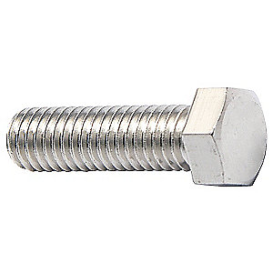
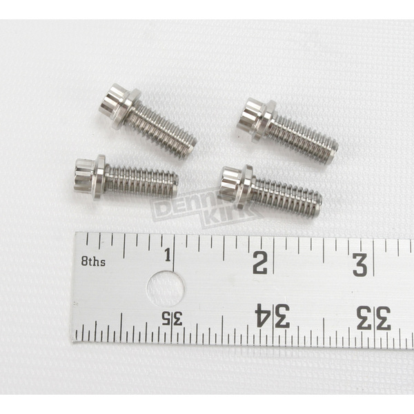
I then apply a 3/8" diameter bead of SSSS to the China Walls. I use a 3/8" bead rather than the 1/4" bead you may see in some manuals. I've found that a 3/8" bead seals better. If you're unsure of the diameter, just take a look at the diameter of the threaded end of a intake manifold bolt; that's 3/8".

I carry those beads, unbroken, up and onto the four corners of the intake manifold gaskets to seal the areas where the intake meets the cylinder heads and block. Don't forget to do this.

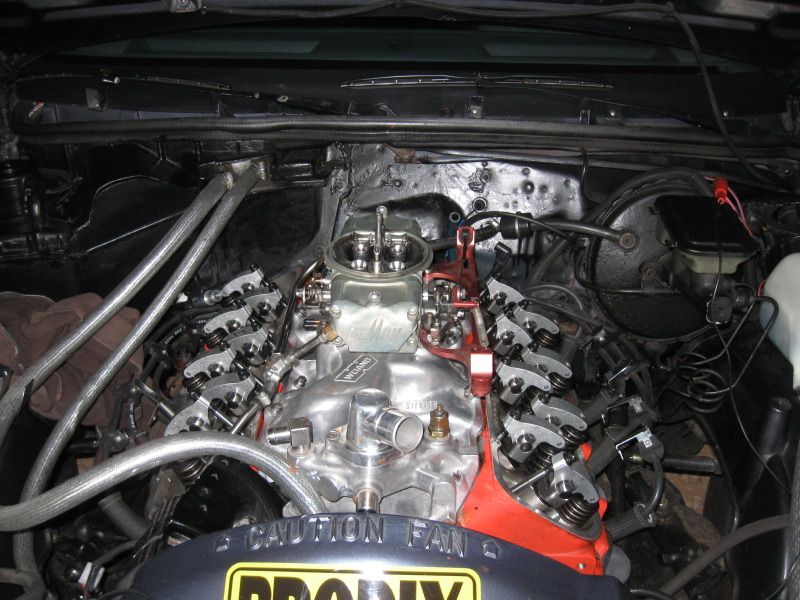
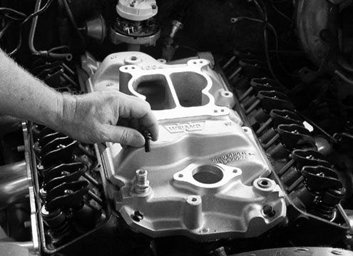
I then immediately install the intake manifold, BEFORE the SSSS skins over. I want the SSS, while still wet, to be able to flow into any crevice and especially the dimples. Once it cures, usually 24 hours, the SSS is anchored in place.

When installing the intake manifold, I set the intake straight down with no back or forth movement. I look through the intake manifold bolt holes to align them with the holes in the heads.

Minimizing, or better yet eliminating any back and forth or side to side movement of the intake is best to prevent disturbing the SSSS. STRAIGHT DOWN IS THE KEY!

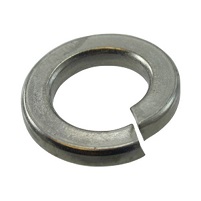
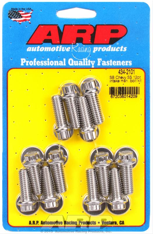
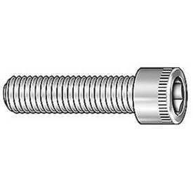
I then install all the intake manifold bolts by hand, finger tight with Anti-Seize applied to the threads. I always use washers under the heads and lube both of them with 30W engine oil. Washers installed under the heads of the intake bolts more evenly distributes the clamping force.

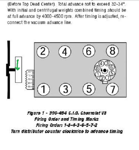
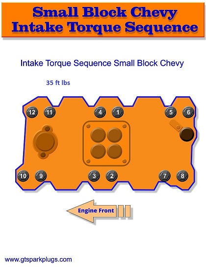
I follow the torque sequence shown in my shop manual. The torque sequence differs depending on the year/model of the engine, so you'll need to refer to a manual to see which one is recommended for the engine you're working on.

My thinking on this is 'There has to be a reason why GM recommended a certain sequence' so, absent contrary evidence, why re-invent the wheel?.

I use at least three steps to torque all the bolts to 35 ft lbs of torque. Three steps would be 15, 25, 35. If I do four steps it would be like 10, 20, 30, 35. Seems both ways work equally well and I see no need to "over engineer" this, LOL

Now here's another trick that I feel has always helped contribute to excellent sealing:

I let the intake set for an hour or so, (while I'm doing something else) then go over every bolt in the same torque sequence, tightening (re-torquing) them as needed.

It's not unusual to find that one or more bolts has lost torque due, I believe, to compression of the gaskets. I wait for another hour or so, then go over all the bolts again.

I keep doing this - going over the torque - until all the bolts hold the 35 ft/lb (lb/ft if you prefer) torque setting. After all the bolts have held the torque setting, I know I'm good to go. Even then, I go over them after the engine has gone through many heating/cooling cycles. That takes care of what heat can do to the sealing.

In torquing down the bolts, some amount of sealant on the China Walls will be forced out - Not a problem. Once cured, the SSS won't break off and those of you who may be concerned about piece of SSSS falling into the lifter valley needn't be. It won't happen.

For those who may be somewhat anal and who wish to remove the small amount of SSSS which protrudes from the exterior of the China Walls, be sure to wait until the SSSS has fully cured. Then take a very sharp razor blade and slice away the unwanted sealant. I never do, preferring NOT to chance disturbing the seal.

Should it ever become necessary to pull the intake again - like when swapping cams, etc., - the SSSS that's been compressed into the dimples can be easily removed.

If it's done like this, the sucka won't leak down the road.

Hope this helps.

Jake "
 
My brother in law has a 1974 corvette, that has been discussed before

its a 4 speed manual with what was originally a 270hp LS4 454 engine, but now with Dougs side pipe headers and an Edelbrock single plane intake
it will smoke the tires but its basically past peak power by 5000rpm due to the stock mild cam.

http://vettefacts.com/C3/1974.aspx

mitch2.jpg

well he is not great at following suggestions and he failed to degrease and dimple the block and intake front and rear rail area when installing the new intake manifold so as a result he has a annoying minor oil leak we need to fix, all that could easily have been avoided if he had simply followed the suggested method of getting a good intake seal. so it looks Like Ill be spending 30 minutes or a bit more doing a minor repair, which i really don,t mind doing other than its a parts failure totally due too and the result of, a failure to previously follow directions borne of experience in a rush to get the new intake installed.
as many of you know some companies no longer include the plastic end rail seal strips in the intake gasket sets because they tend to slowly squeeze out from between the intake manifold and block rails and many experienced mechanics have simply switched to running silicone sealant beads, in that area
yes, be sure too dimple and degrease both the matching lower intake manifold where it seals to the block rail and the upper block rail surface in the picture, before you place a 1/4 or so bead of sealant on both surfaces that will flow together and seal as the parts are mated and the bolts holding the intake spread and squeeze the silicon sealant between them


dimplea.jpg

FrontIntakeSeal_2544a.jpg

bbcintakez.jpg


copseal1.jpg

GOOD SILICONE SEALANT

acetonec.jpg

alcohol.jpg

toluene.jpg


IF you find the engines hard to start after a cam instal, theres a very good chance you installed the cam using the DOT-TO-DOT method and you forgot to rotate the engine one full revolution BEFORE dropping the distributor into the engine, you might be reading the info incorrectly, cams are generally installed using the DOT-TO-DOT method for easy installation without a degree wheel, this places the cam timing at TDC on the number 6 cylinder, simply rotating the engine one complete revolution after the cams installed using the DOT-TO-DOT method, brings the #1 cylinder up to TDC , thats when you drop the distributor into the engine with the distributor rotor facing cylinder #1
(remember the cam rotates at 1/2 the speed of the crank, so every other full rotation brings the cam and crank timing in alignment at TDC for number 1 cylinder.
If theres one constant fact I learned the hard way early on in this hobby its the fact that , most of us learn from our mistakes,and yes IVE made my share, but I do learn not to repeat the same ones twice,
30 minutes spent reading instructions very carefully can save hours of wasted effort
Use the correct sealants and minimal amounts, be well aware that excess silicone sealant that squeezes out from between surfaces , might become loose debris that can and frequently will rapidly kill any engine, as it follows oil flow, especially if its blocking oil flow and it won,t take much to do that

all that extra silicone sealant that gets squeezed out off the gaskets tends to get carried by the oil flow into the oil pan where some of its trapped in the oil filter during each successive trip thru the engine, but bits that get trapped in the oil passages can rapidly reduce oil flow and destroy bearings, cam lobes and rockers and lifters.
cloggedbearing.jpg

but once it reaches the bearings the clearances are far tighter and either they restrict oil flow or get trapped and damage the bearings, cam lobes lifters,rockers or crank journals
read threads
http://garage.grumpysperformance.co...oil-passages-and-improved-oil-flow-mods.3834/
check both the oil pump pick-up to oil pan floor clearance ,
and oil pump drive shaft length very carefully

http://garage.grumpysperformance.com/index.php?threads/installing-an-oil-pump-pick-up-tube.1800/

http://garage.grumpysperformance.com/index.php?threads/oil-pump-drive-shafts.123/#post-19025

http://garage.grumpysperformance.com/index.php?threads/oil-system-mods-that-help.2187/

http://garage.grumpysperformance.com/index.php?threads/distributors-wont-seat-on-intake.12538/

http://garage.grumpysperformance.com/index.php?threads/distrib-gear-issues.11291/#post-51208

http://garage.grumpysperformance.co...-convinced-its-the-oil-pump.11085/#post-49370

http://garage.grumpysperformance.com/index.php?threads/oil-pump-shaft.4966/#post-13781

http://garage.grumpysperformance.com/index.php?threads/installing-distributor.9946/#post-38325

http://garage.grumpysperformance.com/index.php?threads/distributor-gear-wear.1701/#post-4658

http://garage.grumpysperformance.com/index.php?threads/shiming-a-distributor.251/#post-1366

http://garage.grumpysperformance.co...p-that-just-won-t-clamp-firmly.871/#post-1359

http://garage.grumpysperformance.co...-high-press-or-both-oil-pump.2294/#post-11706
scan0001.gif

ID suggest verifying TDC and the use of timing tape on the damper and a decent timing light rather than guessing.

once youve located TRUE TDC, you either install timing tape on your current damper, or a marked cover
timingtape1.jpg

then graphing your advance curve

http://garage.grumpysperformance.com/index.php?threads/timing-lights.875/

http://garage.grumpysperformance.com/index.php?threads/timing-tabs-and-indicators.1015/

http://garage.grumpysperformance.com/index.php?threads/verifying-your-real-advance-curve.4683/

chart3e1.jpg

this is usually a good start point

timingsdia.jpg


http://garage.grumpysperformance.com/index.php?threads/timing-tabs-and-indicators.1015/

http://garage.grumpysperformance.co...our-real-advance-curve.4683/page-2#post-35828

http://garage.grumpysperformance.co...lem-getting-the-engine-started.63/#post-31920
GOOD DEGREASERS , USE ANY TWO
re-read this threads earlier posted info
viewtopic.php?f=55&t=464

RELATED POSTED THREADS
viewtopic.php?f=54&t=206&p=390&hilit=sealant#p390

viewtopic.php?f=50&t=50&p=1253&hilit=sealant#p1253

viewtopic.php?f=44&t=700&p=1095&hilit=sealant#p1095

viewtopic.php?f=44&t=849&p=1306&hilit=copper+coat#p1306
 
Last edited by a moderator:
BTW, I occasionally find I'm working with some guys who either lack experience or are clueless as to their options, when bolting an intake manifold down on an engine.
Ive watched guys fight for 20 minutes trying to tighten the standard 9/16" hex head machine bolts on some intakes where access was very limited

Coarse-Thread Socket-Head Bolts - 3/8in.-16 (thread) x 1 1/4inch (length).

most guys are familiar with use of standard HEX HEAD BOLTS
36RG04_AS02.jpg

when used on a chevy aluminum intake manifold you'll frequently find, the required room,for easy access with a box or open end wrench is very limited due to the intake runner proximity to the threaded holes center line,
and that after some time standard bolt heads tend to rust and dis-color aluminum intakes.

now ideally youll use a lock washer, under the bolt head and ANTI SEIZE on the bolt threads
lockwas.jpg

that prevents vibration and heat cycles from allowing the bolts to back out of the threaded holes.
there are both 6 and 12 point, reduced bolt head size , stainless bolt sets available that allow increased clearance

intablt1.jpg

intablt2.jpg


capscrew1n.jpg


STAINLESS STEEL socket head cap screws make a much neater look ,
are less likely to rust,and allow far more clearance around the bolt heads, both standard and TORX versions and several head designs are available
BUTTON HEAD VERSIONS MAKE FOR A CLEAN APPEARANCE


1CET2_AS01.jpg

spec2.jpg


sbcIntaketqx.jpg

spec3.gif

spec1.gif
 
Last edited:
Good info Grumpy.
I have been using Permatex Ultra Grey Silicone on V8 engine China walls for some time now. Around 8-9 years.
Not a real big fan of Right stuff black silicone but many like it.

I may Try Ultra Copper RTV on the Suburban 350 TBI China walls.
Once in a while I have seen Grey Silicone RTV fail...others did the work...maybe bad surface prep.
I think also modern synthetic oils perhaps attacked long term.
 
grumpy, no mater how hard I tighten the distributor clamp on my intake manifold,
I will almost enviably, find its moved and will require re-timing. any ideas?

Ive seen this frequently, and almost always its a case where if you measure carefully, youll almost surely find,
the oil pump drive shaft is bottoming out solidly between the oil pump and the distributor gear is binding,
so the distributor is not firmly seated against the intake manifold surface.
distriboilpassage.jpg

the oil pump drive shaft length MUST BE about .050 SHORTER than the distance it would take to firmly seat it inside the distributor drive gear, the cam has a gear that spins the distributor and the oil pump drive shaft is driven by that distributor gear in the lower distributor that extends down to the oil pump drive.


lt1i.jpg


lt1dddd.JPG

this gear must not bind on the distributor too oil pump drive shaft when the distributor is seated firmly on the intake manifold and clamped into place there must be about .050 clearance minimum
148_0506_how_09_z.jpg

sbcoilpj.jpg


ctrp_0606_gear_01_z+distributor_installation+camshaft.jpg

opds.jpg

sbcoilh5b.jpg


related threads you should really read

http://garage.grumpysperformance.com/index.php?threads/oil-pump-drive-shafts.123/

http://garage.grumpysperformance.co...ibutors-wont-seat-on-intake.12538/#post-63636

http://garage.grumpysperformance.com/index.php?threads/oil-pump-drive-shafts.123/#post-19025

http://garage.grumpysperformance.co...ing-an-oil-pump-pick-up-tube.1800/#post-43110

http://garage.grumpysperformance.com/index.php?threads/distributor-gear-wear.1701/#post-4160

http://garage.grumpysperformance.co...butor-clamp-that-just-won-t-clamp-firmly.871/

http://garage.grumpysperformance.co...-allows-the-distrib-to-turn-even-tighten.873/

http://garage.grumpysperformance.com/index.php?threads/setting-timing-question.1411/#post-3131
 
Last edited:
Back
Top