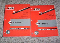
buy a CHEVY SHOP MANUAL FOR YOUR YEAR CORVETTE!
set and verify your ignition timing, pull trouble codes,set your tps and iac,, then check for vacuum leaks on the lines and intake,then get out your multi meter and verify all the sensors, chances are good its a defective heat sensor or defective o2 sensor, a logical step by step approach will lead you to the problem, you'll be amazed at what you'll learn reading links. use of a shop manual and multi meter can be very helpful.
yeah its amazing how often I get guys, in the shop with big plans,
who want to buy and install a new cam,or better heads etc.
and, you ask questions and you find they are clueless,
on how to correctly tune the current engine they have,
or there is obvious several badly mis-matched parts, that have been installed.
or currently badly adjusted or defective parts, and like you will frequently find,,
as a result, there is frequently a great deal of potential power found ,
in properly tuning most cars that the current owners leave on the table ,
simply because they don,t understand the current combos potential,
and think the only possible route to better power is installing new parts.pressure is a measure of resistance to flow , without a restiction theres no pressure.
http://garage.grumpysperformance.co...ard-starting-tpi-crossfire-or-lt1-vette.1401/
http://garage.grumpysperformance.com/index.php?threads/replacing-a-c-4-fuel-pump.33/e
http://garage.grumpysperformance.com/index.php?threads/c4-c5-corvette-trouble-codes.2697/
https://www.summitracing.com/parts/anm-cp7838
and rev the engine a few times and watch the fuel pressure it should in theory remain in the 38 psi-42 psi range for most TPI and TUNED PORT efi
 www.harborfreight.com
 www.harborfreight.com
http://www.harborfreight.com/5-in-1-dig ... 98674.html
www.harborfreight.com
http://www.harborfreight.com/5-in-1-dig ... 98674.html
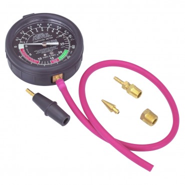
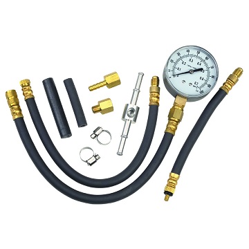
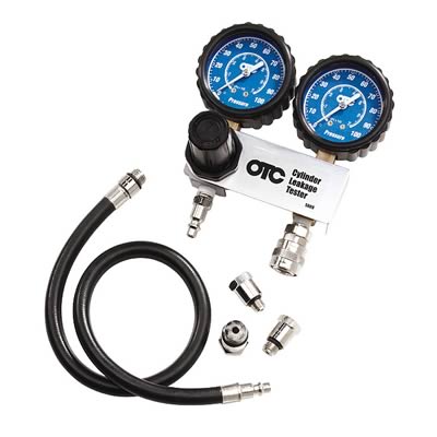
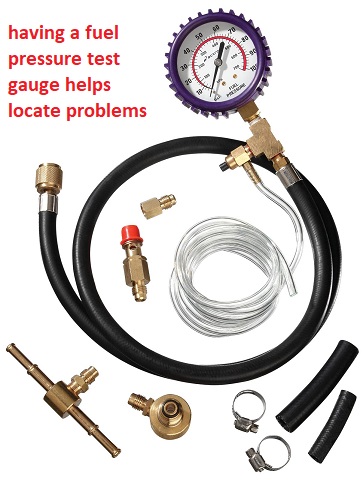
a vacuum and fuel pressure gauge is useful
learn to use the factory shop manual, and a multi meter and LISTEN to the engine closely, tapping and high pitch whines can indicate defective injectors or fuel pressure regulators, fuel pumps,mis- adjusted valve train components, worn distributor parts, check all the fuses and electrical grounds and corrosion on connections thats something thats frequently over looked etc. this process of finding the cause of a problem, is basically a detailed check list and once you understand what your looking at and what its supposed to do after each components tested, is basically a simple procedure if you test, and eliminating potential sources until you narrow it down to the cause, where you prove it then re-place, repair or adjust as required.
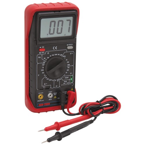
yes youll need to have some test equipment like, a shop manual, multi- meters and pressure gauges, timing lights etc. but its not that difficult.
RULE#1
never assume a damn thing ISOLATE ,TEST AND VERIFY
ANY TIME YOU SUSPECT FUEL INJECTOR OR FUEL SYSTEM RELATED ISSUES ,A REASONABLE START POINT IS TO USE A GOOD QUALITY FUEL INJECTION CLEANER ADDITIVE IN THE FUEL TANK AND SWAP TO A NEW FUEL FILTER
http://www.bgprod.com/catalog/gasoline- ... m-cleaner/
http://www.bgprod.com/catalog/gasoline- ... m-cleaner/
http://www.chevythunder.com/Flow chart index.htm
http://www.professionalequipment.com/ex ... ermometer/
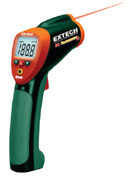
having a good cross check tool like a quality IR temp gun, and a decent multi meter, sure helps find the truth as far as a defective gauge or sensor
http://chevythunder.com/
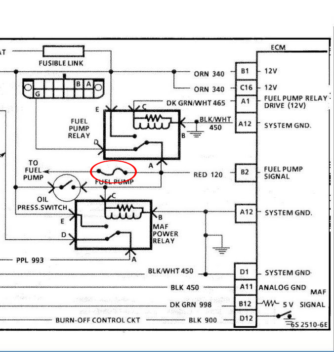
L98/ TPI Engine Start Sequence
When you start an L-98 engine Corvette, a series of events take place that causes the engine to run. Knowing the sequence will help you troubleshoot no start conditions.
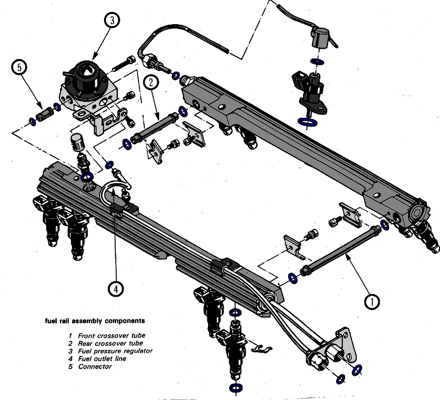
Fuel Rail Pressurization:
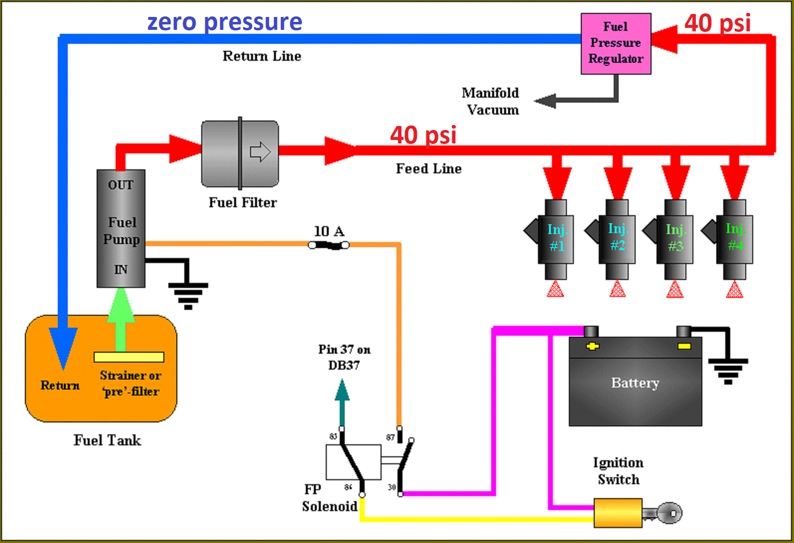
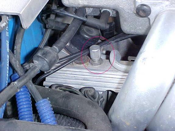
When you first turn the key to the “on” position, the fuel pump will run for 2 seconds pressurizing the fuel rails. There is a Shraeder valve on the passenger side fuel rail near the rear of the engine and if you measure the pressure there after the pump runs, you should see between 40-42 pounds of pressure. The reading will go to 38-40 pounds nominal once the engine is running.
Initial Crank Action:
If you then rotate the key to the start position (assuming the anti-theft system has not disabled the starter), the engine will rotate.
Once the oil pressure has reached 4 PSI, the oil pressure switch will close allowing the fuel pump to run. (Note that you should have a black oil pressure switch/sender. It is mounted behind the distributor on the driver’s side and if it is not black, it is suspect due to a run of bad units that stayed in the GM parts pipeline for some time).
The distributor will send a string of pulses to the ECM (Engine Control Module) in response to the engine being rotated by the starter. These pulses continue as long as the engine turns (both starting and running) and if they are not present, the engine will not run.
ECM Reaction:
If the ECM sees oil pressure greater than 4 PSI and the reference pulses from the distributor, it will energize the injector drivers which will begin pulsing the injectors on for 4 ms (milliseconds) periods. (In the L98, all injectors on one side of the engine fire at the same time followed by all injectors on the other side firing at the same time. On the LT-1, the injectors are fired individually at the appropriate time).
The ECM will also pull in the fuel pump relay in effect paralleling it electrically with the oil pressure switch. (If the fuel pump relay fails, you can still normally get the car to start and run unless you can’t make at least 4 PSI oil pressure. This is a “limp home mode” feature put in place to allow for a fuel pump relay failure).
The ECM also monitors the TPS (Throttle Position Sensor mounted on the throttle body assembly) and wants to see .54 volts at this time. If it sees appreciably more than 0.54 volts, it will assume the engine is flooded and the driver has pressed the accelerator to the floor to clear the flooded condition and restrict the fuel flow as a result. (.54 volts during start and at idle from the TPS is very important to both starting and run performance.)
Assuming the ignition module is good (meaning there is a spark of sufficient intensity to ignite the fuel), the engine will “catch”.
Engine "Catches":
When the engine catches, the MAF (Mass Air Flow sensor mounted just ahead of the throttle body) sends a signal to the ECM advising that air is flowing and also just how much air is being pulled through to the intake manifold. The ECM takes note of the amount of air being consumed and adjusts the injector pulse width to around 2.2 ms nominally so as to attain a proper air/fuel mixture to insure combustion. (This is how the 1985 through 1989 L-98 works. For information on the 1990 and 1991 L-98 variant, see the Note below).
The engine should show an initial idle speed of around 900-1100 RPM and then slowly diminish to 600-700 RPM unless the air conditioner is on in which case it will run at around 800 RPM.
If this does not happen, the Idle Air Mixture valve (located on the throttle body) may be misadjusted. Alternatively, there may be a leak in the intake manifold or another vacuum leak may be present. Listen for hissing sounds---there should be none.
ECM Mode:
The engine will now be in Open Loop mode meaning that the ECM is controlling the air/fuel mixture by referencing values stored in memory.
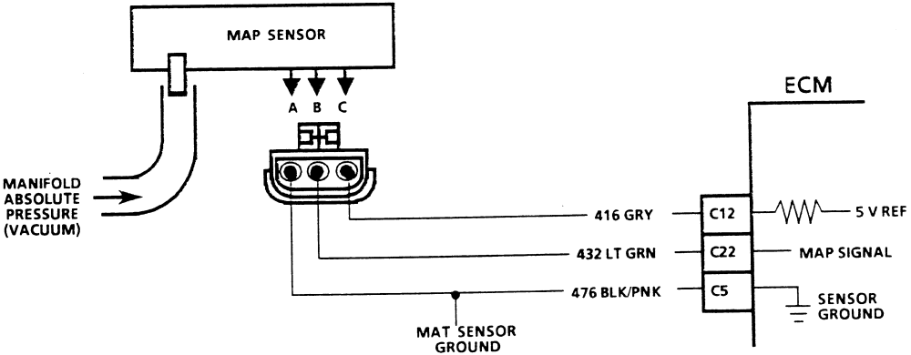
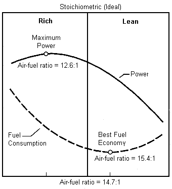
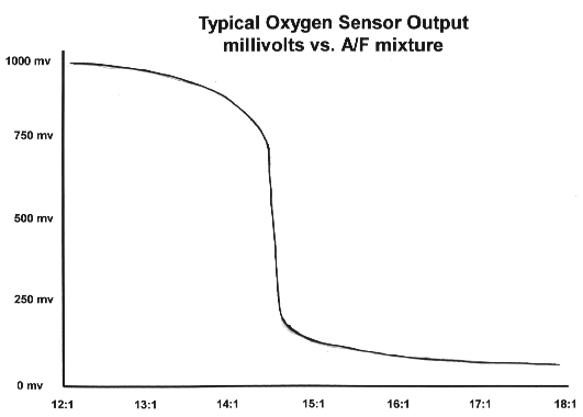
Once the Oxygen sensor (mounted on the exhaust pipe) reaches operating temperature of several hundred degrees, the Manifold Air Temperature (MAT) sensor shows an intake air temperature of more than 140 degrees and the Engine Coolant Temperature (ECT) has reached 160 degrees, the computer will switch to closed loop mode meaning the Oxygen sensor’s output is examined along with the MAT and ECT outputs and the ECM adjusts the injector pulse widths (more “on time” or less “on time”) to constantly strive for a 14.7:1 air/fuel mixture which is the best mixture to hold down pollution.
Note that prolonged idling can force the computer back into open loop mode.
Note: In 1990, the MAF was eliminated from the engine in favor of a speed/density system. This system uses a sensor called the MAP sensor which measures the Manifold Absolute Pressure (hence the name MAP) and compares it with the atmospheric pressure outside the intake manifold. This information, coupled with the Manifold Air Temperature, Engine Coolant Temperature and Engine RPM is used by the ECM to determine the amount of air entering the cylinders. It is a different way of reaching the desired 14.7:1 air-fuel mixture ratio but functionally is like the MAF system in that the ECM uses the feedback to control the "on time" for the injectors.
Corvette used this approach in the 1990 and 1991 L-98 engines and in the 1992 and 1993 LT-1 engines. With the 1994 model C4, they went back to the MAF system. Note that MAF based systems are far more accurate since they measure air flow directly whereas the MAP system infers air flow indirectly. A multitude of things can throw the calculation off and Corvette returned to the MAF system beginning with the 1994 C4 (with a MAP backup). From a troubleshooting standpoint, the MAP operation comes into the sequence the same place that the MAF does.
Summary:
If you have a no start condition or if the L-98 starts and then dies, check the above items in sequence to see if all the events are occurring as required.
A Scan Tool makes this job much easier and is a highly recommended troubleshooting aid for these sorts of problems.
youll find a hour or so reading thru the links and sub links, on this site in the threads, will provide a great wealth of related info and incite into related factors, or the function or testing of sensors, that you may not currently be thinking about, or things that you might not think that are related to your issue that PROBABLY ARE
without testing your simply guessing
EFI works at higher pressures (a 1985-1991 TPI corvette as an example generally operates in the 38psi-42 psi fuel pressure range)
THINK,
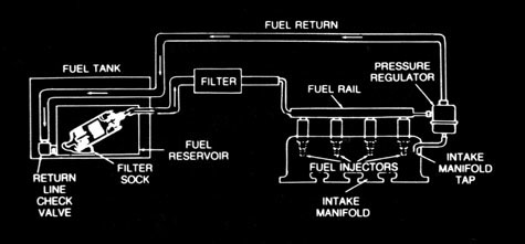
fuel tank...to .fuel filter....to .-fuel pump....to feed into fuel rail& injectors. then out too....fuel pressure regulator...then too..return line to fuel tank
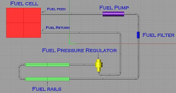
it might help if you think, fuel pump provides fuel flow volume,
fuel pressure is a measure of resistance to fuel flow,
the fuel pressure regulator acts as a valve that opens if the pressure exceeds about 42 psi (YES some versions like yours are manually adjustable) but the reason its there is to maintain a consistent 39 psi-42 psi to do that you allow the fuel pump to stack or pressurize fuel in the fuel rail and in theory the fuel pressure regulator only allows excess fuel volume to flow back to the fuel tank through the return line if that fuel pressure exceeds the 42 psi, the pump is designed to provide a bit more than the required 42 psi too insure fresh cool fuel is cooling the fuel pump while maintaining that consistent fuel volume at the fuel pressure, when you tromp on the throttle the flow of fuel drastically increases, the regulator momentarily restricts out going fuel to maintain the fuel rail pressure and volume, until the flow demand drops enough, for excess volume and the resulting increased pressure that results to open the regulator again,
WATCH VIDEO
https://www.youtube.com/watch?x-yt-ts=1 ... l=85114404
get out your shop manual and multi meter
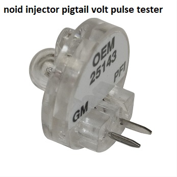
if you suspect the injectors , you first use a multi meter to verify every injector reads the same ohms (usually near 11-16 okms, and yes they should all read very closely) then you need a noid kit for a G.M. fuel injection system, these are basically little lights that light as the injector pulse hits them that you plug into the injector harness,after you remove the harness from the injectors, they plug into the harness just like an injector, if you try to start the engine and they blink on and off the pulse is reaching the injectors thus proving that the injectors get the pulse
http://www.harborfreight.com/11-piece-n ... 97959.html
if you suspect the injectors have gone bad or are locked up and your test with a NOID LIGHT TEST KIT shows the injectors are getting the required pulse from the wiring and the injectors have the required ohms resistance and you have the fuel rail pressure, but your not getting fuel, and you are getting ignition spark,its always a case of isolate and test, that finds the cause, and you start with the basics of trouble codes , and fuel, compression, spark, and timing.
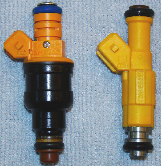
old school testing still works and if you swap the current injectors out for different injectors and nothing changes you have a good indication its not the injectors causing the problem, now the problem with that course of action is that new injectors tend to cost $300-$600 a set for 8 , thus a bit of creativity is used,
If it was my car Id have done a bit of research and located a list of cars that had compatible injectors that could be swapped in, then visit a salvage yard with a easily portable tool kit and a multi meter and found at least 16 injectors , that I could pull that passed the ohm meter test for use in testing the car, by simply swapping out the injectors wholesale after very carefully cleaning the salvage yard supplied injectors.(obviously the price will vary so ask before you go thru the effort but Ive generally paid $60-$80 for a set of 8 used injectors which I test with an ohms meter before I remove them, and having a spare set is certainly worth that)
heres a link to swapping injectors
http://www.thirdgen.org/injectorswap
read thru these links
AND YES AMAZINGLY, ACTUALLY READING THRU THE POSTED LINKS AND SUB LINKS might help
http://members.shaw.ca/agent86/Fuel Control And Delivery-8A.pdf
http://members.shaw.ca/corvette86/EngineCranksButWontRun.pdf
http://members.shaw.ca/corvette86/FuelSystemDiagnosis.pdf
http://members.shaw.ca/corvette86/No-Service Engine Soon - Light.pdf
http://members.shaw.ca/corvette86/SES Light On Steady.pdf
http://members.shaw.ca/corvette86/Non Scan Diagnostic Circuit Check.pdf
http://members.shaw.ca/corvette86/Engine to ECM Wiring Diagram 86.pdf
http://members.shaw.ca/corvette86/Component Location View 86.pdf
viewtopic.php?f=80&t=1470&p=3304#p3304
http://members.shaw.ca/corvette86/FuelSystemDiagnosis.pdf
http://www.youtube.com/watch?v=49WXmzfO ... e=youtu.be
http://forum.grumpysperformance.com/viewtopic.php?f=32&t=596
http://forum.grumpysperformance.com/viewtopic.php?f=32&t=2697
http://garage.grumpysperformance.co...questions-can-be-found-here.12892/#post-66934
http://forum.grumpysperformance.com/viewtopic.php?f=32&t=1401
if its blowing fuzes , or some components not working that did previously,somethings changed, theres frequently a bad ground , loose connection, corrosion,or a short some place,in the wiring or a defective sensor, that needs to be located,and isolated then corrected, pull the trouble codes and use the meter to check amps, ohms and voltage and verify all sensors, the shop manual has wiring diagrams
http://forum.grumpysperformance.com/viewtopic.php?f=80&t=728&p=9217&hilit=sensor+ohms#p9217
http://forum.grumpysperformance.com/viewtopic.php?f=52&t=4410&p=11602&hilit=propane+leaks#p11602
http://forum.grumpysperformance.com/viewtopic.php?f=44&t=882&p=1390&hilit=propane+leaks#p1390
http://forum.grumpysperformance.com/viewtopic.php?f=32&t=168
http://forum.grumpysperformance.com/viewtopic.php?f=32&t=1401
http://www.corvettephotographs.com/c4vettes/codes.htm
http://www.corvettephotographs.com/c4ve ... launch.htm
WHEN TESTING<be sure the fuel pressure gauge reads correctly by comparing it to a second test gauge, these fuel pressure gauges are frequently defective
http://www.harborfreight.com/fuel-injec ... 92699.html
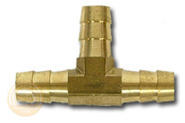
this cheap fuel pressure test gauge works ok, you just need to figure out how to tap into the fuel rail or line and that varies between years but certainly not a difficult issue to either remove a shrader valve and insert an adapter barb fitting or splice a TEE into a fuel line as a temp. test point, certainly any mechanic has an assortment of the common barb fittings required in a test kit
THE CHEVY shop manual will probably cost less than the trip to the dealership if you don,t and its useful life will far exceed that trip also!
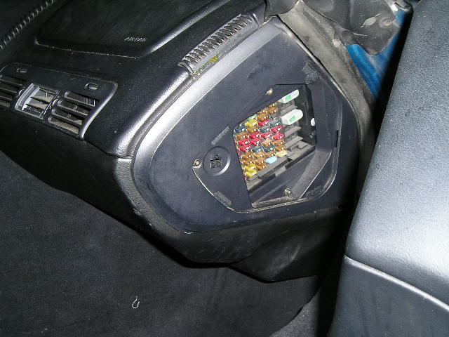
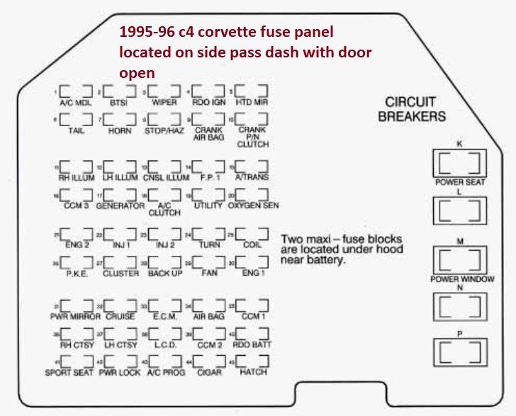
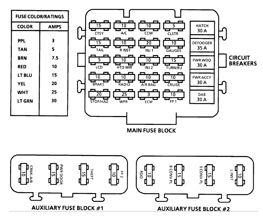
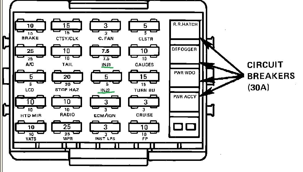
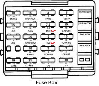
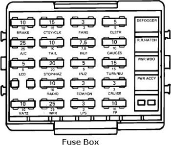
first check your shop manual for the fuse and fuse able link locations
fuses are located in several locations and fuse-able links near the battery
STEP ONE IS ALWAYS GET A FACTORY SHOP MANUAL, AND READ THE LINKS BELOW
Verify fuel pressure,. by using a fuel pressure gauge on the shrader valve on the fuel rail, with a pressure gauge,
Verify injector pulse by using a noid light, & spark at the plugs by using a spark tester.
verify timing with a timing light
pull the trouble codes and check all fuses
CHECK ALL YOUR FUSES WITH A MULTI METER
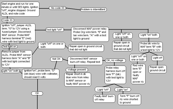
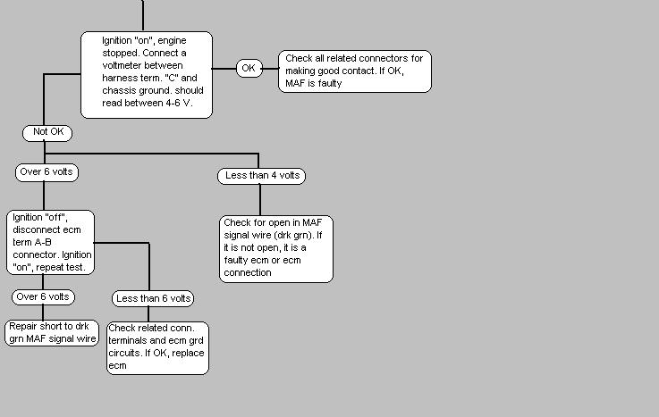
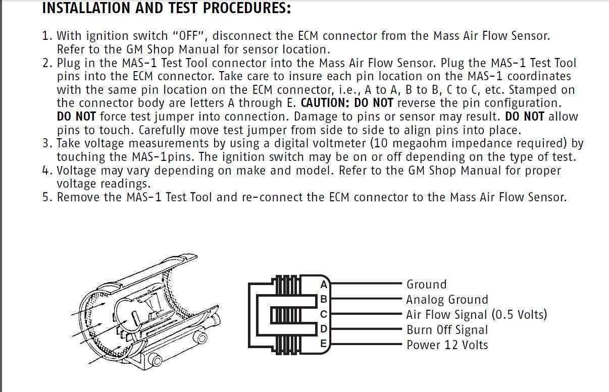
MAF Problems
Faulty MAF sensors will normally light the check engine light on the drivers information center if the problem is constant and store a trouble code. If intermittent, a trouble code will still be stored as long as the battery is not disconnected.
Normally, the problem is a poor connection at the sensor and wiggling the wires, unplugging and reinserting the connector will often cure the problem.
A faulty MAF will normally cause a no start or difficult start condition and although you can eventually get the car into the "limp-home" mode in most cases, you need to attend to the problem ASAP.
AC/Delco sensors can become intermittent or give false readings if the wires become contaminated as explained above.
The MAF is a critical part of the emission control system and as such will cause the computer to react to problems very quickly, setting trouble codes and reducing performance in ways that cannot be ignored for long.
MAF Mods
The Bosch MAF is often modified by removing the two screens that are present in the front and rear of the cylinder. Removing these screens significantly increases the air flow through them and this results in more horsepower. Removing the screens is an old trick from the Corvette Challenge days in 1988 and 1989. It does work but is illegal in many states so be advised not to do anything that will get you arrested for a pollution violation.
The AC/Delco MAF is not readily modified. It is what it is but since it is a larger diameter than the Bosch, it responds well to changing the air filter to a free flowing type such as the K&N filter."
http://www.mamotorworks.com/corvette-c4 ... 6-893.html
http://content.mamotorworks.com/pdf/601096.pdf
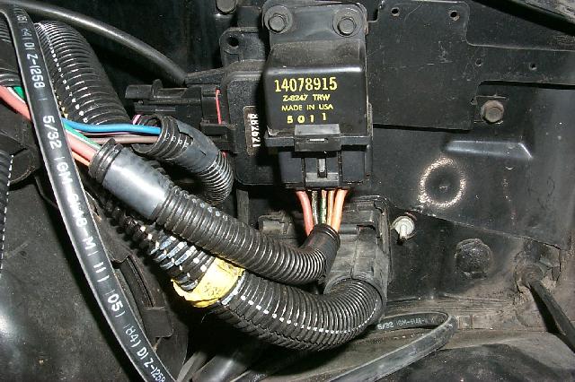
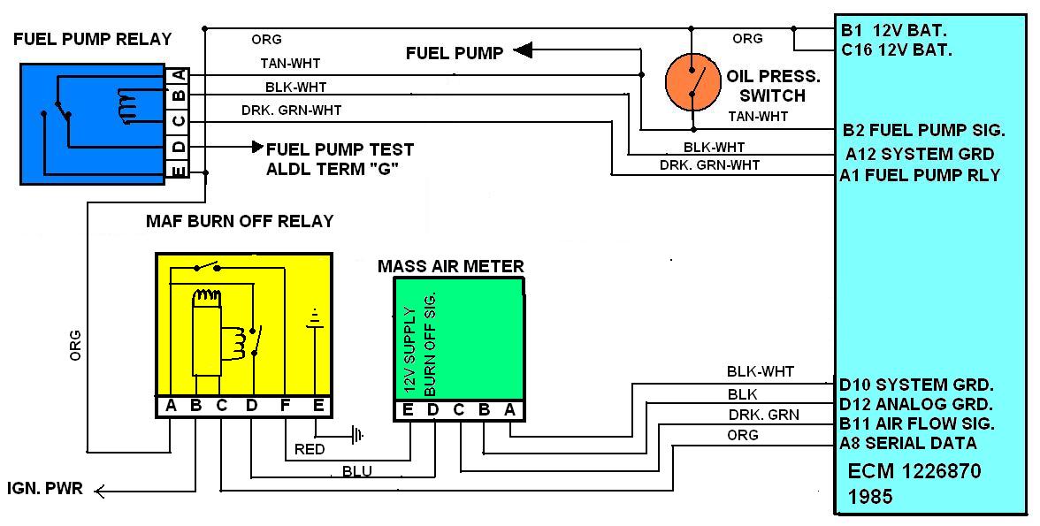
1985 fuel pump relay
probably 80% of the small screw-ups like your experiencing (and your not alone everyone has those screw-ups , adjustments and programing glitches or problems with their car) that can be corrected with a few minutes reading and carefully following directions with a shop manual.
a few tests and getting the facts before you start throwing parts at a problem,beats guessing every darn time, keep in mind,wet, loose, or broken electrical connectors or corrosion on connectors, is also possibly a cause of intermittent problems
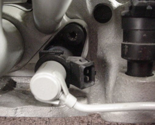
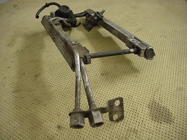
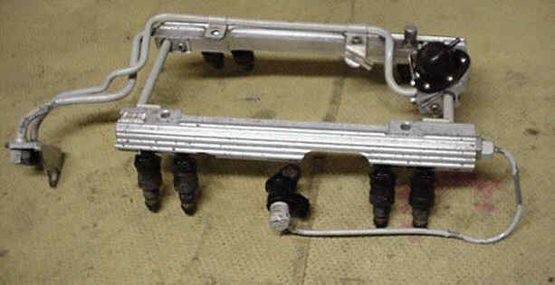
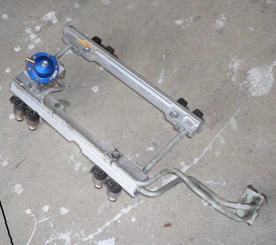
If youve got an early year TPI , thats designed to use a 9th cold start injector,check the cold start injector as its a potential problem source if its not working correctly.The cold start injector is between the front and rear pairs of runner tubes on the driver-side.on early TPI engines if its not working or loose causing a vacuum leak starting the engines much harder, later versions did not use these
if you have at lease 38 psi in the fuel rail, and it holds at or near at least 38 psi for at least a couple minutes after you stop cranking the engine, the fuel pressure regulator is most likely functioning correctly, but you state the injectors are not squirting fuel and the pump keeps running while you crank the engine?
you can test the electrical connectors on the injectors with a noid test light to watch the electric pulse,at each injector location, ID verify timing injector resistance,and check for vacuum leaks while testing, and remember theres a 9th cold start injector on the 1985-88 TPI fuel rail
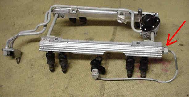
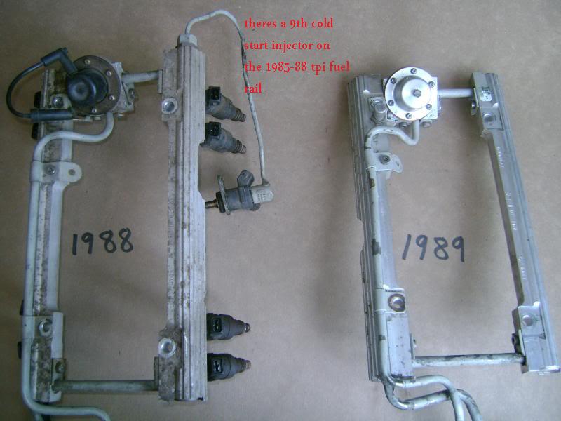
the CORRECT ANSWER to what the cold start injector looks like that I get asked rather frequently, depends on what year, TPI you have, this is the early version like on the 1985 and it takes a unique injector, and its no longer available from chevy. they are also well know sources for vacume leaks
Almost every one of those OEM fuel rail & fuel line set ups ON A TPI OR LT! has by this time had some damage and almost all of them work and function reasonably well in spite of what is more than likely mostly cosmetic rather that true mechanical damage in that its un-likely to significantly restrict fuel flow
verify the fuel pressure with a fuel gauge connected to the shrader valve on your TPI fuel rails,

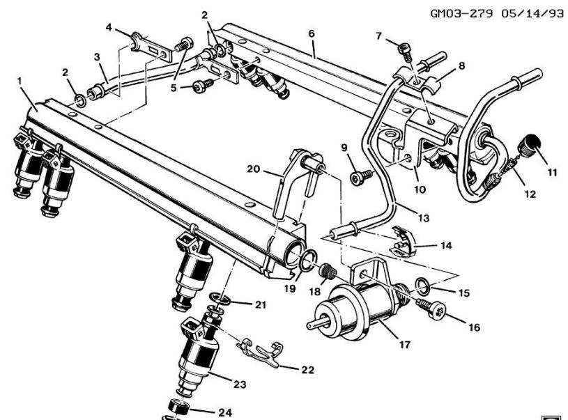
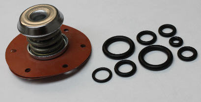
GM part number for the complete fuel rail o-ring kit is 17111696
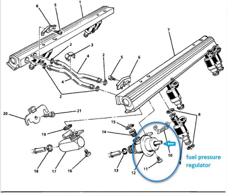
if your TPI FUEL PRESSURE REGULATOR DIAPHRAGM LEAKS youll find it difficult or impossible to be starting your car
heres a link to the correct o-rings they are light blue
NAPA sells them at times
all the o-rings on the fuel rails and injectors need to be dipped in thin oil so they insert and slide into place with less friction, this tends to greatly reduce the chance of the o-rings ripping, and yes you need the correct o-rings that fit correctly to begin with if you expect the rings to seal correctly
http://tpiparts.net/inc/sdetail/10950/300
17113544 - Injector Seals
17111696 - O-Ring Kit
22514722 - Fuel Inlet O-Ring
22516256 - Fuel Inlet O-Ring
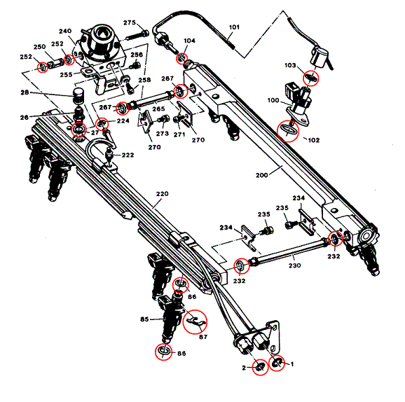
The above part numbers provided me with all of the seals shown below circled in red. I would recommend that you replace these seals whenever you service your TPI system. Remember, you've got gasoline under about 45 pounds of pressure flowing through the fuel rails etc. A leak could easily catch fire and cost you your car.
RELATED THREADS
9
STOCK TPI,LTI,LSI ENGINES USE HIGH IMPEDANCE INJECTORS
these links provide a great deal of useful info, so take the effort to read thru them
http://members.shaw.ca/corvette86/FuelS ... gnosis.pdf
http://fuelinjectorconnection.com/shop/ ... ductid=202
knowing whats going on and WHY can help
http://www.corvettefever.com/techarticl ... index.html
http://members.shaw.ca/corvette86/Component Location View 86.pdf
http://members.shaw.ca/corvette86/FuelSystemDiagnosis.pdf
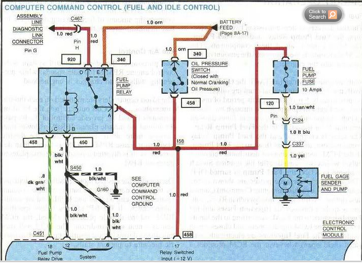
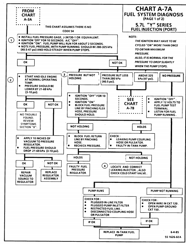
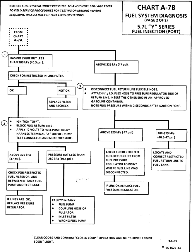
this flow chart above helps, the book below has the wiring diagrams
http://www.themotorbookstore.com/corvet ... ction.html
http://www.mamotorworks.com/corvette-c3 ... 6-891.html
http://www.mamotorworks.com/corvette-19 ... 6-900.html
http://www.autostalk.com/corvette/mass- ... ost2521803
http://www.corvettefever.com/techarticl ... index.html
http://www.rollaclub.com/faq/index.php? ... uel_System
http://www.enginebuildermag.com/Article ... stems.aspx
viewtopic.php?f=32&t=764
http://www.centuryperformance.com/fueli ... g-140.html
http://www.centuryperformance.com/fuel- ... g-141.html
YOU REALLY NEED THIS INFO
http://chevythunder.com/
KNOWING WHAT YOUR DOING IS IMPORTANT, TO GETTING GOOD RESULTS!
no one knows everything about all models and years so it helps to have the correct procedures and info in a handy reference source,now you can get by with a HAYNES or CHILTON'S manual, or something similar, but for detailed info, OWNING the CHEVY SHOP MANUAL FOR YOUR SPECIFIC CAR IS ALMOST MANDATORY!
I get asked frequently, "how did you know how to do that?"
well, EXPERIENCE plays a big roll, working on similar cars and engines helps, and the INTERNET is a good resource... but theres ALWAYS a big need for DETAILED REFERENCE MATERIAL, SPECIFICALLY MATCHING YOUR PARTICULAR CAR and if you have not yet invested in a SHOP MANUAL for the year make and model of you pride and joy muscle car your either not serious about your hobby, or most likely NOT A SERIOUS HOT RODDER! I constantly see guys SCREWING up installations, or adjustments,if you don,t know exactly what your doing, you need to either let the dealer do it and PRAY his mechanics are experienced and can read, OR..if your like ME, you would rather do it yourself and KNOW its been done correctly...
if your not aware, heres where to order them....
1-800-782-4356
http://helminc.com/helm/homepage.asp?r=
your average shop manual may cost $100-$150 ONCE! but you'll easily save far more than that in reduced time and screw ups in under a years time or in many cases on one job vs having the dealer do the work!
IF YOU DON,TY HAVE A FACTORY SHOP MANUAL FOR YOUR CAR YOUR WORKING AT A DISADVANTAGE
http://www.helminc.com/helm/welcome_sel ... M2S049ETF8
this info may help
http://www.corvettebuyers.com/ecm.html
http://www.aldlcable.com/
don,t forget to pull trouble codes in your search for answers
set and verify your ignition timing, pull trouble codes,set your tps and iac,, then check for vacuum leaks on the lines and intake,then get out your multi meter and verify all the sensors, chances are good its a defective heat sensor or defective o2 sensor, a logical step by step approach will lead you to the problem, you'll be amazed at what you'll learn reading links. use of a shop manual and multi meter can be very helpful.
yeah its amazing how often I get guys, in the shop with big plans,
who want to buy and install a new cam,or better heads etc.
and, you ask questions and you find they are clueless,
on how to correctly tune the current engine they have,
or there is obvious several badly mis-matched parts, that have been installed.
or currently badly adjusted or defective parts, and like you will frequently find,,
as a result, there is frequently a great deal of potential power found ,
in properly tuning most cars that the current owners leave on the table ,
simply because they don,t understand the current combos potential,
and think the only possible route to better power is installing new parts.pressure is a measure of resistance to flow , without a restiction theres no pressure.
http://garage.grumpysperformance.co...ard-starting-tpi-crossfire-or-lt1-vette.1401/
http://garage.grumpysperformance.com/index.php?threads/replacing-a-c-4-fuel-pump.33/e
http://garage.grumpysperformance.com/index.php?threads/c4-c5-corvette-trouble-codes.2697/
https://www.summitracing.com/parts/anm-cp7838
and rev the engine a few times and watch the fuel pressure it should in theory remain in the 38 psi-42 psi range for most TPI and TUNED PORT efi
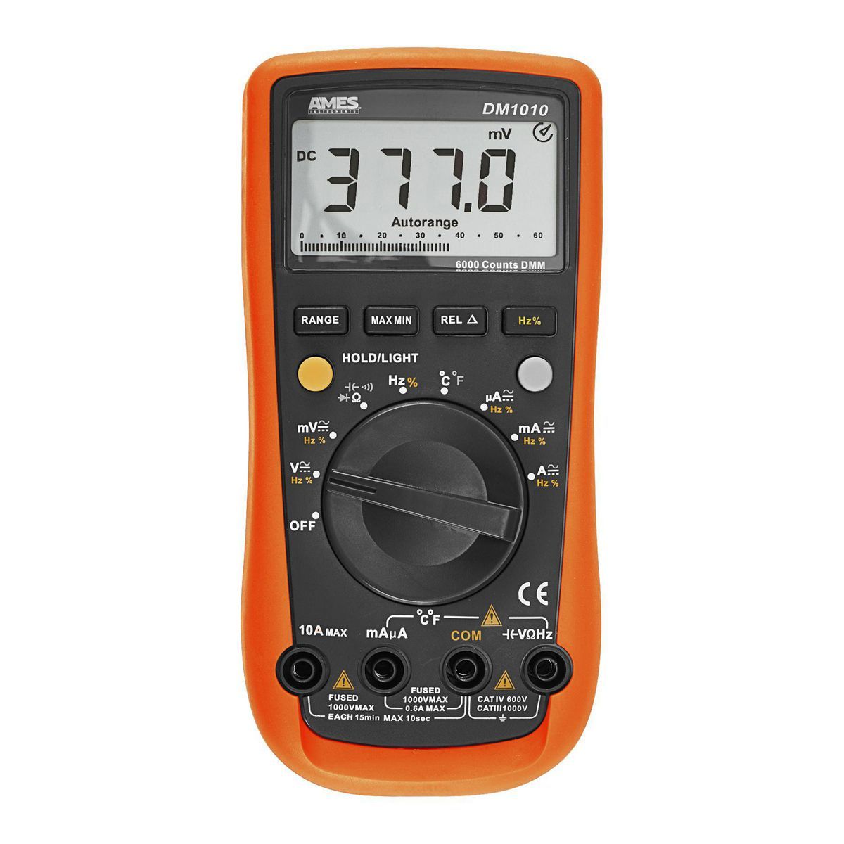
DM1010 Professional Commercial and Residential Multimeter
Amazing deals on this Dm1010 Pro Industrial Ac/Dc V Dmm at Harbor Freight. Quality tools & low prices.
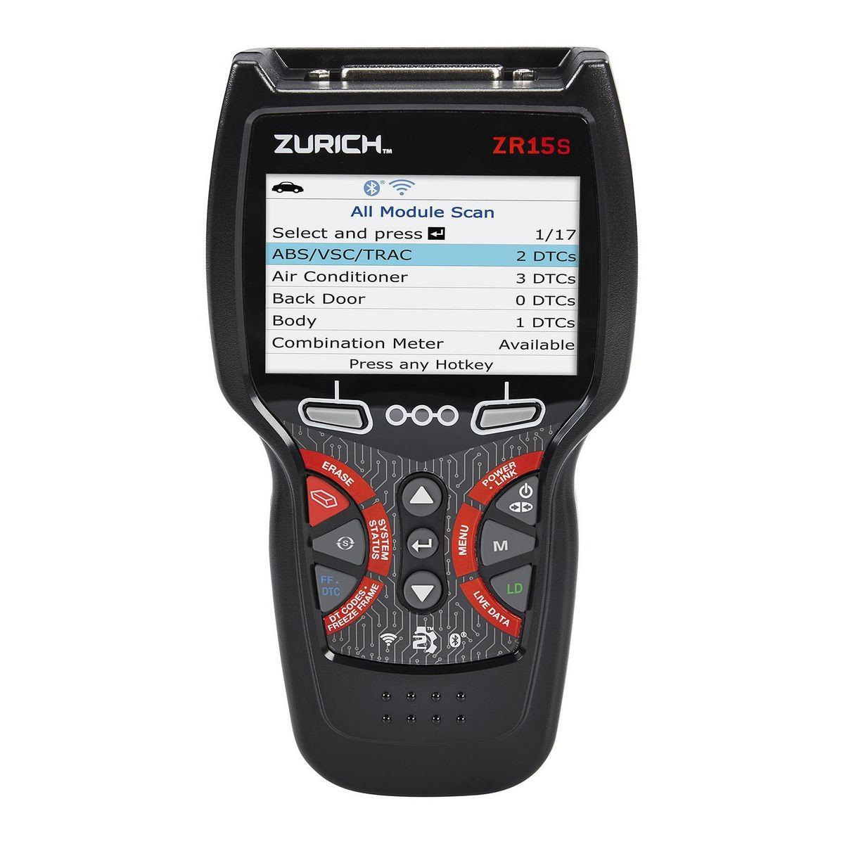
ZR15s OBD2 Code Reader with 3.5 In. Display and Active Test/FIXASSIST
Amazing deals on this Zr15S Active Test Obd2 Code Reader at Harbor Freight. Quality tools & low prices.
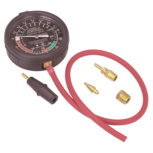
a vacuum and fuel pressure gauge is useful
learn to use the factory shop manual, and a multi meter and LISTEN to the engine closely, tapping and high pitch whines can indicate defective injectors or fuel pressure regulators, fuel pumps,mis- adjusted valve train components, worn distributor parts, check all the fuses and electrical grounds and corrosion on connections thats something thats frequently over looked etc. this process of finding the cause of a problem, is basically a detailed check list and once you understand what your looking at and what its supposed to do after each components tested, is basically a simple procedure if you test, and eliminating potential sources until you narrow it down to the cause, where you prove it then re-place, repair or adjust as required.
yes youll need to have some test equipment like, a shop manual, multi- meters and pressure gauges, timing lights etc. but its not that difficult.
RULE#1
never assume a damn thing ISOLATE ,TEST AND VERIFY
ANY TIME YOU SUSPECT FUEL INJECTOR OR FUEL SYSTEM RELATED ISSUES ,A REASONABLE START POINT IS TO USE A GOOD QUALITY FUEL INJECTION CLEANER ADDITIVE IN THE FUEL TANK AND SWAP TO A NEW FUEL FILTER
http://www.bgprod.com/catalog/gasoline- ... m-cleaner/
http://www.bgprod.com/catalog/gasoline- ... m-cleaner/
http://www.chevythunder.com/Flow chart index.htm
http://www.professionalequipment.com/ex ... ermometer/
having a good cross check tool like a quality IR temp gun, and a decent multi meter, sure helps find the truth as far as a defective gauge or sensor
http://chevythunder.com/
L98/ TPI Engine Start Sequence
When you start an L-98 engine Corvette, a series of events take place that causes the engine to run. Knowing the sequence will help you troubleshoot no start conditions.
Fuel Rail Pressurization:
When you first turn the key to the “on” position, the fuel pump will run for 2 seconds pressurizing the fuel rails. There is a Shraeder valve on the passenger side fuel rail near the rear of the engine and if you measure the pressure there after the pump runs, you should see between 40-42 pounds of pressure. The reading will go to 38-40 pounds nominal once the engine is running.
Initial Crank Action:
If you then rotate the key to the start position (assuming the anti-theft system has not disabled the starter), the engine will rotate.
Once the oil pressure has reached 4 PSI, the oil pressure switch will close allowing the fuel pump to run. (Note that you should have a black oil pressure switch/sender. It is mounted behind the distributor on the driver’s side and if it is not black, it is suspect due to a run of bad units that stayed in the GM parts pipeline for some time).
The distributor will send a string of pulses to the ECM (Engine Control Module) in response to the engine being rotated by the starter. These pulses continue as long as the engine turns (both starting and running) and if they are not present, the engine will not run.
ECM Reaction:
If the ECM sees oil pressure greater than 4 PSI and the reference pulses from the distributor, it will energize the injector drivers which will begin pulsing the injectors on for 4 ms (milliseconds) periods. (In the L98, all injectors on one side of the engine fire at the same time followed by all injectors on the other side firing at the same time. On the LT-1, the injectors are fired individually at the appropriate time).
The ECM will also pull in the fuel pump relay in effect paralleling it electrically with the oil pressure switch. (If the fuel pump relay fails, you can still normally get the car to start and run unless you can’t make at least 4 PSI oil pressure. This is a “limp home mode” feature put in place to allow for a fuel pump relay failure).
The ECM also monitors the TPS (Throttle Position Sensor mounted on the throttle body assembly) and wants to see .54 volts at this time. If it sees appreciably more than 0.54 volts, it will assume the engine is flooded and the driver has pressed the accelerator to the floor to clear the flooded condition and restrict the fuel flow as a result. (.54 volts during start and at idle from the TPS is very important to both starting and run performance.)
Assuming the ignition module is good (meaning there is a spark of sufficient intensity to ignite the fuel), the engine will “catch”.
Engine "Catches":
When the engine catches, the MAF (Mass Air Flow sensor mounted just ahead of the throttle body) sends a signal to the ECM advising that air is flowing and also just how much air is being pulled through to the intake manifold. The ECM takes note of the amount of air being consumed and adjusts the injector pulse width to around 2.2 ms nominally so as to attain a proper air/fuel mixture to insure combustion. (This is how the 1985 through 1989 L-98 works. For information on the 1990 and 1991 L-98 variant, see the Note below).
The engine should show an initial idle speed of around 900-1100 RPM and then slowly diminish to 600-700 RPM unless the air conditioner is on in which case it will run at around 800 RPM.
If this does not happen, the Idle Air Mixture valve (located on the throttle body) may be misadjusted. Alternatively, there may be a leak in the intake manifold or another vacuum leak may be present. Listen for hissing sounds---there should be none.
ECM Mode:
The engine will now be in Open Loop mode meaning that the ECM is controlling the air/fuel mixture by referencing values stored in memory.
Once the Oxygen sensor (mounted on the exhaust pipe) reaches operating temperature of several hundred degrees, the Manifold Air Temperature (MAT) sensor shows an intake air temperature of more than 140 degrees and the Engine Coolant Temperature (ECT) has reached 160 degrees, the computer will switch to closed loop mode meaning the Oxygen sensor’s output is examined along with the MAT and ECT outputs and the ECM adjusts the injector pulse widths (more “on time” or less “on time”) to constantly strive for a 14.7:1 air/fuel mixture which is the best mixture to hold down pollution.
Note that prolonged idling can force the computer back into open loop mode.
Note: In 1990, the MAF was eliminated from the engine in favor of a speed/density system. This system uses a sensor called the MAP sensor which measures the Manifold Absolute Pressure (hence the name MAP) and compares it with the atmospheric pressure outside the intake manifold. This information, coupled with the Manifold Air Temperature, Engine Coolant Temperature and Engine RPM is used by the ECM to determine the amount of air entering the cylinders. It is a different way of reaching the desired 14.7:1 air-fuel mixture ratio but functionally is like the MAF system in that the ECM uses the feedback to control the "on time" for the injectors.
Corvette used this approach in the 1990 and 1991 L-98 engines and in the 1992 and 1993 LT-1 engines. With the 1994 model C4, they went back to the MAF system. Note that MAF based systems are far more accurate since they measure air flow directly whereas the MAP system infers air flow indirectly. A multitude of things can throw the calculation off and Corvette returned to the MAF system beginning with the 1994 C4 (with a MAP backup). From a troubleshooting standpoint, the MAP operation comes into the sequence the same place that the MAF does.
Summary:
If you have a no start condition or if the L-98 starts and then dies, check the above items in sequence to see if all the events are occurring as required.
A Scan Tool makes this job much easier and is a highly recommended troubleshooting aid for these sorts of problems.
youll find a hour or so reading thru the links and sub links, on this site in the threads, will provide a great wealth of related info and incite into related factors, or the function or testing of sensors, that you may not currently be thinking about, or things that you might not think that are related to your issue that PROBABLY ARE
without testing your simply guessing
EFI works at higher pressures (a 1985-1991 TPI corvette as an example generally operates in the 38psi-42 psi fuel pressure range)
THINK,
fuel tank...to .fuel filter....to .-fuel pump....to feed into fuel rail& injectors. then out too....fuel pressure regulator...then too..return line to fuel tank
it might help if you think, fuel pump provides fuel flow volume,
fuel pressure is a measure of resistance to fuel flow,
the fuel pressure regulator acts as a valve that opens if the pressure exceeds about 42 psi (YES some versions like yours are manually adjustable) but the reason its there is to maintain a consistent 39 psi-42 psi to do that you allow the fuel pump to stack or pressurize fuel in the fuel rail and in theory the fuel pressure regulator only allows excess fuel volume to flow back to the fuel tank through the return line if that fuel pressure exceeds the 42 psi, the pump is designed to provide a bit more than the required 42 psi too insure fresh cool fuel is cooling the fuel pump while maintaining that consistent fuel volume at the fuel pressure, when you tromp on the throttle the flow of fuel drastically increases, the regulator momentarily restricts out going fuel to maintain the fuel rail pressure and volume, until the flow demand drops enough, for excess volume and the resulting increased pressure that results to open the regulator again,
WATCH VIDEO
https://www.youtube.com/watch?x-yt-ts=1 ... l=85114404
get out your shop manual and multi meter
if you suspect the injectors , you first use a multi meter to verify every injector reads the same ohms (usually near 11-16 okms, and yes they should all read very closely) then you need a noid kit for a G.M. fuel injection system, these are basically little lights that light as the injector pulse hits them that you plug into the injector harness,after you remove the harness from the injectors, they plug into the harness just like an injector, if you try to start the engine and they blink on and off the pulse is reaching the injectors thus proving that the injectors get the pulse
http://www.harborfreight.com/11-piece-n ... 97959.html
if you suspect the injectors have gone bad or are locked up and your test with a NOID LIGHT TEST KIT shows the injectors are getting the required pulse from the wiring and the injectors have the required ohms resistance and you have the fuel rail pressure, but your not getting fuel, and you are getting ignition spark,its always a case of isolate and test, that finds the cause, and you start with the basics of trouble codes , and fuel, compression, spark, and timing.
old school testing still works and if you swap the current injectors out for different injectors and nothing changes you have a good indication its not the injectors causing the problem, now the problem with that course of action is that new injectors tend to cost $300-$600 a set for 8 , thus a bit of creativity is used,
If it was my car Id have done a bit of research and located a list of cars that had compatible injectors that could be swapped in, then visit a salvage yard with a easily portable tool kit and a multi meter and found at least 16 injectors , that I could pull that passed the ohm meter test for use in testing the car, by simply swapping out the injectors wholesale after very carefully cleaning the salvage yard supplied injectors.(obviously the price will vary so ask before you go thru the effort but Ive generally paid $60-$80 for a set of 8 used injectors which I test with an ohms meter before I remove them, and having a spare set is certainly worth that)
heres a link to swapping injectors
http://www.thirdgen.org/injectorswap
read thru these links
AND YES AMAZINGLY, ACTUALLY READING THRU THE POSTED LINKS AND SUB LINKS might help
http://members.shaw.ca/agent86/Fuel Control And Delivery-8A.pdf
http://members.shaw.ca/corvette86/EngineCranksButWontRun.pdf
http://members.shaw.ca/corvette86/FuelSystemDiagnosis.pdf
http://members.shaw.ca/corvette86/No-Service Engine Soon - Light.pdf
http://members.shaw.ca/corvette86/SES Light On Steady.pdf
http://members.shaw.ca/corvette86/Non Scan Diagnostic Circuit Check.pdf
http://members.shaw.ca/corvette86/Engine to ECM Wiring Diagram 86.pdf
http://members.shaw.ca/corvette86/Component Location View 86.pdf
viewtopic.php?f=80&t=1470&p=3304#p3304
http://members.shaw.ca/corvette86/FuelSystemDiagnosis.pdf
http://www.youtube.com/watch?v=49WXmzfO ... e=youtu.be
http://forum.grumpysperformance.com/viewtopic.php?f=32&t=596
http://forum.grumpysperformance.com/viewtopic.php?f=32&t=2697
http://garage.grumpysperformance.co...questions-can-be-found-here.12892/#post-66934
http://forum.grumpysperformance.com/viewtopic.php?f=32&t=1401
if its blowing fuzes , or some components not working that did previously,somethings changed, theres frequently a bad ground , loose connection, corrosion,or a short some place,in the wiring or a defective sensor, that needs to be located,and isolated then corrected, pull the trouble codes and use the meter to check amps, ohms and voltage and verify all sensors, the shop manual has wiring diagrams
http://forum.grumpysperformance.com/viewtopic.php?f=80&t=728&p=9217&hilit=sensor+ohms#p9217
http://forum.grumpysperformance.com/viewtopic.php?f=52&t=4410&p=11602&hilit=propane+leaks#p11602
http://forum.grumpysperformance.com/viewtopic.php?f=44&t=882&p=1390&hilit=propane+leaks#p1390
http://forum.grumpysperformance.com/viewtopic.php?f=32&t=168
http://forum.grumpysperformance.com/viewtopic.php?f=32&t=1401
http://www.corvettephotographs.com/c4vettes/codes.htm
http://www.corvettephotographs.com/c4ve ... launch.htm
WHEN TESTING<be sure the fuel pressure gauge reads correctly by comparing it to a second test gauge, these fuel pressure gauges are frequently defective
http://www.harborfreight.com/fuel-injec ... 92699.html
this cheap fuel pressure test gauge works ok, you just need to figure out how to tap into the fuel rail or line and that varies between years but certainly not a difficult issue to either remove a shrader valve and insert an adapter barb fitting or splice a TEE into a fuel line as a temp. test point, certainly any mechanic has an assortment of the common barb fittings required in a test kit
THE CHEVY shop manual will probably cost less than the trip to the dealership if you don,t and its useful life will far exceed that trip also!
first check your shop manual for the fuse and fuse able link locations
fuses are located in several locations and fuse-able links near the battery
STEP ONE IS ALWAYS GET A FACTORY SHOP MANUAL, AND READ THE LINKS BELOW
Verify fuel pressure,. by using a fuel pressure gauge on the shrader valve on the fuel rail, with a pressure gauge,
Verify injector pulse by using a noid light, & spark at the plugs by using a spark tester.
verify timing with a timing light
pull the trouble codes and check all fuses
CHECK ALL YOUR FUSES WITH A MULTI METER
MAF Problems
Faulty MAF sensors will normally light the check engine light on the drivers information center if the problem is constant and store a trouble code. If intermittent, a trouble code will still be stored as long as the battery is not disconnected.
Normally, the problem is a poor connection at the sensor and wiggling the wires, unplugging and reinserting the connector will often cure the problem.
A faulty MAF will normally cause a no start or difficult start condition and although you can eventually get the car into the "limp-home" mode in most cases, you need to attend to the problem ASAP.
AC/Delco sensors can become intermittent or give false readings if the wires become contaminated as explained above.
The MAF is a critical part of the emission control system and as such will cause the computer to react to problems very quickly, setting trouble codes and reducing performance in ways that cannot be ignored for long.
MAF Mods
The Bosch MAF is often modified by removing the two screens that are present in the front and rear of the cylinder. Removing these screens significantly increases the air flow through them and this results in more horsepower. Removing the screens is an old trick from the Corvette Challenge days in 1988 and 1989. It does work but is illegal in many states so be advised not to do anything that will get you arrested for a pollution violation.
The AC/Delco MAF is not readily modified. It is what it is but since it is a larger diameter than the Bosch, it responds well to changing the air filter to a free flowing type such as the K&N filter."
http://www.mamotorworks.com/corvette-c4 ... 6-893.html
http://content.mamotorworks.com/pdf/601096.pdf
1985 fuel pump relay
probably 80% of the small screw-ups like your experiencing (and your not alone everyone has those screw-ups , adjustments and programing glitches or problems with their car) that can be corrected with a few minutes reading and carefully following directions with a shop manual.
a few tests and getting the facts before you start throwing parts at a problem,beats guessing every darn time, keep in mind,wet, loose, or broken electrical connectors or corrosion on connectors, is also possibly a cause of intermittent problems
If youve got an early year TPI , thats designed to use a 9th cold start injector,check the cold start injector as its a potential problem source if its not working correctly.The cold start injector is between the front and rear pairs of runner tubes on the driver-side.on early TPI engines if its not working or loose causing a vacuum leak starting the engines much harder, later versions did not use these
if you have at lease 38 psi in the fuel rail, and it holds at or near at least 38 psi for at least a couple minutes after you stop cranking the engine, the fuel pressure regulator is most likely functioning correctly, but you state the injectors are not squirting fuel and the pump keeps running while you crank the engine?
you can test the electrical connectors on the injectors with a noid test light to watch the electric pulse,at each injector location, ID verify timing injector resistance,and check for vacuum leaks while testing, and remember theres a 9th cold start injector on the 1985-88 TPI fuel rail
the CORRECT ANSWER to what the cold start injector looks like that I get asked rather frequently, depends on what year, TPI you have, this is the early version like on the 1985 and it takes a unique injector, and its no longer available from chevy. they are also well know sources for vacume leaks
Almost every one of those OEM fuel rail & fuel line set ups ON A TPI OR LT! has by this time had some damage and almost all of them work and function reasonably well in spite of what is more than likely mostly cosmetic rather that true mechanical damage in that its un-likely to significantly restrict fuel flow
verify the fuel pressure with a fuel gauge connected to the shrader valve on your TPI fuel rails,
GM part number for the complete fuel rail o-ring kit is 17111696
if your TPI FUEL PRESSURE REGULATOR DIAPHRAGM LEAKS youll find it difficult or impossible to be starting your car
heres a link to the correct o-rings they are light blue
NAPA sells them at times
all the o-rings on the fuel rails and injectors need to be dipped in thin oil so they insert and slide into place with less friction, this tends to greatly reduce the chance of the o-rings ripping, and yes you need the correct o-rings that fit correctly to begin with if you expect the rings to seal correctly
http://tpiparts.net/inc/sdetail/10950/300
17113544 - Injector Seals
17111696 - O-Ring Kit
22514722 - Fuel Inlet O-Ring
22516256 - Fuel Inlet O-Ring
The above part numbers provided me with all of the seals shown below circled in red. I would recommend that you replace these seals whenever you service your TPI system. Remember, you've got gasoline under about 45 pounds of pressure flowing through the fuel rails etc. A leak could easily catch fire and cost you your car.
RELATED THREADS
9
STOCK TPI,LTI,LSI ENGINES USE HIGH IMPEDANCE INJECTORS
these links provide a great deal of useful info, so take the effort to read thru them
http://members.shaw.ca/corvette86/FuelS ... gnosis.pdf
http://fuelinjectorconnection.com/shop/ ... ductid=202
knowing whats going on and WHY can help
http://www.corvettefever.com/techarticl ... index.html
http://members.shaw.ca/corvette86/Component Location View 86.pdf
http://members.shaw.ca/corvette86/FuelSystemDiagnosis.pdf
this flow chart above helps, the book below has the wiring diagrams
http://www.themotorbookstore.com/corvet ... ction.html
http://www.mamotorworks.com/corvette-c3 ... 6-891.html
http://www.mamotorworks.com/corvette-19 ... 6-900.html
http://www.autostalk.com/corvette/mass- ... ost2521803
http://www.corvettefever.com/techarticl ... index.html
http://www.rollaclub.com/faq/index.php? ... uel_System
http://www.enginebuildermag.com/Article ... stems.aspx
viewtopic.php?f=32&t=764
http://www.centuryperformance.com/fueli ... g-140.html
http://www.centuryperformance.com/fuel- ... g-141.html
YOU REALLY NEED THIS INFO
http://chevythunder.com/
KNOWING WHAT YOUR DOING IS IMPORTANT, TO GETTING GOOD RESULTS!
no one knows everything about all models and years so it helps to have the correct procedures and info in a handy reference source,now you can get by with a HAYNES or CHILTON'S manual, or something similar, but for detailed info, OWNING the CHEVY SHOP MANUAL FOR YOUR SPECIFIC CAR IS ALMOST MANDATORY!
I get asked frequently, "how did you know how to do that?"
well, EXPERIENCE plays a big roll, working on similar cars and engines helps, and the INTERNET is a good resource... but theres ALWAYS a big need for DETAILED REFERENCE MATERIAL, SPECIFICALLY MATCHING YOUR PARTICULAR CAR and if you have not yet invested in a SHOP MANUAL for the year make and model of you pride and joy muscle car your either not serious about your hobby, or most likely NOT A SERIOUS HOT RODDER! I constantly see guys SCREWING up installations, or adjustments,if you don,t know exactly what your doing, you need to either let the dealer do it and PRAY his mechanics are experienced and can read, OR..if your like ME, you would rather do it yourself and KNOW its been done correctly...
if your not aware, heres where to order them....
1-800-782-4356
http://helminc.com/helm/homepage.asp?r=
your average shop manual may cost $100-$150 ONCE! but you'll easily save far more than that in reduced time and screw ups in under a years time or in many cases on one job vs having the dealer do the work!
IF YOU DON,TY HAVE A FACTORY SHOP MANUAL FOR YOUR CAR YOUR WORKING AT A DISADVANTAGE
http://www.helminc.com/helm/welcome_sel ... M2S049ETF8
this info may help
http://www.corvettebuyers.com/ecm.html
http://www.aldlcable.com/
don,t forget to pull trouble codes in your search for answers
Last edited by a moderator: