how your cam LSA effects your compression ,torque , DCR

grumpyvette

Administrator
Staff member


lsadig.jpg


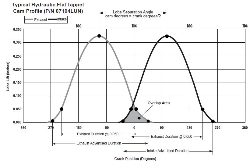
TIGHTER 104-110 LSA tend to increase scavenging efficincy but at the cost of less smooth idle
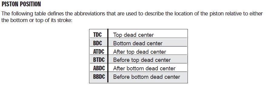
pistonposition2.jpg

2016-02-26_16-51-06.jpg

LSA lobe separation angle is locked into the cam when its ground and can not change, if its ground at 110,degrees or 114 degrees it will stay that figure
and

LCA lobe center angle, can be changed
if you advance the cam 4 degrees both the intake and exhaust lobe opening and closing points open and close 4 degrees earlier.
if you RETARD the cam 4 degrees both the intake and exhaust lobe opening and closing points open and close 4 degrees later.
LSAChart01.jpg

USE THE CALCULATORS
http://www.rbracing-rsr.com/runnertorquecalc.html
http://www.wallaceracing.com/chokepoint.php
http://www.wallaceracing.com/header_length.php
http://www.wallaceracing.com/chokepoint.php
http://www.rbracing-rsr.com/runnertorquecalc.html
http://www.velocity-of-sound.com/velocity_of_sound/calculator1.htm


READING THESE RELATED LINK'S WILL HELP
http://garage.grumpysperformance.com/index.php?threads/cams-explained.324/

http://garage.grumpysperformance.com/index.php?threads/camshafts-8-lessons.5154/

http://victorylibrary.com/mopar/cam-tech-c.htm


http://garage.grumpysperformance.com/index.php?threads/oil-stained-intake-runners.14209/#post-72145
pistonposition4.jpg


lsadig.jpg

lclcomp.png
camcomp.jpg

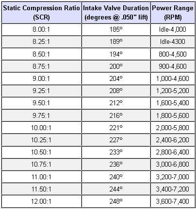
the chart above can be used as a rough guide to match cam duration at .050 lift and static compression in engines obviously other factors come into play so its only a rough guide

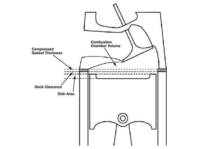
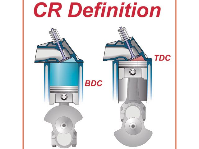
OK, first fact! the piston can,t compress anything until both valves fully seat, static compression is based on the volume compressed between the piston starting at bottom dead center and compressing everything into the combustion chamber , head gasket quench,volume, that remains when the pistons at TDC

there are quite useful ,cam selection soft ware programs that get you in the ball park, but the final selection is based on far more factors than most of those software programs address
http://http//www.camquest.com/ http://www.camquest.com/


http://www.cpgnation.com/forum/threads/... ngle.2406/


http://www.wallaceracing.com/camcalc.php

http://www.wallaceracing.com/Calculators.htm
http://garage.grumpysperformance.co...ng-cam-and-shifting-the-lca.10553/#post-44949

http://garage.grumpysperformance.co...et-it-to-last-cam-install-info.90/#post-57942
camtimebush.png

lobe_diagram_lg.jpg


cpr2.jpg

definition.jpg

compress_06.jpg
index.php

quenchjj.jpg

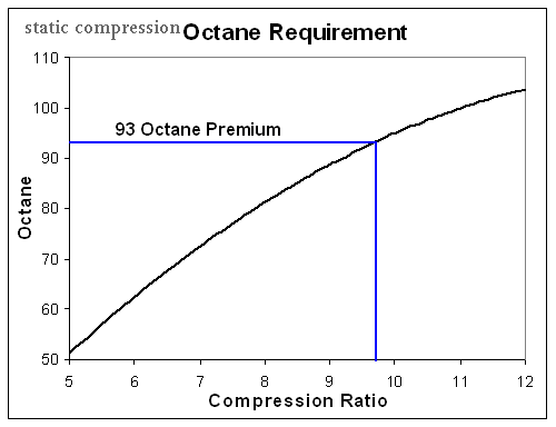
Octane_Requirements.gif

0311phr_compress_07_z.jpg

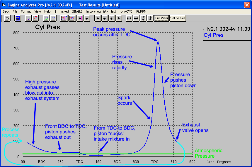
Cylinder-Pressure-lLrg.gif

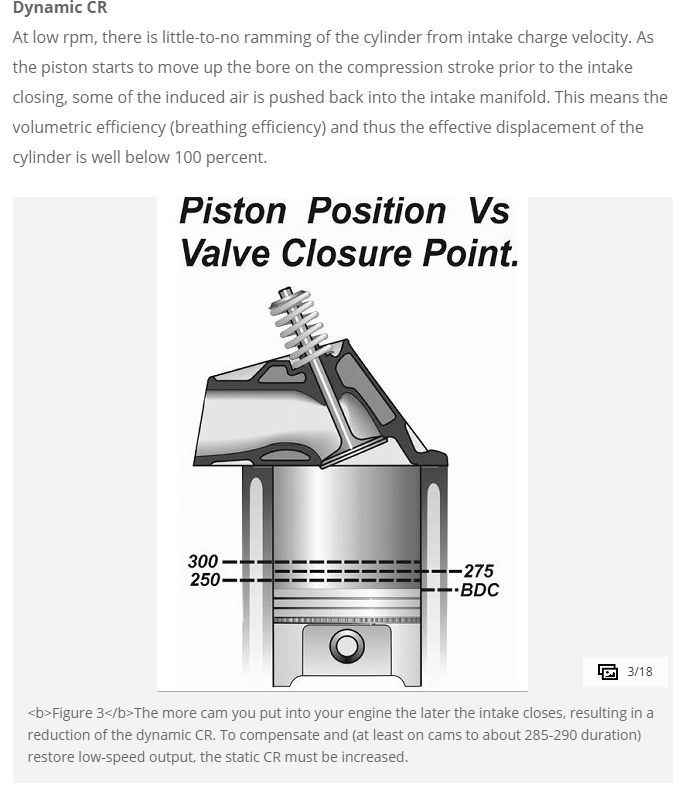
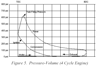
dynamic compression is the ONLY compression the engine ever sees or deals with, it measure compression from the time both valves seal the chamber,and that is always lower simply because the valves always seat after the piston is already moving upwards on the compression stroke.
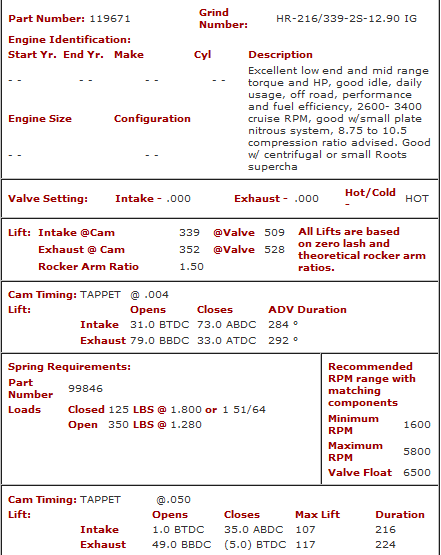
crane119671.png

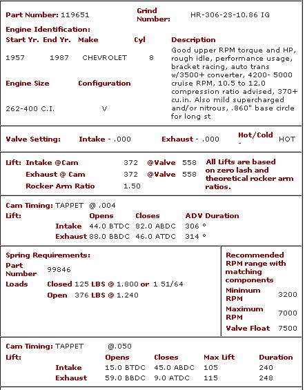
if we look at the crane cam I linked earlier you see the valves seat at about 75 degrees after bottom dead center

RELATED INFO YOU MIGHT NEED


Lobe Separation Angle (LSA) is NOT the same as Lobe Centerlines (LC), although the two are directly connected.
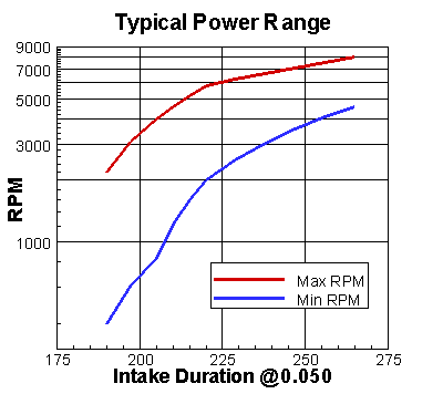
craneq2.gif


keep in mind that the piston moves a great deal slower per degree of rotation
near the top and bottom of the stroke than it does near the mid stroke in the bore, so thers more time for flow and presure to build per degree of crank rotation,making those areas of rotation more critical to performance
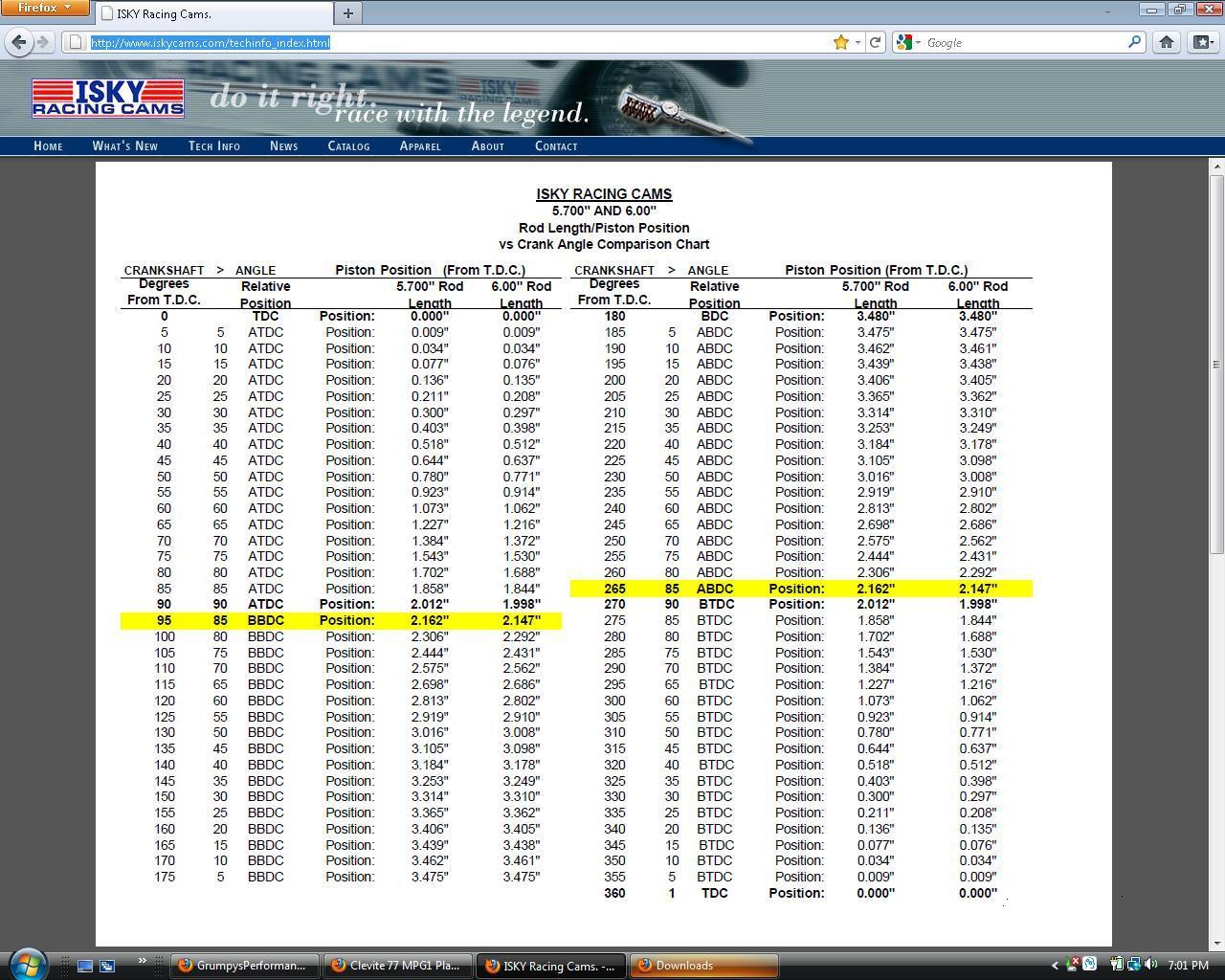
iskypistonloc.jpg


lobeang.png

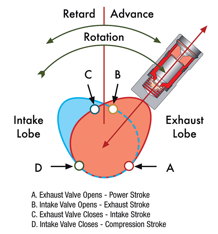
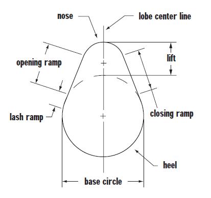
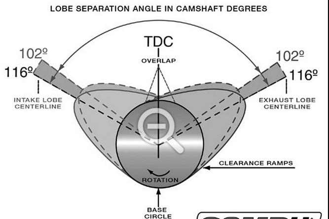
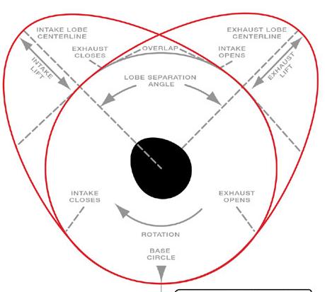
The Lobe center Angle is measured as the degrees that the crankshaft rotates BETWEEN the exhaust valves maximum lift point (aka: Exhaust Centerline) and the intake valves maximum lift point (aka: Intake Centerline). Check the lead illustration in this story from COMP Cams to show this effect. The highest lift points on the lobes are referred to as the cam œLobe Centerlines and are usually ground somewhere between 102 and 122 crankshaft degrees. Since Lobe Centerline is referenced in relation to crankshaft degrees as well, it can be moved around, depending on where you install the cam.
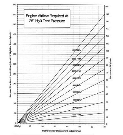

low07_zooma.jpg


When you degree the cam, youre usually checking to see if it s installed at the cam manufacturer™s recommended Intake Centerline point. Lets say your cam manufacturer recommends installing the cam at a 112-degree Intake Centerline. Using the degree wheel you check the intakes highest lift point to be exactly at 112-degrees. That means youve now installed the cam Straight Up . If the degree wheel shows an intake max lift point of 110-degrees, the cam is now INSTALLED 2-degrees advanced from the manufacturer s settings. If the degree wheel showed an installed position of 114-degrees, the cam is now INSTALLED 2-degrees retarded.

Lobe Separation Angle, on the other hand, is ground into the cam and it cannot be changed (see red arc in illustration). To check your LSA you calculate it by adding the intake and exhaust Lobe Centerline figures together and dividing their sum by two (Ex: 112 intake Centerline + 116 exhaust Centerline = 228 / 2 = 114-degree LOBE SEPARATION ANGLE).


There s more. These are also the figures used to indicate how much the cam s intake lobe was ground advanced or retarded from the factory. To find intake lobe advance/retard, simply subtract the Intake Lobe Centerline from the Lobe Separation Angle (i.e.: LSA 114 IC 112 = 2-degree advance). This difference is how far advanced or retarded your cam was ground at the factory, 2-degrees in our example here. You cannot change Lobe Separation Angle because it is ground at the factory. But you can advance or retard the cam in relation to the crank when itâ s degreed-in."

"EXAMPLE, OF A
very common mis- conception, is that a cam which is ground on a 108 degree lobe center. which has more overlap and will reduce your DCR due to greater overlap."

PROBABLY one of the MOST COMMON MYTHS
( is that overlap with a tight LSA bleeds off compression)
Overlap has nothing to due with DCR. A cam with 108 LSA will close the intake valve sooner on the compression stroke and create MORE cylinder pressure than a cam with 112 LSA. That assumes durations and cam lobe designs are the same of course "

this is correct

example
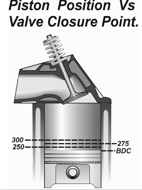
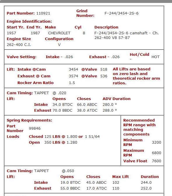
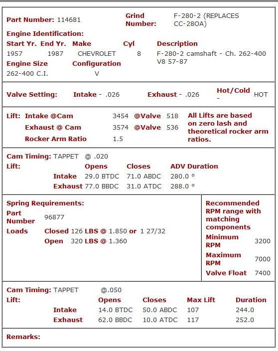
LOOK heres TWO cams WITH IDENTICAL DURATION EXCEPT FOR THE LSA,(LOBE SEPARATION ANGLES) assuming both cams are installed with identical LCA (LOBE CENTER LINE ANGLE)remember lobe center angles can be changed thru indexing the cam when degreeing it in, LSA is ground into the cam during manufacture, the tighter LSA of the crane 110921 builds a bit more cylinder pressure, AS THE VALVES CLOSE ABOUT 5 degrees earlier (ABDC AFTER BOTTOM DEAD CENTER)

110921 intake valve closed at 45 degrees after bottom dead center
114681 intake valve closed at 50 degrees after bottom dead center

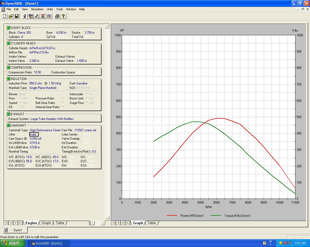
and results in slightly more torque over a NARROWER rpm band so its better with a manual transmission, the crane 114681 with its wider LSA tends to work better with an auto trans with its wider torque band but very slightly lower peak torque, the crane 110921 has more overlap and better savaging in the mid rpm band, but it idles rougher at low rpms and that overlap doesn,t help if you use nitrous
COMPARE the TIMING
110921.jpg

110921q.jpg

narrower LSA, more overlap & more effective compression, because the intake valve closes earlier
114681.jpg

114681q.jpg

wider LSA, less overlap & less effective compression, because the intake valve closes later
dcr.jpg

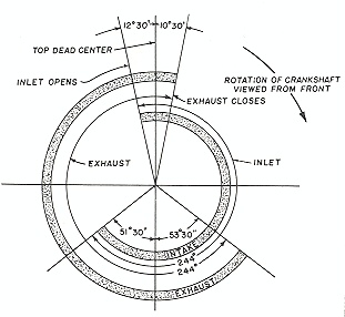
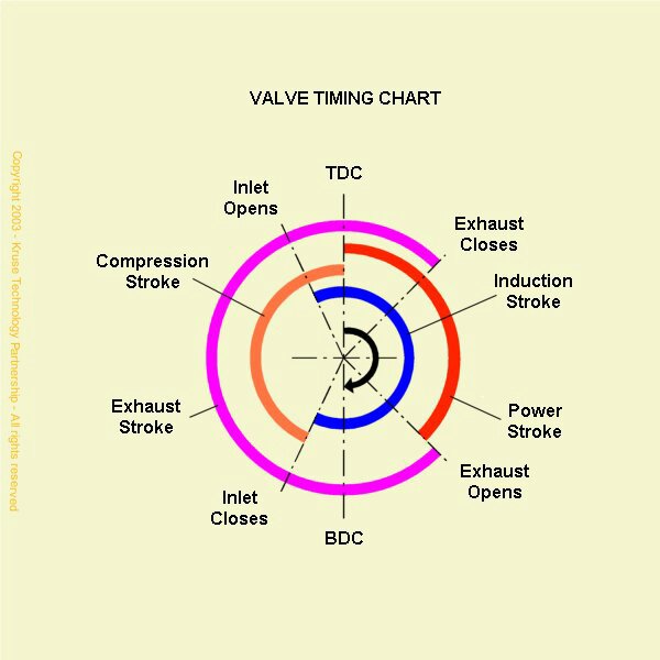
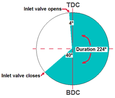
when your reading a cam spec card, you'll want too keep in mind theres 720 degrees in a cycle and the cam turns at 1/2 the speed of the crank so the piston reaches TDC twice in one complete rotation of the cam, plus cam cards generally start with the exhaust valve opening not the intake valve as most of us might assume

http://www.projectpontiac.com/ppsite15/ ... calculator

while all cam timing figures will varry this might help
Second_zps26c385d0.png

Third_zps80758035.png

Fourth_zps0f8ce983.png

READ THREAD


Valvetime.jpg


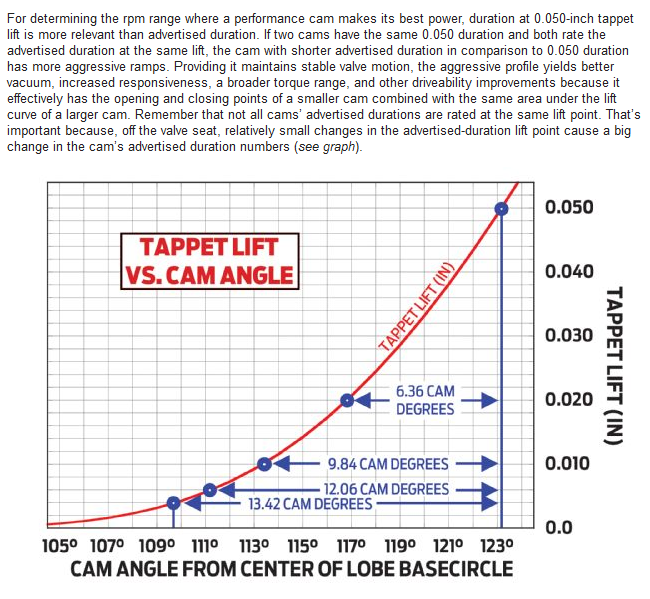
Fig5LiftCurve_HydSolidRoller800.jpg


USING THE .050 LIFT figures, notice that the tighter LSA (LOBE SEPARATION ANGLE)cam CRANES 110921 has the intake close at 45 degrees ABDC while the wider lsa CRANES 114681closes the valves at 50.0 ABDC (the wider LSA results in the valve closing 5 degrees later on the pistons compression stroke, effectively reducing the effective compression ratio
The quickest, and most accurate, way of finding ICL :
1.--Install dial indicator on top of retainer.
2.--Turn to max valve lift.
3.--Zero dial indicator.
4.--Turn engine backwards to -.100 drop on indicator.
5.--Turn engine forwards until indicator reads -.050.
6.--Record this in degrees ATDC.
7.--Continue turning engine over max valve lift until indicator reads -.050 down on closing side of intake.
8.--Record this too as degrees ATDC. It should be close to, but before, BDC.
9.--Add the 2 readings ATDC, then divide by 2. This is the ICL.
10.-Advance the cam with a button to where you want it to be.
11.-Repeat all steps to verify the cam is where you want it to be.


tight 108 LSA
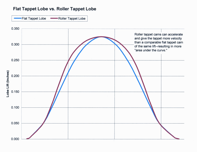
FlatVsRollerChart.gif

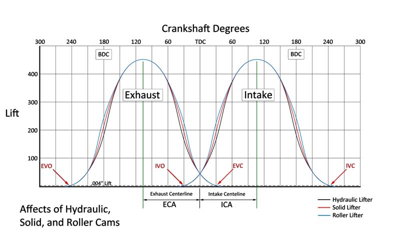
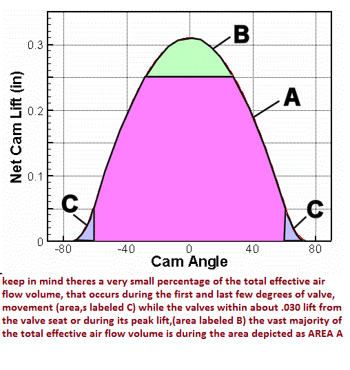
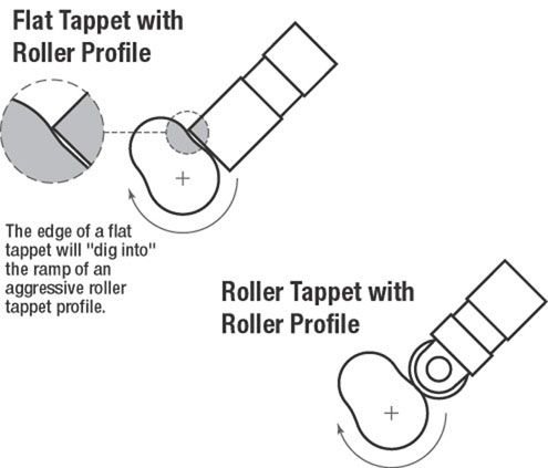
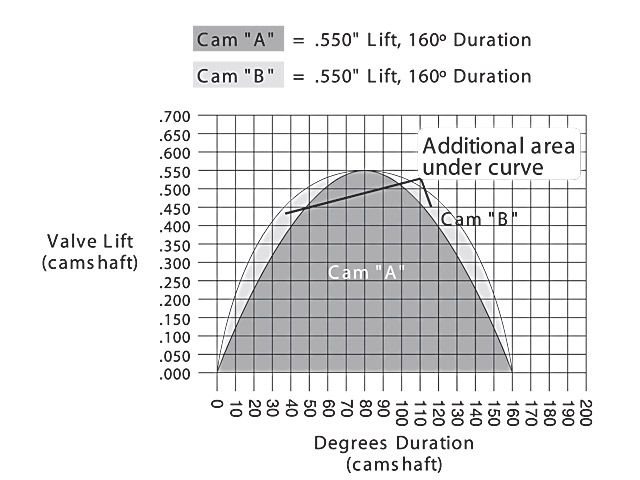
notice its right where the roller cams lobe design maximized the extra air flow potential that is the most effective flow area during the whole valve flow curve
and yes it frequently helps to match a roller cam to roller rockers as the reduced friction further helps the engines durability and ability to easily cope with faster valve train component acceleration, that tends to reduce heat and wear.
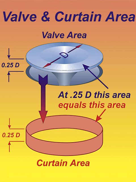
The following equation mathematically defines the available flow area for any given valve diameter and lift value:
Area = valve diameter x 0.98 x 3.14 x valve lift
Where 3.14 = pi (π)
For a typical 2.02-inch intake valve at .500-inch lift, it calculates as follows:
Area = 2.02 x 0.98 x 3.14 x 0.500 = 3.107 square inches, thus it makes a great deal of sense to push the valve lift a bit over .500, and have an intake port that is at least 3.2 square inches in cross sectional area, if you want to maximize flow on a 2.02" intake valve
porting+valve_area.jpg


LiftCurveAread.gif


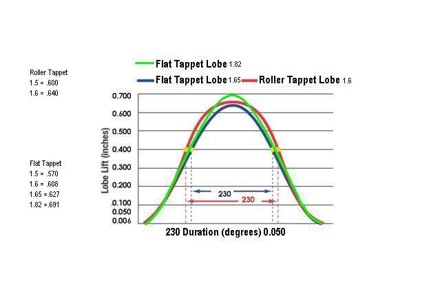
http://garage.grumpysperformance.co...-the-extra-cost-vs-a-flat-tappet-design.3802/
FlatTappetVSRollerTappet6.jpg


wide 114 LSA


http//users.erols.com/srweiss/tablehdc.htm [URL][URL][URL][URL][URL]http://users.erols.com/srweiss/tablehdc.htm[/URL][/URL][/URL][/URL][/URL]

http://www.enginebuildermag.com/Article ... teria.aspx


http://www.lunatipower.com/Tech/Pistons ... eight.aspx


http://www.hotrod.com/techarticles/engi ... z2FeQk91VU

aluminum cylinder heads tend to allow you to run about 1/4-to-1/2 point more effective compression, IE, if iron heads get into detonation at 10:1 ALUMINUM might ALLOW YOU TO RUN 10.3-10.4:1 BEFORE GETTING INTO DETONATION, BUT ON THE PLUS SIDE AT LEAST IN THEORY IRON HEADS AT ANY GIVEN CPR WILL HAVE A SLIGHT ADVANTAGE IN HP
but in my real world testing the difference is much closer almost non-existent
the main advantage I see in aluminum heads is lighter weight and their much easier to repair when damaged
an aluminum cylinder head allows heat transfer to the engine coolant at a significantly higher rate than an iron head, and generally about .25-.50 higher compression can be tolerated but theres No absolute real definite answer, depends on quench, cam LSA, cylinder head design, advance curve, fuel/air mixture, intake temperature, coolant temp, spark plug design, piston design, heat barrier coatings, combustion chamber surface texture, and a bunch of other parameters.

[URL][URL][URL]http://www.iskycams.com/ART/techinfo/ncrank1.pdf[/URL][/URL][/URL]


here's a cam timing chart to use with it

http://www.crower.com/valve-timing-chart

http://www.amotion.com/tech/camselect.html

http://www.auto-ware.com/calcs/sep_adv.htm

http://www.projectpontiac.com/ppsite15/ ... calculator ]

READ THRU THESE CAREFULLY
http://www.compcams.com/Community/Artic ... 2026144213


http://www.enginebuildermag.com/2016/02/theres-no-simple-formula-to-choosing-the-perfect-camshaft/

http://www.popularhotrodding.com/tech/0 ... index.html

http://www.hotrod.com/techarticles/113_ ... index.html

http://www.circletrack.com/techarticles ... ation.html

http://www.popularhotrodding.com/tech/0 ... index.html

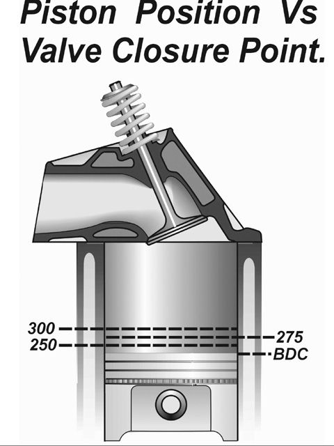
showing degrees of rotation and piston position, as you can see the valve on the wider LSA closes 5 degrees later on the wider LSA and the piston can,t compress ANYTHING until both valves are closed, the tighter LSA allows the piston to compress almost a tenth of an inch more cylinder volume, you'll find the tighter lca usually makes more low and mid rpm power , and in many cases more peak power but has a slightly rougher idle and the power peaks faster in the rpm curve were not talking a huge change, maybe 7-8 hp/ft lbs but the tighter lca tends to lope more, idles rougher and be more responsive, keep in mind that if you had selected a cam with 5-7 degrees more duration on the wider lca the overlap would be similar, but the effective compression would be even worse

as a general guide you want to get the valve open to well above the 1/4 of the valve diam. to maximize the potential flow as quickly after TDC as physically possible and hold it open as long as possible if you want to maximize the cylinder volumetric efficiency, but obviously factors like exhaust scavenging and compression and the cars gearing and the need to run well over a wide rpm range preclude, maximizing efficiency in a single narrow power band in most applications
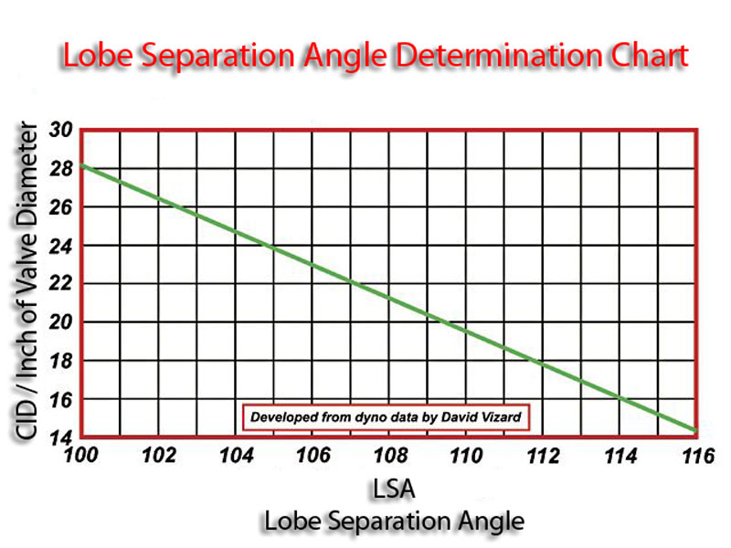
LSAChart01.jpg

valve seat and back face angles ,valve diameter and valve lift and duration effect the flow thru the curtain area

from an old Hot Rod Tech article with this comment from Joe Sherman:

“Fully assembled, the engine's static compression ratio came in at 11.02:1. Yikes! Compression is good for making power if the engine doesn't get into detonation, but at first glance, this high a ratio seems excessive for an iron-headed engine on 91-octane. However, with the big-overlap cam, cranking compression was only 182-185 psi, well within Sherman's comfort zone. In his experience, anything less than 200 psi is permissible for running a small-block Chevy successfully on pump gas. And in fact, running 91-octane, the engine would make its best numbers with 36 degrees of total advance with no evidence of detonation using NGK UR6 plugs gapped at 0.039 inch.”

keep in mind that valve may be forced off its seat, too full lift and re-seating 50 plus TIMES A SECOND at near 5500 rpm, so theres very little TIME for gases to move through the very restrictive space between the valve seat and valve edge
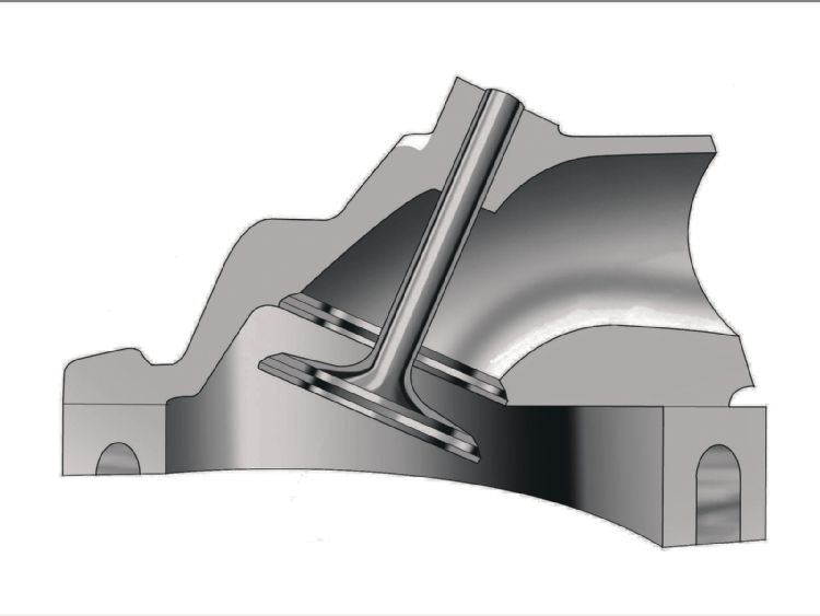
vgd4.jpg

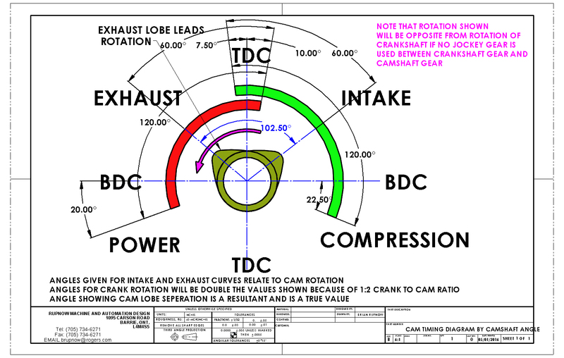
Calculating the valve curtain area
The following equation mathematically defines the available flow area for any given valve diameter and lift value:
Area = valve diameter x 0.98 x 3.14 x valve lift
Where 3.14 = pi (π)
For a typical 2.02-inch intake valve at .500-inch lift, it calculates as follows:
Area = 2.02 x 0.98 x 3.14 x 0.500 = 3.107 square inches

porting+valve_area.jpg

CAM%20TIMING%20DIAGRAM%20BY%20CAMSHAFT%20ANGLE.jpg


tsm-fig10.jpg

wpid-valve_timing_chart.jpg


pistonposition1.jpg

pistonposition2a.jpg

LiftCurveAread.gif

on the street youll almost always find that the lower duration cam in the choice between two similar cams will in the long term be a slightly more useful choice.
(the simple reason why is that most street cars spend the vast majority of the time operating well below 4500-5000 rpm, and lower and mid rpm torque not peak hp is used far more often) it hardly makes sense to build any engine to produce its peak power in the rpm range you,ll rarely use. and the extra duration will generally reduce the low and mid rpm torque you use the vast majority of the time, in exchange for a bit more peak power you'll rarely access.

camcomp.jpg

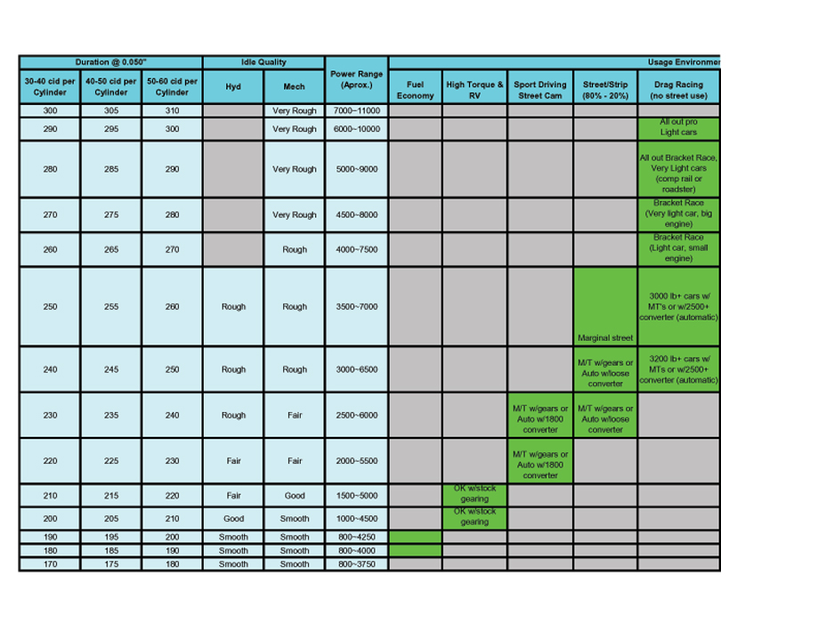
heres a chart I found that I don,t fully agree with, I think its a bit conservative, by about 3%-5% on the required cam duration ,required to avoid detonation with todays crappy octane fuel, but it at least gives you a base to work from, but Id suggest selecting a bit more duration
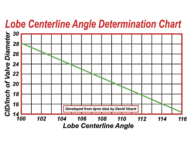
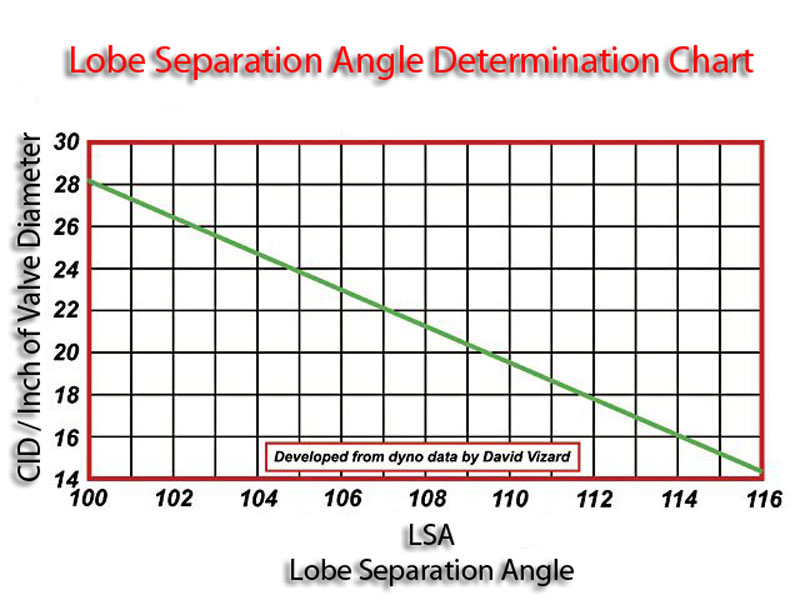
combining the info posted a 383 sbc has 47.8 cubic inches per cylinder divided by 2.02=23.7 on the chart above, so youll find cams in the correct duration range having a tight 105-108 lSA most efficient at filling the cylinders in many combos,

lets say we build a 496 big block with 2.19" intake valves,
496 divided by 8=62 cubic inches per cylinder, divided by 2.19=28.3. now look at the chart! you find youll need a rather tight 101-103 LSA
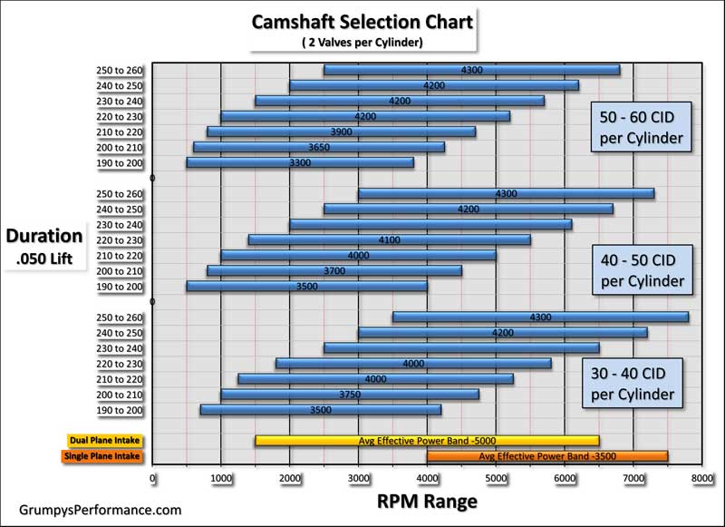
Duration_v_RPM-Range_wIntakeManifold01.jpg


camlobesfig.jpg


http://www.hotrod.com/techarticles/113_ ... ology.html
"LOBE SEPARATION ANGLE: This is the relationship between the centerlines of the intake and exhaust lobes. A 110-degree lobe separation angle means that the peak opening points of the intake and exhaust lobes are 110 degrees apart. This is ground into the cam and can't be changed without changing cams. Lobe separation angle is another way of expressing overlap, which is the term formerly used by cam manufacturers. Overlap is the amount of time that both valves are open in the same cylinder. When both valves are open at the same time, cylinder pressure drops. A cam with 106 degrees of lobe separation angle will have more overlap and a rougher idle than one with 112 degrees, but it'll usually make more midrange power."

ok first some facts
the valves reach max lift at a time when the pistons not even near TDC

heres a typical cam timing on a good hydraulic roller cam for a SBC that IVE used frequently


heres a cam timing chart


http://www.crower.com/valve-timing-chart


heres a crank rotation and piston angle chart

http://www.iskycams.com/ART/techinfo/ncrank1.pdf


simple math shows the intake valve reaches max lift near 118 degrees atdc
when the pistons about 3" down the bore
the exhaust reached max lift while the exhaust valve and piston were also reasonably far apart or almost 2.5" down the bore , valves tend to come closest to pistons at about 10- 20 degrees before or after TDC while not nearly at full lift and the duration and LSA of the cam had far more effect than max lift

read this


read thru these sub links


http://www.hioutput.com/tech/343hp/343hp.html


(if your stuck using restrictive heads, follow this build and use much of what can be used as its designed to maximize restrictive heads)


http://www.webcamshafts.com/pages/cam_glossary.html


http://www.thirdgen.org/sbc-camshafts-primer


http://www.popularhotrodding.com/tech/1 ... index.html

http://www.popularhotrodding.com/tech/0 ... index.html

http://www.compcams.com/Community/Artic ... 2026144213


ERSON, http://www.pbm-erson.com/Catalog/Erson/Camshafts
ISKY, http://iskycams.com/cart/index.php
HERBERT, http://www.herbertcams.com/herbert-cams-cam-kits/
CROWER http://www.crower.com/camshafts.html?cat=854
ENGLE, http://www.englecams.com/
LUNATI ,http://www.lunatipower.com/Performance-Cams.aspx
HOWARD CAMS ,http://www.howard
CLAY SMITH CAMS, http://www.claysmithcams.com/camshafts/scams.com/
crane (386)310-4875

crower 619.661.6477

erson 800-641-7920

lunati..662-892-1500

ISKY 323.770.0930

clay smith 714-523-0530

http://www.compcams.com/Technical/TimingTutorial

http://www.circletrack.com/techarticles ... ation.html

800-615-ValveTimingIllustration-002.gif


Separating the Cam Issues
LSAChart01.jpg

Fig5LiftCurve_HydSolidRoller800.jpg

By Mike Petralia


http://www.cartechbooks.com/vstore/show ... 4&CATID=21
Camshaft Lobe Separation Angle Matters

When finding the perfect cam for a street engine, Lobe Separation can help do the trick. Could you take two cams that are ground with EXACTLY the same lift and duration and still get one to make more power than the other? Of course, and if you picked the wrong lobe separation angle you might lose power. I think the cam companies do this just to keep us guessing. It’s an area where camshaft design gets very confusing.

LSA and LC


ZZ71s said:
Alright you guys got me good and confused the stock zz4 uses 10 to 1 cr and has very poor quench it use a .0501 head gasket and the pistons are down in the block .025.
so why is there no detonation danger here

its not that theres no detonation danger, its that its fairly LOW, because of the cam timing, wide 112 lsa and aluminum heads, combustion chamber design, etc that your running, theres no absolute compression level that will induce detonation, where if your at %5 lower your totally immune
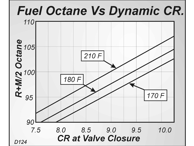
fuel octane, air coolant and oil temps, spark advance and plug heat range all effect the results, when you see a chart like these below, they provide a good guide to keep you out of potential trouble, but each combos unique and has a different potential to cause detonation, simply slowing the ignition advance , and changing to a different plug heat range, is sometimes all thats required to run lets say a 8.8:1 dynamic compression in one combo, but a similar one may only tollerat a 8.4 dynamic compression with the same mods
engbal5.gif

cpr2.jpg

heatvscpr.jpg

001-32.jpg

just be sure you verify all clearances
(piston to valve,
rocker to rocker stud,
rocker to retainers, etc. )
I think you made a good choice from what I see posted so far
Id install it strait up, IE no advance split overlap_


http://garage.grumpysperformance.com/index.php?threads/how-to-read-a-cam-spec-card.1477/


yeah lots of info/reading but it potentially prevents several issues


http://garage.grumpysperformance.co...ng-cam-and-shifting-the-lca.10553/#post-44949

http://garage.grumpysperformance.com/index.php?threads/cam-degreeing.9010/#post-35474

http://garage.grumpysperformance.com/index.php?threads/precision-measuring-tools.1390/#post-12997

http://garage.grumpysperformance.co...hanics-of-adv-ret-a-camshaft.4532/#post-12050

http://garage.grumpysperformance.com/index.php?threads/degreeing-in-a-cam-correctly.3097/#post-8240

http://garage.grumpysperformance.com/index.php?threads/cam-degree-equipment-tools.1759/#post-4440

http://garage.grumpysperformance.co...rect-custom-length-pushrods.14241/#post-72355
 

Attachments

  • Crower_HF_00227_522_549.JPG
    Crower_HF_00227_522_549.JPG
    87 KB · Views: 206
  • Crower_HF_00234_522_549.JPG
    Crower_HF_00234_522_549.JPG
    86.5 KB · Views: 205
Last edited by a moderator:
Note: to self ... ;) Grump talks alot about Cam LSA

LOBE SEPARATION ANGLE (LSA)
A camshaft consists of intake and exhaust lobes, and a key consideration when designing a cam is the lobe separation angle, sometimes also called the lobe displacement angle, or lobe spread.

The definition here is simply the distance in degrees, as measured on the cam, between the point of peak lift on the intake lobe and the peak lift on the exhaust lobe.

http://www.popularhotrodding.com/engine ... angle.html

http://www.compcams.com/Technical/FAQ/LSAproperties.asp


Tuck\o/

:!: EDITED:!! OR look at the BTW in Grumps previous Post... DOHHH :?
 
Last edited by a moderator:
most guys use the terms almost interchangably WHICH THEY ARE NOT in all cases!

LCA =(LOBE CENTER ANGLES)remember lobe center angles can be changed thru indexing the cam when degreeing it in, LSA (LOBE SEPERATION ANGLE) is ground into the cam during its manufacturing process.

Ill make this fairly simple, yes theres other factors like displacement and compression and the total durration and the intake design, you use at play here, but given equal lift and duratiion,
if you want a decent idle and especially if youve got EFI where the sensors are a factor the wider 110-116 LSA is going to generally be the better choice, if youve got a manual transmission or a higher than stock stall speed converter and some steep rear gears in the 3.73-4.88 range you might want to look into the tigher 105-108 LSA as it generally provides a tiny bit more torque and similar, or slightly better hp, at the cost of a rougher idle and a narrower power band


heres free cam selection software to narrow your choices

http://www.compcams.com/Pages/409/camquest-6.aspx

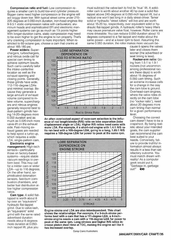
AS your displacement per cylinder increases the effective valve size per cubic inch decreases so you need a slightly tighter LSA and these charts should help.

LSAChart01.jpg


Longer rod ratios have a longer dwell at TDC ,
In theory thats more high rpm tq for the 6" rods due to more efficient use of cylinder pressure at those high rpms but cam timing, scavenging and compression ratio must match to get the benefits, and detonation could be slightly more common
MATCHED ,CAM TIMING, PORT CROSS SECTION AND LENGTH< <COMPRESSION< AND EXHAUST HEADER CONSTRUCTION, DESIGNED TO MATCH THE LONGER ROD DWELL TIME IS REQUIRED TO ACCESS THE POTENTIAL BENEFITS, FAIL TO DO THAT CORRECTLY AND YOU LOOSE THE SLIGHT POTENTIAL GAINS
Duration_v_RPM-Range_wIntakeManifold01.jpg

CamUsageChart01.jpg


you should also keep in mind that a roller cam valve train with the same lift and duration can provide a good deal more port flow and resulting power.
dcr.jpg

flatvsroller.jpg

FlatVsRollerChart.gif

ramprate.jpg


pistonposition1.jpg

pistonposition2.jpg

lcazx.png

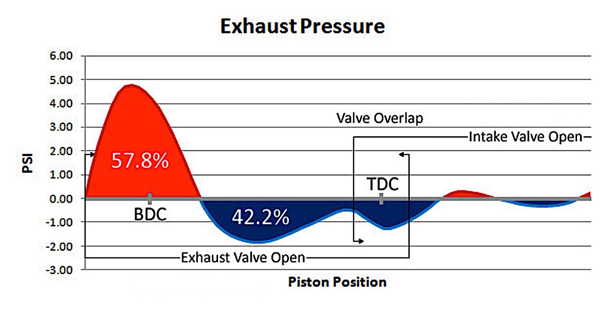
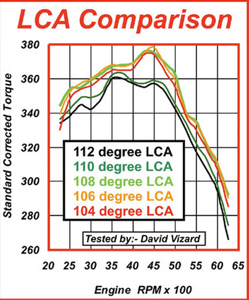
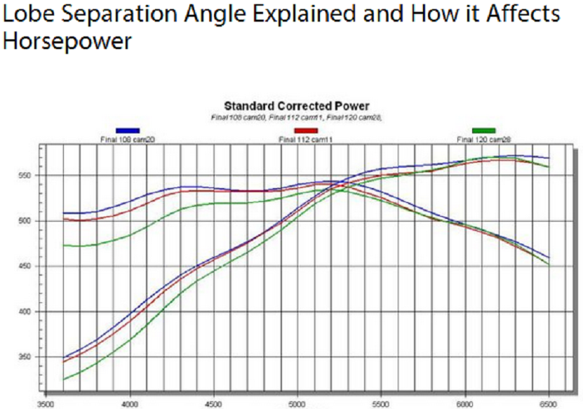
as a general trend tighter LCA cams tend to allow the engine to breath better and scavenge the cylinders more effectively, during the over lap period , notice the tighter BLUE line, in the chart posted above, 108 degree cam compared to two other cams with the exact same lift and duration but on a wider LCA
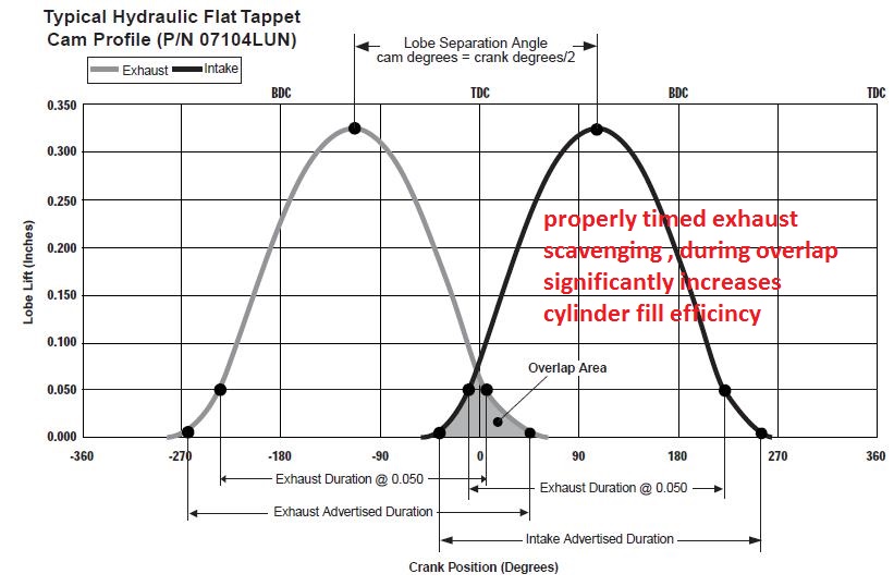
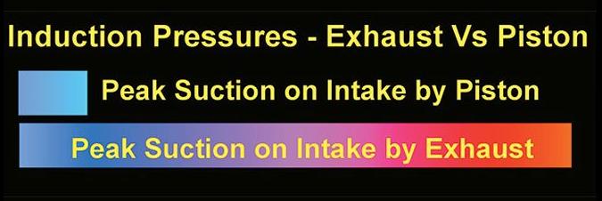
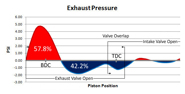
pressure charts on most engines will show intake pressure changes per deg of rotation in an engine spinning at a above about 3600 RPM. With the right exhaust,header design will effectively "pull" on the intake port generated by the exhaust inertia leaving thru the headers primary tubes during the overlap phase can be many times stronger than the "pull" generated by the piston moving down the bore. This does a LOT to help efficiently increase the fill rates of the cylinder and build cylinder pressure, as it increased the mass of trapped fuel air mix as the valves seat..

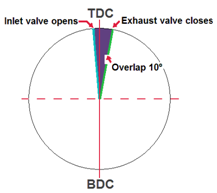
In the above,diagram, you are looking at overlap @ 0.050". You really need to look at the whole overlap triangle. few cams will have negative overlap at seat duration (in any modern V8), but many of mild street cams have little or no effective overlap" @ 0.050".
pistonposition3.jpg

pistonposition4.jpg


on average Ive found advancing or retarding a cam a full 4 degrees moves the whole torque curve about 150rpm on most of the engines I build.

now horsepower , is calculated as torque times rpm, divided by 5252
so lets say an engine makes 400 ft lbs of torque at 3800rpm and 370 ft lbs at 5500rpm
thats 387 hp
retard the cam 4 degrees
you potentially could get 398 hp or a gain of 11 hp but you also tend to loose about the same on the lower end of the power band, and because the lower end is almost always used far more than peak power its rarely a huge benefit, thats one reason why most cam manufacturers tend to have cams degree in 4 degrees advance on a dot-to-dot instal.
keep in mind port cross sectional area restricts flow rats as rpms increase, so your frequently not going to get the full potential benefits

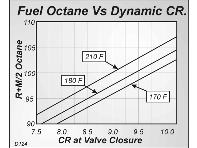
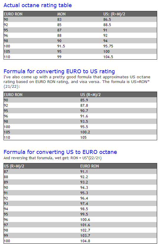
octanedf.png

http://garage.grumpysperformance.co...ectly-and-get-it-to-last-cam-install-info.90/

http://garage.grumpysperformance.com/index.php?threads/calculating-overlap-and-lsa-or-lca-etc.480/

http://garage.grumpysperformance.com/index.php?threads/cam-gear-and-timing-marks-etc.724/#post-1021


First Id point out that nearly everyone occasionally confuses or at least makes the mistake of using the wrong abbreviation, (LSA, and LCA) these are terms,that are almost, at least in many discussions interchangeable. which they are not.
LSA =LOBE SEPARATION ANGLE ........LSA is ground into the cam during manufactured, and can,t change,

http://garage.grumpysperformance.co...lsa-effects-your-compression-torque-dcr.1070/

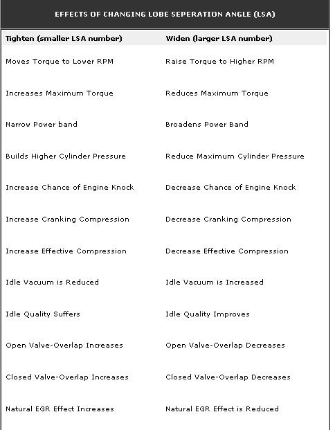
LOBE SEPARATION ANGLE
Above 114 Deg. = Extremely Wide
114-112 Deg. = Wide
112-110 Deg. = Moderately Wide
110-108 Deg. = Moderate
108-106 Deg. = Moderately Tight
106-104 Deg. = Tight
Below 104 Deg. = Extremely Tight

VARYING LOBE SEPARATION ANGLE
Tighten.................................................Widen
Moves Torque to Lower RPM.................Raise Torque to Higher RPM
Increases Maximum Torque..................Reduces Maximum Torque
Narrow Power Band..............................Broadens Power Band
Builds Higher Cylinder Pressure............Reduce Maximum Cylinder Pressure
Increase Chance of Engine Knock.........Decrease Chance of Engine Knock.
Increase Cranking Compression...........Decrease Cranking Compression
Increase Effective Compression............Decrease Effective Compression
Idle Vacuum is Reduced........................Idle Vacuum is Increased
Idle Quality Suffers...............................Idle Quality Improves
Open Valve-Overlap Increases.............Open Valve-Overlap Decreases
Closed Valve-Overlap Increases...........Closed Valve-Overlap Decreases
Natural EGR Effect Increases................Natural EGR Effect is Reduced
Decreases Piston-to-Valve Clearance...Increases Piston-to-Valve Clearance
[color:red]LCA =(LOBE CENTER ANGLES)remember lobe center angles can be changed thru indexing the cam when degreeing it in[/color]
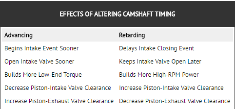
ADVANCING / RETARDING CAM TIMING

KEEP IN MIND MANY CAMS ARE FACTORY SET UP TO BE 4 DEGREES ADVANCED if INSTALLED DOT-TO-DOT

ADVANCING.
Begins Intake Event Sooner........................
Open Intake Valve Sooner..........................
Builds More Low-End Torque.......................
Decrease Piston-Intake Valve Clearance....
Increase Piston-Exhaust Valve Clearance...

RETARDING
Delays Intake Event Closes Intake
Keeps Intake Valve Open Later
Builds More High-End Power
Increase Piston-Intake Valve Clearance
Decrease Piston-Exhaust Valve Clearance

keep in mind theres three basic factors that are interlinked in that each has some effect on how the other two will effect the engines power curve

duration controls the number of degrees of rotation the valve takes from the time it lifts off its seat until it re-seats, the is the TIME the valve will be open and effects the rpm range , the cam will most efficiently operate in.
LIFT, controls the distance the valve opens,and combined with the valve diameter limits the valve curtain, so combined with duration in controls potential flow.
your engine displacement, compression ratrio, potential head flow and header scavengine also will effect the power curve\
fe008cfd.gif

porting+valve_area.jpg

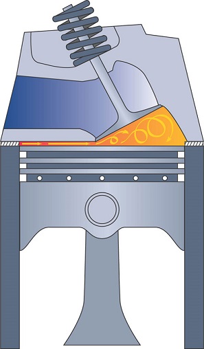
LOBE SEPARATION ANGLE will effect how effectively the exhaust can scavenge the cylinders and low rpm reversion pulse strength to some degree thus idle quality, as the period of time while both valves are open at the same time, greatly increases cylinder scavenging.
EXFLOWZ4.jpg

116_0403_basic_10_z.jpg

ignitiontiming.png

engbalq5.gif

cylinderpresgr.png

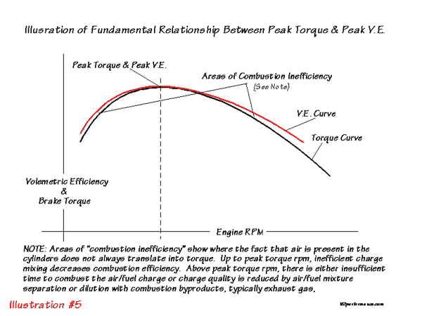
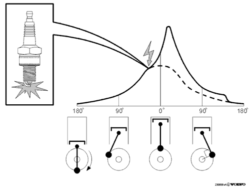
at lower engine rpms less ignition advance is needed because theres more time available, between ignition and cylinder pressure building , over the piston ,as the flame crosses the cylinder, so most of the pressure occurs after the cranks rod journal passes TDC, at lower rpms this burn & pressure build can take 50 thousands of a second, as rpms increase the time available is much shorter requiring a longer lead time or a greater "ADVANCE" but as rpms further increase ,turbulence caused by rapid compression increasingly speeds burn times
exhaustpressure.jpg

Cylinder-Pressure-lLrg.gif


LSAChart01.jpg


if you really want to confirm you were having to fight dinosaurs on your way to school when you were a kid
like your grandkids are 100% convinced was a FACT!
you get your old calculator out of the drawer and confuse the hell out of them

versa2.jpg

http://garage.grumpysperformance.co...-descriptions-dont-tell-you.12357/#post-61139
 
Last edited by a moderator:
"
A buddy told me to get a 3/4 cam. Ive heard people use that description before, but what the heck is does it mean?

example

http://www.speedwaymotors.com/1949-53-F ... M,422.html


http://www.jegs.com/i/Crane/270/100172/10002/-1#
"

MANY ......MANY years ago cams were commonly advertised that way for the flat head fords, 406 fords, 292 fords,tri-power olds, nail head buicks,348-409 chevys etc, were sold as 1/2 race or 3/4 race or FULL RACE cams, in catalogs from places like JC whitney, mostly because there was fewer custom cam suppliers, and most customers knew far less than they do now, and many cams were based on regrinds on stock cam cores that provided a bit more lift or duration but maintained at least some of the O.E.M. cam characteristics.
back in the 1940-late 1960s,cams like the original sbc z28 cam were considered "3/4 race" and the "off road z28 cams were FULL RACE"


basically its a nearly meaningless marketing term from the 40s-late 60s, from mail order cam suppliers advertising in magazines, or companies like jc Whitney, a full race cam in those days generally was designed to take advantage of the max lift and duration the stock valve train could be made to work with,and still maintain some durability.

1/2 race generally burbled at idle and had some improved hp, generally in the 210-220 dur range on a wide 112-116 lsa

3/4 race loped at idle and was generally in the 220-230 duration range on a tighter 110-112 lsa

full race loped at idle, had good hp and generally fell in the 235-255 duration range om a 106-110 lsa

the people selling cams, as 1/2 or 3/4 race cams, figured if you needed more info than that you were supposed to know enough to work with a cam company, on your combos needs

today you fill out a question sheet or use software to select the correct cam.


this might keep you from making a HUGE mistake, it gets you into the correct ball park on dur. and lift most of the time, once you know that info you can use the info to select any brand cam

http://www.compcams.com/CAMQUEST/

engbal5.gif


fe008cfd.gif


116_0403_basic_08_z.jpg


http://www.compcams.com/Technical/TimingTutorial/
800-615-ValveTimingIllustration-002.gif

116_0403_basic_10_z.jpg


example, lets assume your looking a a race cam with a listed 260 duration
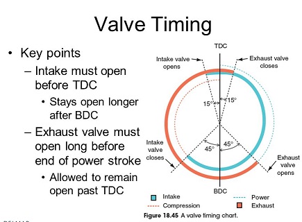
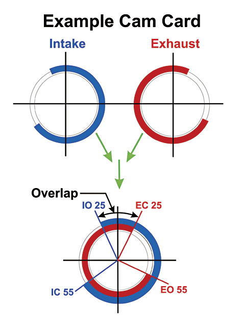
What is a valve timing diagram? Simply put, the numbers on the cam card will look like INTAKE OPENS at 20 degrees BTDC (Before Top Dead Center) and CLOSES at 60 degrees ABDC (After Bottom Dead Center), EXHAUST OPENS at 60 degrees BBDC (Before Bottom Dead Center) and CLOSES at 20 degrees ATDC (After Top Dead Center).

this timing may also be written as:
20 - 60
60 - 20
Of course, most of the time these four data points are rarely ACCOMPANIED WITH THE EXACT CAM LIFT THAT THESE NUMBERS WERE TAKEN AT!

Many times the timing diagram fails to specify the total duration of the timing diagram. Let's calculate the total duration of the intake by simply adding together 20 plus 60 and adding the constant 180 which totals 260. The exhaust will calculate as 60+20+180=260. Let's assume these numbers were taken at .050 inches of cam lift.
Now the timing may be written as:
20 - 60 = 260.0 @ .050" cam lift
60 - 20 = 260.0 @ .050" cam lift

Now let's play GAMES WITH THIS TIMING DIAGRAM. If we ADVANCE THE CAM 5 crankshaft degrees the SAME timing diagram becomes:

25 - 55 = 260.0 @ .050" cam lift
65 - 15 = 260.0 @ .050" cam lift

Notice that the left side numbers INCREASE by FIVE and the right side numbers DECREASE by FIVE.

If we RETARD THE CAM 5 crankshaft degrees from the ORIGINAL timing diagram it becomes:

15 - 65 = 260.0 @ .050" cam lift
55 - 25 = 260.0 @ .050" cam lift

Notice that the left side numbers DECREASE by FIVE and the right side numbers INCREASE by FIVE.

Remember, all three of these timing diagrams are from the SAME CAMSHAFT! Only the ADVANCE AND RETARD of the camshaft IN REFERENCE to the CRANKSHAFT has been changed!

http://garage.grumpysperformance.com/index.php?threads/port-speeds-and-area.333/

http://garage.grumpysperformance.com/index.php?threads/valve-seat-angles-and-air-flow.8460/

http://garage.grumpysperformance.com/index.php?threads/more-port-flow-related-info.322/

port2.jpg

port3.jpg

port1.jpg


USE THE CALCULATORS to match port size to intended rpm levels... but keep in mind valve lift and port flow limitations[/color]
http://www.wallaceracing.com/runnertorquecalc.php
http://www.wallaceracing.com/ca-calc.php
http://www.wallaceracing.com/area-under-curve.php
http://www.wallaceracing.com/chokepoint.php
http://www.wallaceracing.com/header_length.php

http://www.pontiacracing.net/js_header_length1.htm


I think this chart above is frequently either ignored or mis-understood
0607phr_11_z+camshaft_basics+lobe_centerline_angle_determination_chart.jpg


camcomp.jpg

porting+valve_area.jpg


AFR_Torque.gif

Stoichd.gif

volumetric.gif
 
Last edited by a moderator:
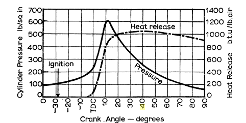
one of the most common mistakes I see is the one most of us make early in our hobby, its the one where we select a cam thats designed for max hp at maximum rpms, because of some magazine article or something a buddy suggests.
the second most common mistake is probably either not verifying the valve train geometry and all other engine clearances are correct or failing to degree in the cam, or at least verify it close to correctly installed and then being amazed when parts fail or the engine runs badly
now most of us go down that road, and some of us never admit that the crappy driving characteristics and loss of low rpm torque are really not worth it in a street driven car,
yes you'll have that lopey idle, and possibly, if your lucky a decent peak hp/tq curve, once the engines running up in the rpm band where the cams designed to operate,
but in most cases a milder cam duration would produce more AVERAGE USABLE HORSEPOWER and the car would be faster.
remember the old muscle cars needed those long duration cams to allow the 40-50 year tech,old crappy flowing heads too breathe, but with the better aftermarket and in some cases factory heads available today, a little less duration is required to build better hp.
it was unheard of to get the flow numbers we have available today.
even the crappy vortec truck heads vastly out flow most of the FUELIE CORVETTE HEADS most guys heard about when they were younger.
you might want to read thru this link carefully
http://victorylibrary.com/mopar/cam-tech-c.htm

http://community.fortunecity.ws/silverstone/pontiac/101/tech/cams.htm
 
Last edited by a moderator:
http://www.compcams.com/Technical/FAQ/LSAproperties.asp

http://www.empirenet.com/pkelley2/DynamicCR.html


Effects Of Changes In Cam Timing And Lobe Separation Angle
A CORRECTLY TUNED SET OF HEADERS , MATCHED TO A CORRECTLY DESIGNED CAM TIMING HAS A SIGNIFICANT EFFECT ON INTAKE FLOW AND CYLINDER SCAVENGING EFFICIENCY, EXHAUST SCAVENGING CAN BE 5 TIMES STRONGER THAN THE PISTON, MOVEMENT INDUCED NEGATIVE PRESSURE (VACUUM) IN THE INTAKE RUNNERS
EXFLOWZ5.jpg

volumetric.gif

exhaustpressure.jpg

EXFLOWZ4.jpg


The following tables illustrate how variations in lobe separation angle and cam
timing will effect the behavior of the engine in which the camshaft is installed.

EFFECTS OF ALTERING CAMSHAFT TIMING
Advancing.......................................... Retarding
Begins Intake Event Sooner................. Delays Intake Closing Event
Open Intake Valve Sooner ........................Keeps Intake Valve Open Later
Builds More Low-End Torque................. Builds More High-RPM Power
Decrease Piston-Intake Valve Clearance Increase Piston-Intake Valve Clearance
Increase Piston-Exhaust Valve Clearance Decrease Piston-Exhaust Valve Clearance


http://www.enginebuildermag.com/Article ... teria.aspx

http://www.circletrack.com/techarticles ... index.html


LSAChart01.jpg


in case you don,t understand the chart, you take the engine displacement PER CYLINDER divided by the valve diam. then you use that on the chart to locate the lsa
example
lets assume youve got a 383sbc, 383/8=47.88
divide that by intake diam., lets say 2.02 and you get 23.7 youll see the ideal is near 105 lsa, but then you ask,WHY are most cams ground with a 110-112 LSA its because that tight lsa may maximize the peak volumetric efficiency,and peak hp/torque, it will also be far from ideal at low speed, with a lopey idle, or for emission testing or for ease of low and mid rpm ease of tuning or for sensors to read because of low rpm reversion in the intake runners.so a compromise with a wider LSA is used, sacrificing a bit of peak hp for better average drive ability and lower emissions and better mileage

look at the chart,
ctrp_0212_05_z+performance_camshaft_tuning+lobe_seperation_graph.jpg
 
Last edited by a moderator:
Assuming a constant lobe center angle

Longer duration
more peak power, rougher idle,
higher fuel consumption,
higher emissions,
less torque at low RPMs,
power peak occurs at higher RPM,
power rpm band widens and moves up

Shorter duration
the opposite of the above results


Assuming constant duration

Tighter lobe centers
more peak power,
higher fuel consumption
rougher idle
more torque at low RPMS,
peak power occurs at LOWER RPM,
higher emissions,
power RPM band gets narrower and moves DOWN

Wider lobe centers
opposite of above


Assuming constant lobe centers and cam duration


Advancing the cam
slightly improved low rpm torque,
slightly reduced peak power
imperceptible change in emissions, idle & fuel consumption

Retarding the cam
opposite of the above
 
Last edited:
using .050 lift to compare overlaps about as valid as selecting a girl freind based on the color of hair brush in her purse
116_0403_basic_10_z.jpg


overlap is very important and its measured from valve seat to valve seat, so ALL the flows a factor


http://www.epi-eng.com/piston_engine_te ... basics.htm

http://www.iskycams.com/degreeing.html

http://www.superchevy.com/technical/eng ... index.html

0505phr_exh_02_z.jpg


http://www.superchevy.com/technical/eng ... index.html

http://www.stockcarracing.com/techartic ... index.html

each combo of displacement,intended rpm power band, compression ratio,head flow rates,induction, port cross section, etc will have a limited range of nearly ideal cam timing
there are calculations that can be used to get you right in the ideal ball park


http://www.wallaceracing.com/chokepoint.php

http://www.wallaceracing.com/chokepoint-rpm.php

http://www.wallaceracing.com/dynamic-cr.php

http://www.kb-silvolite.com/calc.php?action=comp2

http://www.wallaceracing.com/lpv.php

http://www.wallaceracing.com/dynamic-cr.php

http://www.compcams.com/Camquest/default.asp

http://www.auto-ware.com/software/eap/eap.htm
 
Last edited by a moderator:
"GRUMPYVETTE??
Help me understand this a little better--why do some supercharger cams have a lsa of 114 degrees? I had always assumed that it was to prevent bleeding off boost. Is this correct?"


your correct,.... but your partly comparing apples to oranges, between the n/a and supercharged combos

on a naturally aspirated engine your looking for the the pressure drop in the cylinder caused by the piston moving rapidly away from TDC to allow the higher outside atmospheric pressure and the inertia of the last exhaust charge exiting thru the headers to push and drag the next fuel air charge into the cylinder, so having some extra overlap in valve timing tends to help

0505phr_exh_02_z.jpg

cambasics.jpg


READ THESE LINKS
http://ezinearticles.com/?Supercharger- ... id=2473412

http://www.chevyhiperformance.com/tech/ ... index.html

http://www.superchevy.com/technical/eng ... index.html


on a supercharged engine your intake pressure is far higher and lasts much longer in the intake port so the exhaust valve closing a bit earlier tends to trap and hold that intake charge while the intake is still flowing, and filling the cylinder, provided the overlap does not allow that pressurized intake charge to blow out the exhaust, but because the total volume of the burnt gases are higher the exhaust duration tends to be increased, in a supercharged engine vs a n/a the overlap in valve timing needs to be reduced, so the exhaust valve needs to open longer but the overlap needs to be reduced so a wider LSA is used.
 
Supercharging Basics

Many people have the impression that a supercharger is an exotic performance part found on wild street machines or racecars. There's also the impression a supercharged vehicle is difficult to drive on an everyday basis. Nothing could be further from the truth on both counts

First, a supercharger is nothing more than a large air pump that can provide greater than atmospheric pressure (boost) to an engine. When was the last time you thought of an air pump as exotic?

Second, when building an engine for supercharging (other than a racing application), it's generally built for low to mid-range torque and power just as a stock engine would be. Because an engine may be left stock when utilizing a supercharger, your vehicle would be no more difficult to operate or maintain. As you can see, a supercharger isn't really exotic. It's really quite practical.

The guidelines below have been established to assist in building a basic street supercharged engine. Engine durability and dependability are two factors given strong consideration in these guidelines as current supercharger kits are developed for everyday use. However, superchargers are quite capable of reliable use in competition.

Engine Preparation

The extent of the engine preparation will depend entirely on how the engine is to be used. A supercharger can be installed on a stock engine with cast pistons and a cast crank as long as moderate boost (below 8 lbs.) is maintained and any detonation is strictly controlled. Engine speed should also be limited to 5,000 rpm. Detonation on cast pistons can easily break ring lands. Too much boost and/or detonation on a stock or worn engine can cause piston damage or burned valves.

Most late model "smog" engines work well with a supercharger due to their lower compression ratios and smaller cam profiles.

Supercharged Engine Guideline

1) 7.0:1 to 9.0:1 compression ratio: The optimum compression ratio is 8.0:1.

2) 4-7 psi boost level: This range of boost has proven to be the best compromise for power and reliability.

3) Engine rpm: When using stock cast pistons, the engine should be limited to a maximum of 4,500-5,000 rpm. Exceeding this limit may over-stress the cast pistons causing failure. Blueprinting an engine using the proper components will allow higher rpm reliability and will maximize a supercharged engine's potential.

4) Detonation (pinging): Detonation is the single most destructive force in a supercharged engine and steps must be taken to eliminate it. This may include lowering boost level, retarding timing, installing a boost timing master, increasing fuel flow to prevent leanout, and/or using a fuel additive to raise octane level. The cooling system also needs to be in good condition to prevent overheating, which may lead to detonation.

If an engine is to be driven hard or under load, as in towing, a thorough blueprinting should be considered. Forged pistons, with their inherent strength and ability to withstand higher temperatures, are recommended. Follow the piston manufacturer's recommendations for piston-to-cylinder clearances.

A compression ratio exceeding 8.0:1 is not recommended, nor is it necessary for brisk performance from a supercharged engine. If raised to this level, fuel, ignition timing, and total boost become critical factors.

Next consideration would be the piston rings. They should always be the best quality available because the piston rings take as much abuse as any other component in an engine. "Moly" or "Double Moly" piston rings (iron piston rings coated with Molybdenum Disulfide) are an excellent choice for supercharged street engines. They seat quickly and wear well. For hot street or competition, where higher boost will be used, chrome or stainless steel piston rings should be considered.

Consideration should be given to using heavy-duty fasteners especially on the connecting rods and main caps for added durability and strength. If the engine will be run with a high boost level (12 psi or more), high-performance head gaskets with built in stainless steel O-rings are recommended because they can withstand the higher combustion pressure and temperatures encountered in a supercharged engine.

Cylinder Head and Valvetrain Preparation

Weak valve springs or burned valves can lead to backfires. When an engine has more than 50,000 miles on it, inspect the entire valvetrain. If the valve springs require replacement, factory heavy-duty springs should be used. With the use of an aftermarket camshaft, follow the camshaft manufacturer's recommendations for valve springs.

For proper cooling of the valves, use a three-angle, "street-type" valve grind. With the additional combustion temperatures normally generated in a supercharged engine, the wider valve seats will provide better cooling of the valves, and the three-angle valve grind will provide better sealing of the valves

When any port work is being done, most of the effort should be directed to the exhaust ports. The supercharger will overcome most minor restrictions on the intake side of the cylinder head.

The use of O-ring head gaskets requires receiver grooves in the heads and block milled by a competent machine shop.

Camshaft Selection

A supercharger can overcome inadequacies in a stock cam up to about 4,500-5,000 rpm. You will typically find that performance with a blower will not be significantly enhanced below these speeds with a cam change. However for optimum performance at higher rpms, a more aggressive cam will provide substantial power increases.

For best performance with a blower you should look for a cam that has higher lift and longer duration on the exhaust side. Street performance with a blown engine is usually best with a cam that is ground with a 112 to 114 degree lobe separation. Blower cams can be typically run "straight up." Note that a blower has tendency to lessen the rough idle of radical cams.


Other Preparation

Air Cleaners: Good quality air cleaners should always be used on a street supercharger. Allowing dirt or debris to go through the supercharger may score or gouge the rotors or case.

Exhaust System: The less restriction the better. Use large tube headers with low restriction type mufflers. Low speed torque will not suffer by using larger primary tube headers as is typical on unblown engines.

Carburetion: At full throttle a blown engine can require 50 percent more air than an unblown engine and as a result needs a larger carburetor(s) in order to make maximum power and boost. If your blown engine is primarily driven on the street at moderate engine speeds (under 4,000 rpm) you won't need a larger carburetor(s).

Typically the carburetors(s) will need to be enriched by 5 to 10 percent on the primaries and 10 to 20 percent on the secondaries. The idle mixture screws may need to be enriched by one or two turns. In either case, the carburetors need to be jetted properly to prevent a lean condition. A lean condition can lead to overheating and detonation.

For initial start-up, it's better to have a slightly rich condition to help prevent the engine from overheating. After initial start-up, check the spark plugs for proper reading (color) and adjust the carburetor(s) accordingly. You want to see a medium to dark tan color.

Ignition System: Set the initial timing at 6 to 10 degrees BTDC. The distributor advance curve should be calibrated to give a total advance of 28 to 34 degrees by 2,500 rpm. Most late model OEM electronic ignition systems have the capability of working well with a supercharger. Some distributors with computer controlled advance curve and timing may not be compatible with a supercharger because of the preset timing and sensors they require. Any of the aftermarket high performance standard or electronic distributors should function well when properly calibrated. A quality electronic unit would be the preferred choice for best all around performance and reliability. If detonation is encountered, a boost/retard system that works with manifold vacuum and pressure is recommended.

Supercharger Drive Ratios

The reason we cannot provide an exact boost figure is that camshaft profiles, cylinder head configuration, and carburetor size can all have effect on the amount of boost that will be shown on the boost gauge. To illustrate, if you have small port heads and a stock cam, at higher engine rpms the blower will be unable to overcome these restrictions and boost will build up in the manifold producing an artificially high boost reading. Conversely, changing the cam and heads will make the boost reading go down but the power will increase at higher engine speeds.

Boost is a direct result of three factors: engine size, blower size, and the speed the blower is driven in relationship to the engine speed. Bigger blowers driven at the same speed as a smaller blower will produce more boost.

Normally decreasing the upper pulley by one tooth or increasing the bottom pulley by one tooth will raise the boost one or two pounds. Conversely increasing the tooth count on the upper pulley or decreasing the teeth on the lower pulley by one tooth will lower the boost by one or two pounds.

If you desire a substantial change of boost you can just interchange the top pulley for the lower pulley and change the blower from underdrive to overdrive. However, swapping pulleys will approximately double the amount of boost you will get. This should only be done for extreme high-performance race engines by those with substantial supercharger experience.

Thanks to Holley Performance Products, Inc. for contributing to this guide.
 
HERES TWO RELATED POSTS FROM THE ISKY CAMS WEB SITE, and a couple good related links


Longer Exhaust Duration: Is this really necessary?

Most stock camshafts from American production V8, V6 and 4 cylinder engines manufactured today are ground with the longer exhaust lobe duration. Or, another way of looking at this is that they are ground with shorter intake durations! The former embraces the viewpoint that either the Exhaust Ports or Exhaust Pipe system is somewhat restrictive, and is in need of an assist. The latter suggests that the intake system is rather efficient and cam timing can be trimmed back a bit with out much sacrifice in power, in order to maximize throttle response and cruising efficiency.

Take your pick here. There is no absolutely correct viewpoint - because both are probably true! In a stock engine running at conservative RPM levels, for the sake of overall efficiency, fuel economy and a quiet smooth running engine, this staggering of intake and exhaust duration is quite common and appropriate.

However, High Performance is another thing entirely. Change one factor, let's say in this case, the exhaust system (installing headers and larger pipes) and you have just negated in most cases, the need for that longer exhaust lobe. Now couple this change with a different intake system and camshaft and you have really scrambled the equation. But, wait just a moment. Why is it that so many people (racers & cam grinders alike) insist on running a cam with longer exhaust duration regardless of what equipment is employed? The answer is "habit". Most of them have been somewhat successful in doing it their way and will probably never change unless virtually forced by circumstances to do so.

Before we go any further however let's review what it actually is we are trying to do with an engine when we attempt to make more power. Our best result comes when we are cognizant of the fact that an engine is basically an air pump. We pump it in and out (although in a different form) and we have problems when one side or the other is restricted. Balance or the equilibrium or flow should be our objective, unless of course we are not trying to make more horsepower!

Example #1 (Oval track racing) Here, I have often observed that the most experienced drivers are those who are most likely to run a single pattern (equal on intake and exhaust duration) cam. Why? Because such cams always, I repeat always make more torque! These veterans have a more educated foot and greater experience in feathering the throttle in the corners. They can therefore, utilize the benefit of added torque, in the lower to mid RPM range, to their advantage.

Their counterparts, the younger drivers on the circuit, generally are not as experienced and may at times actually get "crossed up" in the corners especially with a lighter car or when they are learning the ropes. In their case, a longer exhaust duration is often the more appropriate choice. It will often help them to drive better, more "flat footed" if you will, without consequence. But please for the sake of accuracy, let us be truthful. The benefit comes from an actual bleeding off of low to mid range torque, which is always what happens when Exh. Duration is lengthened, not from any improvement. The improvement, (if any) would come because of an improvement in scavenging at the extreme upper end of the power curve and would usually be marginal at best. Yet the so-called "extra power" potential of a longer Exh. Duration cam is most often why they are touted - power most people are backing away from at the end of the strait away!

Example #2 (Drag Racing) At the drag strip it's a little different and I feel more honest. Here, racers have long enjoyed longer exhaust and longer durations across the board (If I may add specifically for the purpose of "killing" low-end torque) to keep the tires from too easily breaking lose. This has been successful and sometimes actually results in a slight increase in top end power - something you can actually use in drag racing since it is a full throttle endeavor through the lights. Keep in mind here though, it's quite possible that a longer duration cam overall would have done just as well or better. In other words if you needed that longer exhaust for top end, perhaps the intake could have benefited from such a lengthening as well.

One of my favorite expressions is how "The Drag Racing mentality has infiltrated the ranks of Oval Track". Many have crossed over and made the switch in the past 10-15 years and some have brought their preconceived notions about how to cam an engine with them. A few may actually read these concepts and if they do so will at least come away with a better understanding of what they are doing. On the other hand they also could find that this information might actually help their cars to run just a bit faster!

intake Restriction and Over Scavenging: "Waste not...Want not!"

It is certainly an over simplification to make the statement "that which is not wasted, should be inducted". However, in the case of restricted intake systems and in particular 2-BBL carb rules, it is not far off the mark. Engines with such restrictions are "choked off" to the point where they will not run much past 6500 RPM (if even that high) without dropping off sharply in power. You might have trouble running very fast yourself if someone had your windpipe choked down to say 50 or 60% of it's normal capacity. Under such conditions, would you volunteer to give blood at the Red Cross? Of course not, but without knowing so, racers often do the equivalent with their engines by running a camshaft better suited for a 4-BBL class! How So?

If you'll recall in last months tech tip: "Longer Exhaust Duration: Is This Really Necessary?" I discussed how, through habit, many racers and cam grinders alike are predisposed to running camshafts with longer exhaust durations, whether they need to or not! Well, in the case of restricted intake applications, if there was ever a situation in which you'd want to avoid the longer exhaust "trap" it's here! Especially the 8, 10, 12 or even longer degree spreads, I often discover people employing.

Use such a cam at you own risk - and don't be surprised to find that your exhaust temperatures are unusually high. Your headers in fact may even glow cherry red. There is a very good reason for this. Raw (unburned) fuel is burning "late" or in the pipe (header/manifold). You may have a good equilibrium of flow going here but there is just one problem. Much of what should be inducted into the cylinder is being scavenged out the exhaust! You see, although back pressure in an exhaust system can be restrictive, the only thing that could be even worse is a reduction of it to the point where you are now, in effect pulling a vacuum. In the case of an intake restriction, very slight back pressure is preferable to avoid "over scavenging".

Yes, Yes I know. You are probably thinking "what's wrong with a little scavenging?". Well, nothing if you can afford it. But with intake restrictions (either small 2-BBL carbs and/or restrictor plates) you must be very careful. You already have reduced intake potential and therefore simply cannot be cavalier about valve overlap and scavenging or you'll be way down on power and have those nice bright cherry red pipes to show for it! Case in Point: One racer who called me was in this exact situation and was running, not surprisingly, a 14 Degree longer exhaust duration. It was Friday afternoon and he needed a cam the next day for the last "points race" of the season and UPS had already picked up at Isky. "Too Bad" I said, "You don't have a set of those low ratio break-in rocker arms because they could really help in this case". " I do have some" he said "but they are only 1.2:1 ratio - is that okay?" I told him to use them (on his exhaust valves only of course) and he finished the race 2nd having come from the back of the pack. Later we made him the right cam so he could avoid this make shift approach.

Unfortunately, the symptoms are not always as obvious as in this case to allow for a speedy diagnosis. Also, it's not only longer exhaust duration that causes the problem. Although it is usually the primary offender, it is often coupled with too close a lobe separation angle of say 104 Degrees. A widening to 106 Degrees or preferably 108 Degrees (some go even wider) is usually prudent.

I am not absolutely dead set against a slightly longer exhaust duration in these cases as a 2-4 Degree longer exhaust lobe is permissible under some circumstances (if your running a completely stock exhaust system including mufflers for example). Each case is different, depending upon the equipment employed. I might even recommend shorter exhaust duration to some; if I feel they have "overdone" their exhaust ports and or exhaust system a bit. What matters is the end result and if you're out of balance on one side simply employ what I call the "Great Law of Compensation" to bring you back to that equilibrium of flow.

So, how can you tell if you may need to make some of these changes in your camshaft? Well, short of trying a lower exhaust rocker arm ratio, you can increase exhaust valve lash .004" - .008" temporarily to see if there is any improvement. You can also try and increase restriction (smaller headers or pipes, or in the case of open headers a longer collector) and simply observe the results. Remember, "One test is worth a thousand expert opinions". Keep this old axiom in your "tool box" and you'll be ahead of the game. How do you think Smokey's shop got to be "The best Damn Garage in Town" anyway? Yes, he had those country smarts, but his experiences in racing and his willingness to test are legendary!
 
Last edited by a moderator:
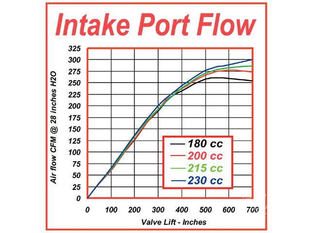
RB69SS396Conv posted this info, it may help some of you guys

"ICL and LSA are 2 VERY DIFFERENT things.

The event that the entire cam is "measured" off of, is ICL (Intake Center Line). This is the point of max lift of the intake valve, measured in degrees of crank rotation. It occurs about 90° of crank rotation ATDC on the intake stroke; that is, when the piston is about halfway down. In practice it's actually a little later than that usually, between 100° and 110° ATDC.

LSA is something COMPLETELY ELSE. It is not related IN ANY WAY WHATSOEVER to ICL. It is Lobe Separation Angle; it is the number of degrees of cam rotation from the center of the exh lobe to the center of the int lobe. Max opening of the exh valve is about when the piston is halfway up on the exh stroke; i.e. about 90° of crank rotation BTDC, as the piston is coming up. Most of the time it's just a little before that; again, at 100 to 110° or a little more.

Since 1 cam degree = 2 crank degrees (i.e. the crank rotates twice as fast as the cam), then if you add up the # of degrees BTDC the exh peak is and the # of degrees ATDC that the int peak is, you get a number somewhere around 200 - 220 crank degrees. There are HALF that many cam degrees between those 2 events; typically something in the range of around 110 degrees of cam rotation.

ICL can be changed by dinking around with the timing set. LSA is ground into the cam and cannot be changed after the cam is made. And, the cam grinder can control the LSA, but he CANNOT "control" the ICL. The installer does that. The grinder can grind the intake lobe at whatever point with respect to the dowel pin to make a "nominal" timing set align it to some point or other (which is what "grind in advance" and the like means), and can specify where he thinks his cam should be installed, but he cannot actually cause that to happen unless he physically goes to the builder's shop and sets up the ICL himself.

There is no "universal" "standard" for the "straight up" ICL. Every cam can be different. The "straight up" ICL for any given cam is whatever the grinder says it is. Since there is no "universal" "straight up", there is also no way to talk about "advance" or "retard", except if the cam grinder's spec for "straight up" is also known. It's entirely possible that, say, a 108° ICL might be "advanced" for one cam, but "retarded" for some other cam.

Since the "base" event for measuring the cam is the ICL, that means that if the cam is ground with a large LSA, it opens the exhaust relatively early compared to the int opening.

Any cam can be installed at any ICL. This doesn't change the LSA. "Advancing" or "retarding" the cam, either by the timing set or by grinding "advance" into it, doesn't change the LSA.

In general, if you take a cam and advance it (which moves both the ICL and the ECL together but does not change the LSA) you will move the peak torque and HP RPMs down a little bit but won't change the numbers themselves. Retarding does the reverse. Exactly how much, depends on ALOT of other factors; but the general rule works across the board.

In general, if you take a cam with a given ICL and LSA, and measure the engine's torque and HP vs RPM, and then put in an otherwise identical cam except with a lower LSA (exh opens later), the engine will generally idle rougher (lope more), produce higher peak torque and HP, and the peaks of the torque and the HP will occur at a slightly lower RPM and be closer together in RPM than the first cam.

Similarly, if you grind the same cam as the one above except with a wider LSA, the idle will be better with less lope and higher vacuum (because the exh valve has opened earlier and let more pressure out of the cyl which reduces reversion into the intake manifold when the int valve opens), the peak torque and HP RPMs will be higher and farther apart, but the peak torque and HP numbers themselves will be lower. The curve will be lower, but flatter and sort of spread out toward the upwards direction.

In general, a car with gearing that allows the engine RPM to remain nearly constant, and a cam with a narrow LSA that locates the RPMs of the peaks in good agreement with the gearing, will make the car go the fastest on the track. A cam with a wide LSA is easier to tune for the street, and especially for EFI, not least because it has higher idle vacuum."
 
Grumpy said, "The Lobe center Angle is measured as the degrees that the crankshaft rotates BETWEEN the exhaust valve’s maximum lift point (aka: Exhaust Centerline) and the intake valve’s maximum lift point (aka: Intake Centerline). "

So LCA is expressed in crankshaft degrees? I never knew what that meant. So, LSA = LCA / 2? (ex: 112 = 224 / 2) Funny that only LSA is expressed in cam degrees.

-- Mike

After re-reading my comments above, I think I can make my point more clearly: I totally understand the terms LSA, Exhaust Lobe Center Angle, and Intake Lobe Center Angle. I also understand how LSA can't be changed, but the Lobe Center Angles can be changed by advancing or retarding the cam from its straight up position (which is smack in the middle of the lobe centers). What confused me is your definition of lobe center angle above sounds like the same as the definition of LSA, except LSA is expressed in cam degrees.

By the way, I just looked at your cam selection chart -- the one that's gray with blue bars. Using realistic RPM numbers, it helped confirmed that the cam I need for my 327 with 3.08 gears and wide ratio Muncie is in the 210-220 range, and probably more like 210-214. That answers my question about the Lunati 218 cam I bought on fire sale. I thought it might be on the large side of optimal, as you suggested on a CT post. And since its advanced 5 degrees as indexed, I don't think more advance is the way to go. Since the cam change will be a Fall project, I have plenty of time to decide. I just fell into that trap you've mentioned about using parts because they're free or a good deal. :(

The good news is the vendor threw in a set of Lunati lifters :!: , so it should be really easy to sell the "kit" for at least what I paid for it.

Next step: Determine if my 327's Brodix IK-180 heads (and the exhaust system) would benefit from a dual pattern cam.
 
Hey, here is a formula(i think this is by Larry Meaux) to find the DST(Dynamic Stroke) for calculing your DCR using the cam timing data.
Code:
RD = Rod horizontal Displacement in inches
ICA = advertised Intake Closing timing (Angle) in degrees ABDC
RR = Rod Distance in inches below crank CL
RL = Rod Length
PR1 = Piston Rise from RR in inches on crank CL.
PR2 = Piston Rise from crank CL
ST = STroke
1/2ST = one half the STroke
DST = Dynamic STroke length to use for DCR calcs
What's going on: First we need to find some of the above variables. We need to calculate RD and RR. Then, using these number, we find PR1 and PR2. Finally, we plug these number into a formula to find the Dynamic Stroke (DST).
Calcs:

RD = 1/2ST * (sine ICA)
RR = 1/2ST * (cosine ICA)
PR1 = sq root of ((RL*RL) - (RD*RD))
PR2 = PR1 - RR
DST = ST - ((PR2 + 1/2ST) - RL)
You can plot the DST value instead of the true Stroke in the CR calculator (http://www.rbracing-rsr.com/compstaticcalc.html)
 
JUST SOME INFO TO THINK THRU IF YOUR BUILDING A 496 BBC

I frequently get questions on the subject of selecting the correct heads and cam for an application, well its not as difficult as some make the process out to be and theres guide lines and calculators you can use to narrow the selection, so lets go thru selecting a set of heads fora 496 big block engine so you can see how things get narrowed down.
theres obviously good and bad choices and some choices will obviously be better matched but NONE will be perfect theres always compromises to be made, simply because you don,t run an engine at a constant rpm under a constant load at a constant enviroment or temperature.
the usual goal is to maximize the torque curve over the most used rpm band, with a reasonable race track potential
obviously youll need to know the engine displacement compression ratio and its intended use and keep in mind that your NEVER going to find the PERFECT HEAD for all factors but you usually can come amazingly close if you just give up on trying to make the heads you can get the best price on try to fit the application and concentrate on selecting what you need and then finding the cylinder head thats a good compromise


IF it was my camaro ID use an edelbrock 7561 air gap intake and a holley 850 cfm carb, it would sacrifice a bit of peak horsepower but more than compensate in extra mid rpm torque
edlb-7561.jpg

http://www.summitracing.com/parts/EDL-7561/?rtype=10

LSAChart01.jpg


Duration_v_RPM-Range_wIntakeManifold01.jpg


heatvscpr.jpg


calculators

http://users.erols.com/srweiss/calccsa.htm

http://users.erols.com/srweiss/calcplv.htm

http://users.erols.com/srweiss/calcfps.htm

http://users.erols.com/srweiss/tablehdp.htm

http://www.wallaceracing.com/ca-calc.php

http://www.wallaceracing.com/max-rpm2.php

http://www.wallaceracing.com/machcalc.php

http://www.rbracing-rsr.com/runnertorquecalc.html

http://www.wallaceracing.com/chokepoint-rpm.php

http://www.wallaceracing.com/runnertorquecalc.php

http://www.wallaceracing.com/calc-cam.php

http://www.wallaceracing.com/piston-speed-velocity.php

http://www.csgnetwork.com/pistonspeedcalc.html

http://www.wallaceracing.com/Calculators.htm

OK FIRST example lets build a 496 big block designed to be a camaro /muscle car engine with a manual trans and a 3.73:1 rear gear thats a week end toy,and daily driver that runs on pump gas but still makes decent power.
KEEP IN MIND THE GOAL IS NOT PEAK POWER but a good compromise where good mid range torque instant responsiveness and impressive power levels in a semi-streetable combo make for impressive street performance


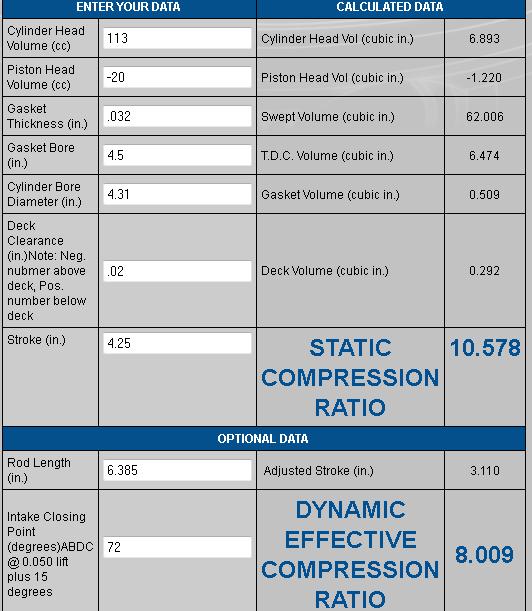
looking at the charts and doing some basic calculations we find that max piston speed should most likely be kept to about 4250 fps to provide durability and thats about 6000rpm with the 4.25" stroke on a 496, we will try to keep the quench at about .040-.044 and the dynamic compression near 8:1 ,averaging the calculator results we find that port cross section can be a minimum of 3.2 sq inches and a max near 4 sq inches,if we don,t want to have port stall or low port velocities, so lets pick about 3.6 sq inches as a compromise, middle ground. if we use a 2.3" intake valve on that 496 we have 62 cubic inches per cylinder and find the calculators say we need a tight 107-108 lsa, (we might want a slightly wider LSA to get the idle a bit smoother, and big block rollers with tighter than 106 LSA are hard to find) and a .680-.690 valve lift to maximize port fill efficiency, with a .50 mach port speed
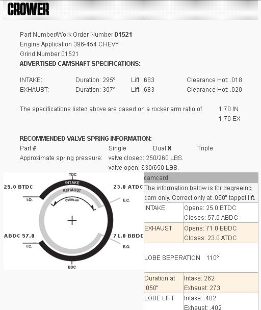
looking at the charts we see the duration of the cam will most likely fall in the 245-260 duration @ .050 lift range, for a street cars engine to maintain max mid rpm torque.
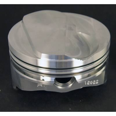
so at that point we know we need a cam and head port and combustion chamber and compression combo that matches that range, we can find a wide range of piston dome or dish sizes so lets look at head flow also, youll want about a 20cc-25cc dome piston to get the 10.5:1 compression and correct static and dynamic compression, obviously things like head gasket and combustion chamber and dome must be tweaked during calculation to find the ideal combo as components selected effect results

http://www.summitracing.com/parts/UEM-IC789-060/
ic789-060_w.jpg

kbcalc.jpg

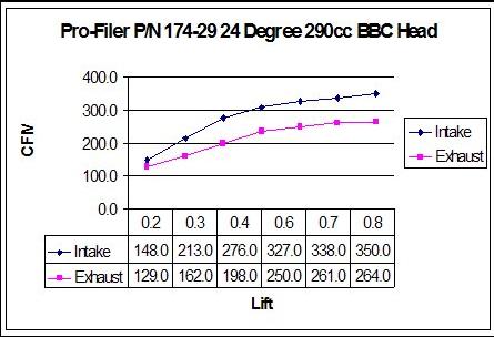
AIR FLOW RESEARCH 290cc
http://www.airflowresearch.com/index.php?cPath=68_121

TRICKFLOW 280cc
http://static.trickflow.com/global/imag ... %20280.pdf
http://www.trickflow.com/partdetail.asp ... toview=sku

PROFILER 290cc
290pro.jpg


HERE, above youll see A couple GOOD CHOICEs IN THIS CASE, as they flow 340cfm with mild clean-up at that .680 valve lift
01521crowerroller.jpg

heres the roller cam Id select for that application


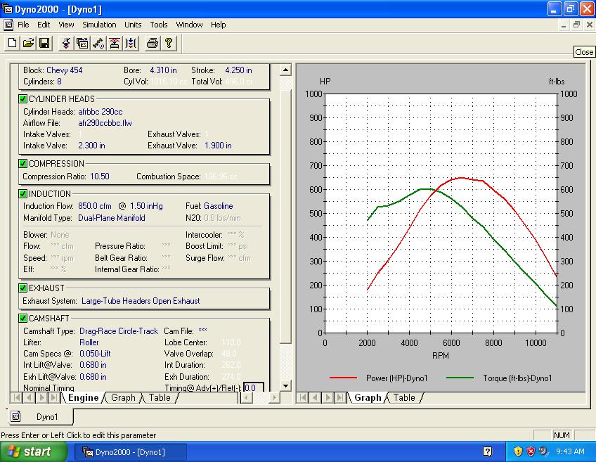
290ccafr496.jpg

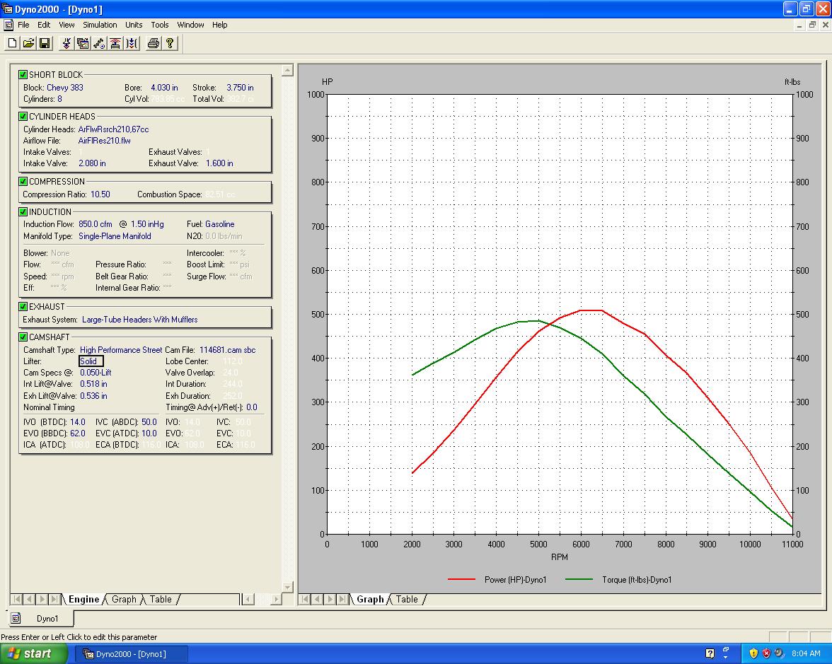
heres DD2000 wild guess at potential results of that combo
http://garage.grumpysperformance.com/index.php?threads/dynamic-vs-static-compression.727/

keep in mind the piston can,t compress anything until both valves seat, and seal
you might have a 383 with a listed stroke of 3.75" but the valves don,t seat with the cam below, until the piston is almost 1/2 the distance up toward the cylinder head on the compression stroke

definition.jpg


compec3.png


http://garage.grumpysperformance.com/index.php?threads/how-to-read-a-cam-spec-card.1477/

valves don,t close at BDC, you need to read the cam card for the specs
heres a typical cam card

look at the cam card posted below
notice the intake valve seats near 82 DEGREES AFTER BOTTOM DEAD CENTER
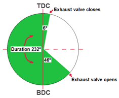
notice the exhaust valve seats near 46 DEGREES AFTER top DEAD CENTER
cambasics.jpg

crane119651.jpg

CAM%20TIMING%20DIAGRAM%20BY%20CAMSHAFT%20ANGLE.jpg


iskypistonloc.jpg


pistonposition2a.jpg


http://www.wallaceracing.com/dynamic-cr.php

http://www.empirenet.com/pkelley2/DynamicCR.html

http://www.not2fast.com/turbo/compression/cranking_pressure.shtml

https://www.uempistons.com/index.ph...e=comp&zenid=1e826335bfac0f356463eabed4958558

https://www.uempistons.com/index.ph...=comp2&zenid=1e826335bfac0f356463eabed4958558

https://www.rbracing-rsr.com/compstaticcalc.html

http://www.diamondracing.net/tools/
related threads and links

http://performancetrends.com/pfa.htm

http://users.erols.com/srweiss/tablehdc.htm

http://performancetrends.com/Engine-Analyzer-Pro.htm
 
Last edited by a moderator:
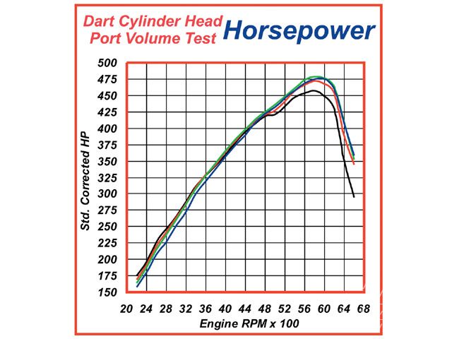
HERE IS A RESPONSE TONY FROM AIR FLOW RESEARCH POSTED CONCERNING A CAMS LSA, AND ITS EFFECT ON THE ENGINES POWER CURVE

"Ive made huge power with good heads and modest lobes on wide LSA's

The better the heads the wider the LSA to reduce over-scavenging.

There is no golden rule for every application.....if I were camming a car on a short oval track I would most certainly tighten the LSA and shorten the duration to bring the power in early and have it explode out of a corner but there are always trade offs in camshaft design and that same situation wont run as hard upstairs as a similar cam on a wider LSA (keeping in mind the wider LSA choice wont make as much peak torque of course or come of of that same corner quite as hard).

Guys, alot of this is driven by the intake closing point....arguably the most important event in camshaft design although they all play a role. A narrow LSA closes its intake valve earlier allowing the piston more time to build cylinder pressure, but at high RPM, when the charge velocity is high allowing it to still fill the cylinder if the valve is still open and of couse the dwell time to grab that next gulp of air is low, it NEEDS and is benefited from a later intake closing event.

How about a 346 pump gas piece with a 224 HR cam.....it made 550 HP at 6400 and carried to 7000. What helped make that possible was a reaaally wide street friendly 114 LSA which was installed with the hopes of actually passing smog here in CA.

The late intake closing point "fooled" the engine into thinking it had a larger cam than it did and it helped carry power fairly flat to 7K or so. While I admit it would have made more peak torque with a more narrow LSA, its street manners would have suffered a tad (emissions certainly taking a hit) and it wouldn't have made as much average power IMO although it was no slouch even with the wide lobe sep making 470 ft/lbs at 4900 or so. That engine made 1.36 ft/lbs per cube and almost 1.6 HP per cube and you could lug it around a corner in your neighborhood at 1000 RPM in 3rd gear without any protest. It just missed passing smog btw....hell if coolant temp was hotter it would have likely passed, it was that close.

Personally, I tend to favor wider LSA cams in both drag cars and street cars and for similar reasons (and FWIW, I'm all about "narrow" in applications that are RPM limited or simply need to make brutal midrange torque at the expense of high RPM power).

A street car is either putting around town at low RPM where a wide LSA cam can improve idle quality and drivability or its getting wrung out banging off the rev limiter hopefully utilizing its top end charge and big power against the guy in the next lane (be it at the track or a lonely stretch of highway).

A pure drag car I like for similar reasons (a focus on horsepower mainly), utilizing the wider LSA (and typical additional duration) to hang that torque curve really far out (and based on the mathematics increase HP notably which is driven by RPM and torque), build a bunch of high RPM power adding alot to the average power the package generates because the engine's power curve will be alot flatter upstairs with that type of set-up.

I readily admit that peak torque and low midrange torque will suffer in both applications I mentioned (street and pure drag) with this approach to camshaft design but I don't care because if we are discussing an acceleration contest, a drag race of any sort, the engine that produces the highest average power, assuming the car is geared and set up properly to harness it, will always win. Torque is for pulling your motor home up a grade....it has no impact on acceleration whatsoever....its only impact is how it effects and creates the power curve at hand.

This of course is another topic that could take up its own ten page thread but once you understand that (and realize its true), it makes it easier to see that horsepower is where you need to set your sights on maximizing. You know why the Moroso slide rule doesn't ask you to input torque into it to figure out what your "X" weight car might run down the dragstrip? IT DOESNT MATTER that's why.....only horsepower and more specifically average horsepower and weight....that's it (and a little aerodynamics in the really fast cars). The car with the highest power to weight ratio wins assuming similar driving talent, traction, car set-up, etc. Its not a torque to weight ratio.....POWER to weight ratio is the holy grail to everything that drives all of us to read these threads and mod our cars (assuming acceleration is the nirvana you crave)

Look....its pretty obvious my philosophy goes against the grain (in this thread at least) and I mean no disrespect to anyone, and specifically Chris Straub who is a bright guy and a valued member here and a guy Ive hung out with and done business with for years (I probably met Chris at a tradeshow with AFR about a decade or so ago). But the fact of the matter is we are all entitled to our opinions and my opinions have been formed by seeing alot of this stuff on the dyno and running and trying alot of this stuff in my own hot rods. Ive been in the right places to experience alot of this (years at SSRE seeing countless combinations get dyno'ed, over a decade heading up R&D at AFR) and have been enamored with the internal combustion engine for a long time as most or some of you have as well I'm sure.

Chris, or anyone honestly hanging there hat on the narrow LSA thing, you mentioned a 511 that made 650 at 6500 or so a few posts back that had modest duration and a tight 107 ish LSA.

Had we cammed the same motor say five degrees larger on both intake and exhaust and cut the cam on a 110 LSA, what do you think might have happened? Its a sincere question that I would love to get other opinions on

My thoughts are it would have made more vacuum (or right about the same) and more peak power with the largest power gains in the curve past peak power at the obviously higher shift point the new combination would dictate (guessing 500 RPM higher). For the sake of a conversation, lets forget about valve float and assume a solid roller valve train or optimized hyd. roller). If I'm right, that package would have notably more average power and therefore have the potential to run faster down the dragstrip if the car was geared and driven properly to keep the engine in its sweet spot (might even need a looser converter but so be it....basically a car optimized to take advantage of that power curve).

Now I readily admit my hypothetical scenario above would see a sizable loss of low RPM torque.....and a modest loss of peak torque but my guess is at 5000-5500 or so the torque curves would have crossed and the cam with the wider LSA and additional duration would have started to shine from there forward with the gap steadily increasing till shift point.

Granted, if the goal was a beast of an engine that was to only see 6500 max, the original cam choice nailed it, but if "X" drivability and the desire to make the most power were the target (without capping RPM), I would think a different cam might be better suited to that.

Lots of ways to skin a cat for sure.....lots of theory and various approaches to a common goal and I hope all of you take this in the manner it was intended and that is to stir the pot a little and get a healthy technical discussion going that makes it interesting for those following this. It would take alot of convincing for me to switch gears and I suspect the feeling is similar in the other camp, but I think alot of this is driven by what your actually setting out to do. For me my goals are clear cut.....I wont the most HP in a package that's friendly to drive (street car goals)....if Im going drag racing I want the most power at the RPM Im willing to turn it....some of that determined by budget and the quality of the parts but I don't give a rats azz about peak torque.....only making the most power that I can and setting up and gearing the car to take the most advantage of exactly that.

Time to start calling it a night.....SORRY FOR THE NOVEL guys....I can only hope it was interesting enough to read


Cheers,
Tony "
 
Good Reading Grumpy. Thanks.
Read some more links later today.
Like the way you prioritize links you deem most important.
Top to bottom order.

Tony Mamo is smart from AFR.

He misses out what other aspects are taking place inside of s performance race engine.

You cover the groundwork better than all online Grumpy.

Few ever talk about Peak Volumemetric efficiency Numbers of 98-130% Normally aspirated that can be obtainable. Water brake or Electric Shunt Eddy Current brake engine dyno measured
BSFC # too

Warren Brownfield changed the Hotrod world.
Not AFR.
AFR uses his research & work.
Started in 1970.
 
Warren Brownfield was contracted to Hand Port Cylinder Heads for Pontiac's SCCA Trans Am Race series.
Pontiac Ram Air 4 "614" heads.
The 303 Giant intake port Ram Air 5 Tunnel port head would not comeon hard till 8,500 RPM'S.
Races lost in 1969.
Warren had his choice of heads to use & port.
He chose the 614 Ram Air 4.
1970-1/2 Midel year out for 2nd year Pontiac Trans Am.
Engine pulled super hard throughout the powerband.
180cc stock intake port volume.
Jerry Titus of Racing Fame driving the newly rededigned Trans Am.
Accident. He died behind the wheel of his TA.

Warren Brownfield took his experience learned
Started Brownfield Racing Cylinder Heads.
Thingd changed forever n the SBC Hotrod Race World.

Brian R.
 
most of you guys know Im an old geezer that still remembers buying cams from crane cams when they were located in hallandale Florida on Dixie highway
http://www.pbase.com/image/94649615
and I well remember BROWNFIELD cylinder heads advertized in the back of hot rod magazine and GENERAL KINETICS CAMS
which were in the late 1970-1980s the hot ticket, at some point in the mid 1980s brownfield was merged WITH or purchased by AIR FLOW RESEARCH
http://www.flickr.com/photos/lightning7 ... /lightbox/

HERES A RELATED POST BY TONY AT AFR
I have typed this on various boards and I will type it again here

Heads are the star of the show....everything else plays a supporting role with the camshaft certainly the "lead" in the various supporting roles to consider (induction, exhaust, fuel system, ignition, etc.)

With a really great set of heads you can almost miss every other player in the build and still have above average results when the smoke clears.

Miss the heads though and you can nail everything else in the build and only produce so-so results.

Heads represent the greatest restriction in the airflow pipeline and due to that fact represent the largest source of all your gains.

Look into any high end form of motor sports and you will see the most prep time and attention is focused on the heads (when discussing the engine build at least).

Alot of folks think any of the big name heads will produce similar results and that is a fallacy (the better amongst them do narrow the gap considerably though)...they want to believe that because the price is less some of the time but in the end you typically get what you pay for.

The stuff I do in the afterhours at home is for the guys that understand that and are willing to pay that little extra to get the "ten-tenths" from them so to speak....to gain an added edge that most folks dont have....I have to assume most of the people I help recognize the role they play.

I spend a ludicrous amount of time prepping the heads for a personal build (and toiling over a zillion other details as well)....but the cylinder heads without a doubt are the cornerstone/foundation of every build."
 
If You haven't noticed Grumpy, I like , admire, & respect old Geezers.
Because they lived it, Raced hard , and have much experience

Crane Cams is back.
Several NHRA Super Stock Records set using Crane grinds in Poncho Pontiac V8 engines .
Smokey Yunick used Crane Cams in NASCAR winning engines .

I was taught by an old timer.
Why I have rhe knowledge in my brain.

Been looking for Original Brownfield 180 heads
Never ported or repaired .
New Old Stock Preferred .
Nothing else desired.
$$$ Set aside to but when I find them.
Rare Now.

I don't care what my generation uses. AFR195's.
Good for them.
They still loose the drag race against a hot running 5.0 Mustang 306ci Tremec 5-speed with 4.10 gears.
Turned high 10's. 1/4 mile.
Normally aspurated. No nitrous.
Trickflow street heads used .
 
Back
Top