is the VATS anti theft system making you nuts?
the key here is thinking logically and
the lost art of
" isolate and test"
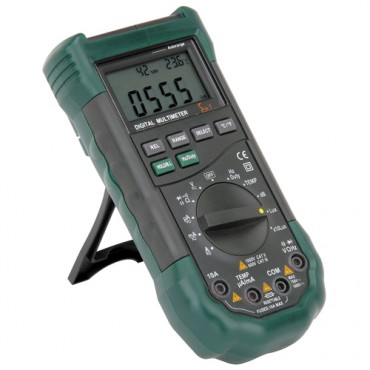 http://www.harborfreight.com/5-in-1-dig ... 98674.html
https://www.corvettemods.com/C4-Cor...MIrPnk2-C-5AIVkobACh2ruQpsEAQYAiABEgLDEvD_BwE
frequent non- starts can be caused by the vats system....
http://www.corvetteactioncenter.com/kb/ ... eft+System
Vehicle Anti-Theft System (VATS)
As you may already know, some of the TPI systems were used on vehicles on which GM implemented a security feature known as VATS. It stands for Vehicle Anti-Theft System. When first introduced by GM on the 1988 Corvette, vehicle theft was reported to have dropped by 30%. This was a simple, and effective system in its time. However, it is an annoying feature when trying to install TPI on a vehicle that does not have a VATS system installed.
How It WorksThe idea behind it is very simple. The ignition key has a "chip" (just a resistor) installed on it, which can be easily seen. When you attempt to turn the ignition ON, the resistance of the chip is measured, and compared to the value stored in the VATS decoder module. If they are the same, a signal is sent to the ECM telling it to fire the injectors (pin F10 for the 1227730 ECM, and pin B6 for the 1227165 ECM). At the same time, the starter enable relay will be energized by the VATS decoder module. If the wrong resistance is read, then the signal will not be sent to the ECM, the starter enable relay will not be energized, and the injectors will not fire. Additionally, a code 46 will be shown. This code will not be stored in the ECM's memory, and is only present while the conditions for a code 46 are present. The module will shut down for 2 to 4 minutes. During this time, any attempts to start the vehicle will not work. If the ignition switch is turned during this time, the timer will restart even if a key with the correct resistance is used.
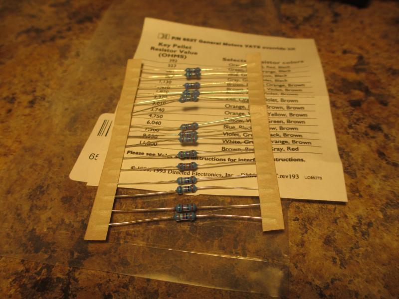
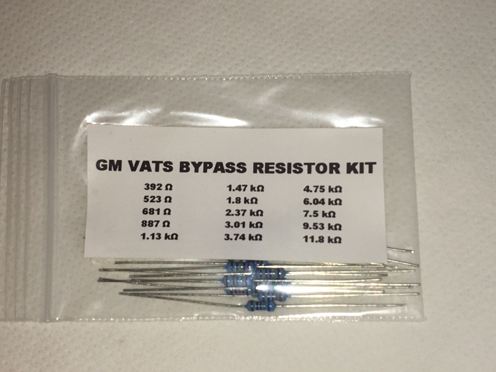
There are 15 possible resistance values that were used by GM.
402 ohms (acceptable range 386-438)
523 ohms (acceptable range 502-564)
681 ohms (acceptable range 650-728)
887 ohms (acceptable range 850-942)
1130 ohms (acceptable range 1085-1195)
1470 ohms (acceptable range 1411-1549)
1870 ohms (acceptable range 1795-1965)
2370 ohms (acceptable range 2275-2485)
3010 ohms (acceptable range 2890-3150)
3740 ohms (acceptable range 3590-3910)
4750 ohms (acceptable range 4560-4960)
6040 ohms (acceptable range 5798-6302)
7500 ohms (acceptable range 7200-7820)
9530 ohms (acceptable range 9149-9931)
11800 ohms (acceptable range 11328-12292)
What It Was Used On
The contents of the PROM is what decides whether or not the ECM is expecting a signal from a VATS decoder module. Some proms have it enabled, some have them disabled. The PROMS that have it enabled can be reprogrammed to disable VATS. If you would like to know if VATS is going to be a problem for your TPI install, the following will be helpful. The information below is broken down by ECM number.
1227730 and 1227727All factory PROMS had VATS enabled. If you are installing TPI on a vehicle that already has a VATS system installed (like a 1990 Camaro RS for example), then you do not need to disable VATS from the PROM. If you are using a Speed Density computer on a vehicle that does not have a VATS system installed (most applications) then you will need to have VATS disabled in the PROM. If you need this service performed on your PROM, contact us for more details.
1227165All the factory PROMs used on 1989 models had VATS enabled. In addition, the 1988 Corvettes, and most 1988 Trans Ams had VATS enabled. If you are installing TPI on a vehicle that already has a VATS system installed (like a 1990 Camaro RS for example), then you do not need to disable VATS from the PROM. The only time you will need to disable VATS is if your PROM came from one of the models mentioned above, and you do not have a VATS system in your vehicle. If you need this service performed on your PROM, contact us for more details.
If your prom came from anything other than the models mentioned above, then it does not have VATS enabled. In this case, you can run your PROM without any modifications.
1226870
None of the models which used this ECM had VATS enabled.
theres a great deal more info in the links and threads provided here
BTW before you go nuts chasing what you assume is a VATS related starter issue verify all your fuses and the battery cables are in good condition, I just went thru this with a guy that insisted his vats system was keeping him from starting the car intermittently, it turned out his problem was caused by
(his alternator was marginal, putting out just 13 volts)
and his battery cable ends were corroded
http://www.vatssucks.com/
viewtopic.php?f=36&t=3453&p=9143&hilit=vats#p9143
http://www.bakerelectronix.com/products_vats/
viewtopic.php?f=36&t=3453&p=9165&hilit=vats#p9165
viewtopic.php?f=36&t=63&p=3403&hilit=vats+resistor#p3403
http://vats.likeabigdog.com/
http://www.thirdgen.org/vats
http://www.thirdgen.org/vats_passkey_system
http://wiki.answers.com/Q/How_can_you_b ... VAT_device
http://tpiparts.net/vehicle_anti_theft_system__vats_/
Vehicle Anti-Theft System (VATS)
QUOTE
"As you may already know, some of the TPI systems were used on vehicles on which GM implemented a security feature known as VATS. It stands for Vehicle Anti-Theft System. When first introduced by GM on the 1988 Corvette, vehicle theft was reported to have dropped by 30%. This was a simple, and effective system in its time. However, it is an annoying feature when trying to install TPI on a vehicle that does not have a VATS system installed.
How It Works
The idea behind it is very simple. The ignition key has a "chip" (just a resistor) installed on it, which can be easily seen. When you attempt to turn the ignition ON, the resistance of the chip is measured, and compared to the value stored in the VATS decoder module. If they are the same, a signal is sent to the ECM telling it to fire the injectors (pin F10 for the 1227730 ECM, and pin B6 for the 1227165 ECM). At the same time, the starter enable relay will be energized by the VATS decoder module. If the wrong resistance is read, then the signal will not be sent to the ECM, the starter enable relay will not be energized, and the injectors will not fire. Additionally, a code 46 will be shown. This code will not be stored in the ECM's memory, and is only present while the conditions for a code 46 are present. The module will shut down for 2 to 4 minutes. During this time, any attempts to start the vehicle will not work. If the ignition switch is turned during this time, the timer will restart even if a key with the correct resistance is used.
There are 15 possible resistance values that were used by GM.
402 ohms (acceptable range 386-438)
523 ohms (acceptable range 502-564)
681 ohms (acceptable range 650-728)
887 ohms (acceptable range 850-942)
1130 ohms (acceptable range 1085-1195)
1470 ohms (acceptable range 1411-1549)
1870 ohms (acceptable range 1795-1965)
2370 ohms (acceptable range 2275-2485)
3010 ohms (acceptable range 2890-3150)
3740 ohms (acceptable range 3590-3910)
4750 ohms (acceptable range 4560-4960)
6040 ohms (acceptable range 5798-6302)
7500 ohms (acceptable range 7200-7820)
9530 ohms (acceptable range 9149-9931)
11800 ohms (acceptable range 11328-12292)
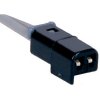
Locate the red wire under the driver's kick panel that comes from the steering column. Inside this will be two white wires and if you follow them you'll come to a plug. Insert your key in the ignition and read the resistance on the two white wires (inside the red wire) coming from the steering column.
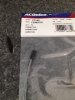
Armed with that useful piece of information....got to Radio Shack and get a resistor that is very close to the same value. Just a couple of percent either way will be fine. Insert the resistor in the plug that you disconnected earlier. Insert it in the end of the plug that doesn't go to the steering column.
Your car will now think that it has the correct key in it all the time. The anti-theft feature will be gone but your car will start every time.
An easier fix would be to get a new key cut for your car. Most of the time the key is bad and not the contacts in the ignition switch.
The resistances and the key number you need are listed here. Set your meter to the 1000 ohm scale and read the resistance of your key....right across both contacts on the "pellet". You should be close to one of these values.
1- 0.402
2- 0.523
3- 0.681
4--0.887
5--1.130
6--1.470
7--1.870
8--2.370
9--3.010
10- 3.740
11 4.750
12-6.040
13-7.500
14-9.530
15-11.801
The key blank number on the left will coincide with the resistance shown. The resistors are about $1.29 for a pack of five. Radio Shack didn't have just one.
What It Was Used On
The contents of the PROM is what decides whether or not the ECM is expecting a signal from a VATS decoder module. Some proms have it enabled, some have them disabled. The PROMS that have it enabled can be reprogrammed to disable VATS. If you would like to know if VATS is going to be a problem for your TPI install, the following will be helpful. The information below is broken down by ECM number.
1227730 and 1227727
All factory PROMS had VATS enabled. If you are installing TPI on a vehicle that already has a VATS system installed (like a 1990 Camaro RS for example), then you do not need to disable VATS from the PROM. If you are using a Speed Density computer on a vehicle that does not have a VATS system installed (most applications) then you will need to have VATS disabled in the PROM. If you need this service performed on your PROM, contact us for more details.
1227165
All the factory PROMs used on 1989 models had VATS enabled. In addition, the 1988 Corvettes, and most 1988 Trans Ams had VATS enabled. If you are installing TPI on a vehicle that already has a VATS system installed (like a 1990 Camaro RS for example), then you do not need to disable VATS from the PROM. The only time you will need to disable VATS is if your PROM came from one of the models mentioned above, and you do not have a VATS system in your vehicle. If you need this service performed on your PROM, contact us for more details.
If your prom came from anything other than the models mentioned above, then it does not have VATS enabled. In this case, you can run your PROM without any modifications.
1226870
None of the models which used this ECM had VATS enabled."
http://www.thirdgen.org/vats
VATS Malfunction Diagnosis and Bypass
Andy89RS Mar 31 2006 - 5:15pm
One of the more common problems with the VATS security systems in the third generation f-bodies is caused by a simple bad connection in the ignition cylinder. The problems start when the wires leading from the contacts in the cylinder to the VATS module develop an intermittent contact or a complete break. This can cause sudden failure to crank, either intermittently or permanently. Due to the nature of the system, manual transmission cars can t even be push started.
DIAGNOSIS:
The first step is to check the resistance of the chip in the key with a multimeter. Write this value down, you ll be needing it later. Next, remove the panel under the dash and look for a pair of yellow wires coming from the steering column and leading to a connector a short distance away. Unplug the connector and with the key in the ignition, measure the resistance at the wires leading from the steering column. The reading should match that of the chip in your key. While the reading might match while the key is in the off position, it will probably change when the key is turned forward. If this happens, the problem is in the ignition cylinder or the wires leading to it. At this point there are two options: Buy a new ignition cylinder and for alot of money or bypass the system for less than a dollar.
BYPASS:
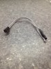
To bypass the system you ll need to buy a resistor with a value matching that of your keys chip at any local electronics store. The easiest way to install this resistor is to cut the wires leading into the column about a foot from the connector. Take this section of wire, strip the ends and solder the resistor in place. Take this section of wire and resistor and simply plug back into the connector under the dash. The VATS module is now fooled into thinking that there is always the correct key in the ignition. Although this does render the security benefits of the VATS system useless, if increased security is desired, the resistor can simply be unplugged, leaving the car disabled until it is reinstalled.
READ these links
http://vats.likeabigdog.com/
http://wiki.xtronics.com/index.php/Resistor_Codes
his chart is for any GM product, Buick, Cadillac, Oldsombile, Chevrolet, and Pontiac that has a VATS key (single or double-sided.)
VATS # (K)OHMS (Set your meter to the 20k ohm setting)
1- 0.402
2- 0.523
3- 0.681
4--0.887
5--1.130
6--1.470
7--1.870
8--2.370
9--3.010
10- 3.740
11 4.750
12-6.040
13-7.500
14-9.530
15-11.801
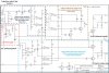
These and most any other vehicle diagram can be found here:
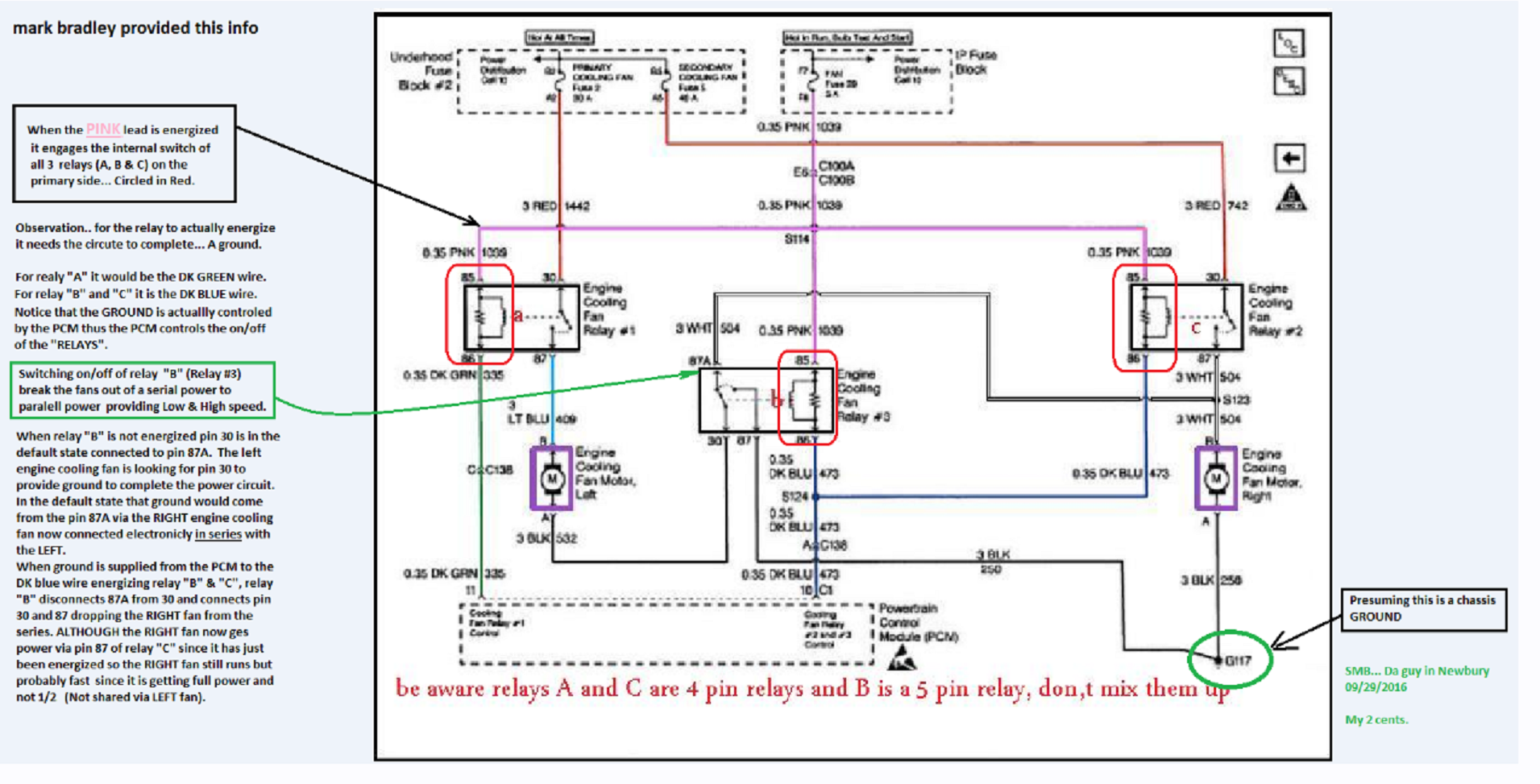
you can,t always trust scanners suggestions either, I recently had a code scanner suggest a cooling fan relay was defective,
replacing it with a known good relay that was working in an identical car had no effect neither relay tested bad either..
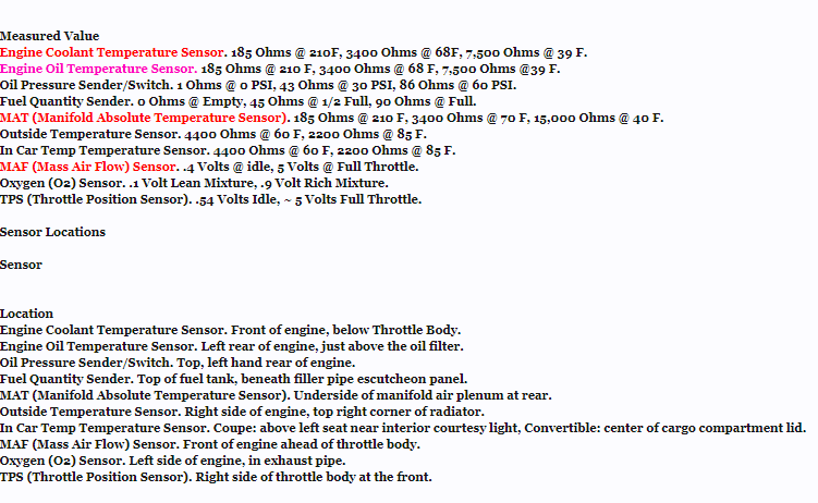
the problem was tracked down to a loose ground and a heat sensor that tested good at its rated ohms resistance, but failed to trigger the relay
experience suggested I test the relay by inserting a resistor of the known rated ohms to trigger the relay into the pigtail that connected to the sensor,
a simple test like that proved the sensor was defective as the fan and relay function with the resistor in the pigtail.
https://www.sparkfun.com/products/10969
https://www.jameco.com/z/GB115-1-8-1-4-and-1-2-Watt-Resistor-Grab-Bag-Tolerances-2-5-10-_134130.html

https://www.diyaudioandvideo.com/Electronics/ResistorColorCodes/
http://www.bulldogsecurity.com/bdnew/ve ... agrams.asp
C4 Wiring Diagrams
Thought this might be helpful to someone..
MODEL YEAR(S)
CORVETTE 1984 -1985
KEY T-HARNESS IMMOBILIZER
N/A N/A GM's VATS ANTI-THEFT System (if Equipped, Ignition Key has Chip) Requires 791 Bypass Module
PART COLOR LOCATION
12 VOLT CONSTANT RED (+) IGNITION SWITCH HARNESS
STARTER YELLOW (+) IGNITION SWITCH HARNESS
STARTER 2 N/A
IGNITION 1 PINK (+) IGNITION SWITCH HARNESS
IGNITION 2 N/A
IGNITION 3 N/A
ACCESSORY/HEATER BLOWER 1 ORANGE (+) IGNITION SWITCH HARNESS
ACCESSORY/HEATER BLOWER 2 N/A
KEYSENSE N/A
PARKING LIGHTS ( - ) N/A
PARKING LIGHTS ( + ) BROWN (+) @ HEADLIGHT SWITCH
POWER LOCK LIGHT BLUE (TYPE A) IN EITHER KICK PANEL
POWER UNLOCK BLACK (TYPE A) IN EITHER KICK PANEL
DOOR TRIGGER WHITE (-) @ UNDER DASH LIGHT
DOMELIGHT SUPERVISION USE DOOR TRIGGER, Requires #775 Relay
TRUNK RELEASE BROWN (-), Requires #775 Relay @ HATCH RELEASE SWITCH
SLIDING POWER DOOR N/A
HORN BLACK (-) @ STEERING COLUMN HARNESS
TACH WHITE or PURPLE/WHITE @ IGNITION COIL or DISTRIBUTOR
WAIT TO START LIGHT N/A
BRAKE WHITE (+) @ SWITCH ABOVE BRAKE PEDAL
FACTORY ALARM DISARM LIGHT GREEN (-) IN DRIVERS KICK PANEL
ANTI-THEFT See NOTE *1 GM's VATS System @ Ignition Switch
EXTRA INFORMATION
NOTE *1 The VATS (Vehicle Anti-Theft System) wire may be (2) thin YELLOW wires, (2) thin TAN wires or (2) thin WHITE wires, these wires are usually in a ORANGE or BLACK HEAT SHRINK TUBE, but at times are left out of the tube and ran by themselves up under the dash to the Security Module under the Dash.
MODEL YEAR(S)
CORVETTE 1986 -1989
KEY T-HARNESS IMMOBILIZER
N/A N/A GM's VATS ANTI-THEFT System (if Equipped) Requires 791 Bypass Module
PART COLOR LOCATION
12 VOLT CONSTANT RED (+) IGNITION SWITCH HARNESS
STARTER YELLOW (+) IGNITION SWITCH HARNESS
STARTER 2 N/A
IGNITION 1 PINK (+) IGNITION SWITCH HARNESS
IGNITION 2 N/A
IGNITION 3 N/A
ACCESSORY/HEATER BLOWER 1 ORANGE (+) IGNITION SWITCH HARNESS
ACCESSORY/HEATER BLOWER 2 BROWN (+) IGNITION SWITCH HARNESS
KEYSENSE N/A
PARKING LIGHTS ( - ) N/A
PARKING LIGHTS ( + ) BROWN (+) @ HEADLIGHT SWITCH
POWER LOCK LIGHT BLUE (TYPE C) IN EITHER KICK PANEL
POWER UNLOCK BLACK (TYPE C) IN EITHER KICK PANEL
DOOR TRIGGER WHITE (-) @ UNDER DASH LIGHT, See NOTE *3
DOMELIGHT SUPERVISION USE DOOR TRIGGER, Requires #775 Relay
TRUNK RELEASE BLACK (+), Requires #775 Relay @ DECK RELEASE RELAY, See NOTE *2
SLIDING POWER DOOR N/A
HORN BLACK (-) @ STEERING COLUMN HARNESS
TACH WHITE or PURPLE/WHITE @ IGNITION COIL or DISTRIBUTOR
WAIT TO START LIGHT N/A
BRAKE WHITE (+) @ SWITCH ABOVE BRAKE PEDAL
FACTORY ALARM DISARM LIGHT GREEN (-) IN EITHER KICK PANEL
ANTI-THEFT See NOTE *1 GM's VATS System @ Ignition Switch
EXTRA INFORMATION
NOTE *1 The VATS (Vehicle Anti-Theft System) wire may be (2) thin YELLOW wires, (2) thin TAN wires or (2) thin WHITE wires, these wires are usually in a ORANGE or BLACK HEAT SHRINK TUBE, but at times are left out of the tube and ran by themselves up under the dash to the Security Module under the Dash.
NOTE *2 the DECK RELEASE Relay is located at the right rear corner of the luggage compartment.
NOTE *3 use the Passenger DOOR LOCK Switch as the MASTER SWITCH when testing.
MODEL YEAR(S)
CORVETTE 1990 -1993
KEY T-HARNESS IMMOBILIZER
N/A N/A GM's VATS ANTI-THEFT System (if Equipped, Ignition Key has Chip) Requires 791 Bypass Module
PART COLOR LOCATION
12 VOLT CONSTANT RED (+) IGNITION SWITCH HARNESS
STARTER YELLOW (+) IGNITION SWITCH HARNESS
STARTER 2 N/A
IGNITION 1 PINK (+) IGNITION SWITCH HARNESS
IGNITION 2 N/A
IGNITION 3 N/A
ACCESSORY/HEATER BLOWER 1 ORANGE (+) IGNITION SWITCH HARNESS
ACCESSORY/HEATER BLOWER 2 N/A
KEYSENSE N/A
PARKING LIGHTS ( - ) N/A
PARKING LIGHTS ( + ) BROWN (+) @ HEADLIGHT SWITCH
POWER LOCK LIGHT BLUE (TYPE C) See NOTE *2 IN EITHER KICK PANEL
POWER UNLOCK BLACK (TYPE C) See NOTE *2 IN EITHER KICK PANEL
DOOR TRIGGER BLACK/WHITE (-) and BLACK/YELLOW (-) Use both, See NOTE *3 IN EACH KICK PANEL
DOMELIGHT SUPERVISION WHITE (-), Requires #775 Relay @ UNDER DASH LIGHT
TRUNK RELEASE BROWN (-), Requires #775 Relay @ HATCH RELEASE SWITCH
SLIDING POWER DOOR N/A
HORN BLACK (-) @ STEERING COLUMN HARNESS
TACH WHITE or PURPLE/WHITE @ IGNITION COIL
WAIT TO START LIGHT N/A
BRAKE WHITE (+) or LIGHT BLUE (+) @ SWITCH ABOVE BRAKE PEDAL
FACTORY ALARM DISARM LIGHT GREEN (-) IN EITHER KICK PANEL
ANTI-THEFT See NOTE *1 GM's VATS System @ Ignition Switch
EXTRA INFORMATION
NOTE *1 The VATS (Vehicle Anti-Theft System) wire may be (2) thin YELLOW wires, (2) thin TAN wires or (2) thin WHITE wires, these wires are usually in a ORANGE or BLACK HEAT SHRINK TUBE, but at times are left out of the tube and ran by themselves up under the dash to the Security Module under the Dash.
NOTE *2 This is a TYPE "C" DOOR LOCKING SYSTEM, the PASSENGER switch is the MASTER switch for testing.
NOTE *3 The BLACK/WHITE (-) is for the DRIVERS DOOR and the BLACK/YELLOW (-) is for the PASSENGER DOOR, use both and DIODE ISOLATE when connecting to an ALARM SYSTEM.
MODEL YEAR(S)
CORVETTE 1994 -1996
KEY T-HARNESS IMMOBILIZER
N/A N/A GM's VATS ANTI-THEFT System, Ignition Key has Chip, Requires 791 Bypass Module
PART COLOR LOCATION
12 VOLT CONSTANT RED (+) IGNITION SWITCH HARNESS
STARTER YELLOW (+) IGNITION SWITCH HARNESS
STARTER 2 N/A
IGNITION 1 PINK (+) IGNITION SWITCH HARNESS
IGNITION 2 N/A
IGNITION 3 N/A
ACCESSORY/HEATER BLOWER 1 ORANGE (+) IGNITION SWITCH HARNESS
ACCESSORY/HEATER BLOWER 2 N/A
KEYSENSE N/A
PARKING LIGHTS ( - ) N/A
PARKING LIGHTS ( + ) BROWN (+) @ HEADLIGHT SWITCH
POWER LOCK RED/BLACK (TYPE C) See NOTE *2 IN EITHER KICK PANEL
POWER UNLOCK ORANGE/BLACK (TYPE C) See NOTE *2 IN EITHER KICK PANEL
DOOR TRIGGER BLACK/WHITE (-) and GRAY/BLACK (-) Use both, See NOTE *3 IN EACH KICK PANEL
DOMELIGHT SUPERVISION BLACK/WHITE (-), Requires #775 Relay IN DRIVERS KICK PANEL
TRUNK RELEASE LIGHT BLUE (-), Requires #775 Relay @ HATCH RELEASE SWITCH
SLIDING POWER DOOR N/A
HORN BLACK (-) @ STEERING COLUMN HARNESS
TACH RED/BLACK @ ECM, above the BATTERY
WAIT TO START LIGHT N/A
BRAKE WHITE (+) or LIGHT BLUE (+) @ SWITCH ABOVE BRAKE PEDAL
FACTORY ALARM DISARM GREEN (-) IN EITHER KICK PANEL
ANTI-THEFT See NOTE *1 GM's VATS System @ Ignition Switch
EXTRA INFORMATION
NOTE *1 The VATS (Vehicle Anti-Theft System) wire may be (2) thin YELLOW wires, (2) thin TAN wires or (2) thin WHITE wires, these wires are usually in a ORANGE or BLACK HEAT SHRINK TUBE, but at times are left out of the tube and ran by themselves up under the dash to the Security Module under the Dash.
NOTE *2 This is a TYPE "C" DOOR LOCKING SYSTEM, the PASSENGER switch is the MASTER switch for testing.
NOTE *3 The BLACK/WHITE (-) is for the DRIVERS DOOR and the GREY/BLACK (-) is for the PASSENGER DOOR, use both and DIODE ISOLATE when connecting to an ALARM SYSTEM.
the key here is thinking logically and
the lost art of
" isolate and test"
https://www.corvettemods.com/C4-Cor...MIrPnk2-C-5AIVkobACh2ruQpsEAQYAiABEgLDEvD_BwE
frequent non- starts can be caused by the vats system....
http://www.corvetteactioncenter.com/kb/ ... eft+System
Vehicle Anti-Theft System (VATS)
As you may already know, some of the TPI systems were used on vehicles on which GM implemented a security feature known as VATS. It stands for Vehicle Anti-Theft System. When first introduced by GM on the 1988 Corvette, vehicle theft was reported to have dropped by 30%. This was a simple, and effective system in its time. However, it is an annoying feature when trying to install TPI on a vehicle that does not have a VATS system installed.
How It WorksThe idea behind it is very simple. The ignition key has a "chip" (just a resistor) installed on it, which can be easily seen. When you attempt to turn the ignition ON, the resistance of the chip is measured, and compared to the value stored in the VATS decoder module. If they are the same, a signal is sent to the ECM telling it to fire the injectors (pin F10 for the 1227730 ECM, and pin B6 for the 1227165 ECM). At the same time, the starter enable relay will be energized by the VATS decoder module. If the wrong resistance is read, then the signal will not be sent to the ECM, the starter enable relay will not be energized, and the injectors will not fire. Additionally, a code 46 will be shown. This code will not be stored in the ECM's memory, and is only present while the conditions for a code 46 are present. The module will shut down for 2 to 4 minutes. During this time, any attempts to start the vehicle will not work. If the ignition switch is turned during this time, the timer will restart even if a key with the correct resistance is used.
There are 15 possible resistance values that were used by GM.
402 ohms (acceptable range 386-438)
523 ohms (acceptable range 502-564)
681 ohms (acceptable range 650-728)
887 ohms (acceptable range 850-942)
1130 ohms (acceptable range 1085-1195)
1470 ohms (acceptable range 1411-1549)
1870 ohms (acceptable range 1795-1965)
2370 ohms (acceptable range 2275-2485)
3010 ohms (acceptable range 2890-3150)
3740 ohms (acceptable range 3590-3910)
4750 ohms (acceptable range 4560-4960)
6040 ohms (acceptable range 5798-6302)
7500 ohms (acceptable range 7200-7820)
9530 ohms (acceptable range 9149-9931)
11800 ohms (acceptable range 11328-12292)
What It Was Used On
The contents of the PROM is what decides whether or not the ECM is expecting a signal from a VATS decoder module. Some proms have it enabled, some have them disabled. The PROMS that have it enabled can be reprogrammed to disable VATS. If you would like to know if VATS is going to be a problem for your TPI install, the following will be helpful. The information below is broken down by ECM number.
1227730 and 1227727All factory PROMS had VATS enabled. If you are installing TPI on a vehicle that already has a VATS system installed (like a 1990 Camaro RS for example), then you do not need to disable VATS from the PROM. If you are using a Speed Density computer on a vehicle that does not have a VATS system installed (most applications) then you will need to have VATS disabled in the PROM. If you need this service performed on your PROM, contact us for more details.
1227165All the factory PROMs used on 1989 models had VATS enabled. In addition, the 1988 Corvettes, and most 1988 Trans Ams had VATS enabled. If you are installing TPI on a vehicle that already has a VATS system installed (like a 1990 Camaro RS for example), then you do not need to disable VATS from the PROM. The only time you will need to disable VATS is if your PROM came from one of the models mentioned above, and you do not have a VATS system in your vehicle. If you need this service performed on your PROM, contact us for more details.
If your prom came from anything other than the models mentioned above, then it does not have VATS enabled. In this case, you can run your PROM without any modifications.
1226870
None of the models which used this ECM had VATS enabled.
theres a great deal more info in the links and threads provided here
BTW before you go nuts chasing what you assume is a VATS related starter issue verify all your fuses and the battery cables are in good condition, I just went thru this with a guy that insisted his vats system was keeping him from starting the car intermittently, it turned out his problem was caused by
(his alternator was marginal, putting out just 13 volts)
and his battery cable ends were corroded
http://www.vatssucks.com/
viewtopic.php?f=36&t=3453&p=9143&hilit=vats#p9143
http://www.bakerelectronix.com/products_vats/
viewtopic.php?f=36&t=3453&p=9165&hilit=vats#p9165
viewtopic.php?f=36&t=63&p=3403&hilit=vats+resistor#p3403
http://vats.likeabigdog.com/
http://www.thirdgen.org/vats
http://www.thirdgen.org/vats_passkey_system
http://wiki.answers.com/Q/How_can_you_b ... VAT_device
http://tpiparts.net/vehicle_anti_theft_system__vats_/
Vehicle Anti-Theft System (VATS)
QUOTE
"As you may already know, some of the TPI systems were used on vehicles on which GM implemented a security feature known as VATS. It stands for Vehicle Anti-Theft System. When first introduced by GM on the 1988 Corvette, vehicle theft was reported to have dropped by 30%. This was a simple, and effective system in its time. However, it is an annoying feature when trying to install TPI on a vehicle that does not have a VATS system installed.
How It Works
The idea behind it is very simple. The ignition key has a "chip" (just a resistor) installed on it, which can be easily seen. When you attempt to turn the ignition ON, the resistance of the chip is measured, and compared to the value stored in the VATS decoder module. If they are the same, a signal is sent to the ECM telling it to fire the injectors (pin F10 for the 1227730 ECM, and pin B6 for the 1227165 ECM). At the same time, the starter enable relay will be energized by the VATS decoder module. If the wrong resistance is read, then the signal will not be sent to the ECM, the starter enable relay will not be energized, and the injectors will not fire. Additionally, a code 46 will be shown. This code will not be stored in the ECM's memory, and is only present while the conditions for a code 46 are present. The module will shut down for 2 to 4 minutes. During this time, any attempts to start the vehicle will not work. If the ignition switch is turned during this time, the timer will restart even if a key with the correct resistance is used.
There are 15 possible resistance values that were used by GM.
402 ohms (acceptable range 386-438)
523 ohms (acceptable range 502-564)
681 ohms (acceptable range 650-728)
887 ohms (acceptable range 850-942)
1130 ohms (acceptable range 1085-1195)
1470 ohms (acceptable range 1411-1549)
1870 ohms (acceptable range 1795-1965)
2370 ohms (acceptable range 2275-2485)
3010 ohms (acceptable range 2890-3150)
3740 ohms (acceptable range 3590-3910)
4750 ohms (acceptable range 4560-4960)
6040 ohms (acceptable range 5798-6302)
7500 ohms (acceptable range 7200-7820)
9530 ohms (acceptable range 9149-9931)
11800 ohms (acceptable range 11328-12292)
Locate the red wire under the driver's kick panel that comes from the steering column. Inside this will be two white wires and if you follow them you'll come to a plug. Insert your key in the ignition and read the resistance on the two white wires (inside the red wire) coming from the steering column.
Armed with that useful piece of information....got to Radio Shack and get a resistor that is very close to the same value. Just a couple of percent either way will be fine. Insert the resistor in the plug that you disconnected earlier. Insert it in the end of the plug that doesn't go to the steering column.
Your car will now think that it has the correct key in it all the time. The anti-theft feature will be gone but your car will start every time.
An easier fix would be to get a new key cut for your car. Most of the time the key is bad and not the contacts in the ignition switch.
The resistances and the key number you need are listed here. Set your meter to the 1000 ohm scale and read the resistance of your key....right across both contacts on the "pellet". You should be close to one of these values.
1- 0.402
2- 0.523
3- 0.681
4--0.887
5--1.130
6--1.470
7--1.870
8--2.370
9--3.010
10- 3.740
11 4.750
12-6.040
13-7.500
14-9.530
15-11.801
The key blank number on the left will coincide with the resistance shown. The resistors are about $1.29 for a pack of five. Radio Shack didn't have just one.
What It Was Used On
The contents of the PROM is what decides whether or not the ECM is expecting a signal from a VATS decoder module. Some proms have it enabled, some have them disabled. The PROMS that have it enabled can be reprogrammed to disable VATS. If you would like to know if VATS is going to be a problem for your TPI install, the following will be helpful. The information below is broken down by ECM number.
1227730 and 1227727
All factory PROMS had VATS enabled. If you are installing TPI on a vehicle that already has a VATS system installed (like a 1990 Camaro RS for example), then you do not need to disable VATS from the PROM. If you are using a Speed Density computer on a vehicle that does not have a VATS system installed (most applications) then you will need to have VATS disabled in the PROM. If you need this service performed on your PROM, contact us for more details.
1227165
All the factory PROMs used on 1989 models had VATS enabled. In addition, the 1988 Corvettes, and most 1988 Trans Ams had VATS enabled. If you are installing TPI on a vehicle that already has a VATS system installed (like a 1990 Camaro RS for example), then you do not need to disable VATS from the PROM. The only time you will need to disable VATS is if your PROM came from one of the models mentioned above, and you do not have a VATS system in your vehicle. If you need this service performed on your PROM, contact us for more details.
If your prom came from anything other than the models mentioned above, then it does not have VATS enabled. In this case, you can run your PROM without any modifications.
1226870
None of the models which used this ECM had VATS enabled."
http://www.thirdgen.org/vats
VATS Malfunction Diagnosis and Bypass
Andy89RS Mar 31 2006 - 5:15pm
One of the more common problems with the VATS security systems in the third generation f-bodies is caused by a simple bad connection in the ignition cylinder. The problems start when the wires leading from the contacts in the cylinder to the VATS module develop an intermittent contact or a complete break. This can cause sudden failure to crank, either intermittently or permanently. Due to the nature of the system, manual transmission cars can t even be push started.
DIAGNOSIS:
The first step is to check the resistance of the chip in the key with a multimeter. Write this value down, you ll be needing it later. Next, remove the panel under the dash and look for a pair of yellow wires coming from the steering column and leading to a connector a short distance away. Unplug the connector and with the key in the ignition, measure the resistance at the wires leading from the steering column. The reading should match that of the chip in your key. While the reading might match while the key is in the off position, it will probably change when the key is turned forward. If this happens, the problem is in the ignition cylinder or the wires leading to it. At this point there are two options: Buy a new ignition cylinder and for alot of money or bypass the system for less than a dollar.
BYPASS:
To bypass the system you ll need to buy a resistor with a value matching that of your keys chip at any local electronics store. The easiest way to install this resistor is to cut the wires leading into the column about a foot from the connector. Take this section of wire, strip the ends and solder the resistor in place. Take this section of wire and resistor and simply plug back into the connector under the dash. The VATS module is now fooled into thinking that there is always the correct key in the ignition. Although this does render the security benefits of the VATS system useless, if increased security is desired, the resistor can simply be unplugged, leaving the car disabled until it is reinstalled.
READ these links
http://vats.likeabigdog.com/
http://wiki.xtronics.com/index.php/Resistor_Codes
his chart is for any GM product, Buick, Cadillac, Oldsombile, Chevrolet, and Pontiac that has a VATS key (single or double-sided.)
VATS # (K)OHMS (Set your meter to the 20k ohm setting)
1- 0.402
2- 0.523
3- 0.681
4--0.887
5--1.130
6--1.470
7--1.870
8--2.370
9--3.010
10- 3.740
11 4.750
12-6.040
13-7.500
14-9.530
15-11.801
These and most any other vehicle diagram can be found here:
you can,t always trust scanners suggestions either, I recently had a code scanner suggest a cooling fan relay was defective,
replacing it with a known good relay that was working in an identical car had no effect neither relay tested bad either..
the problem was tracked down to a loose ground and a heat sensor that tested good at its rated ohms resistance, but failed to trigger the relay
experience suggested I test the relay by inserting a resistor of the known rated ohms to trigger the relay into the pigtail that connected to the sensor,
a simple test like that proved the sensor was defective as the fan and relay function with the resistor in the pigtail.
https://www.sparkfun.com/products/10969
https://www.jameco.com/z/GB115-1-8-1-4-and-1-2-Watt-Resistor-Grab-Bag-Tolerances-2-5-10-_134130.html
https://www.diyaudioandvideo.com/Electronics/ResistorColorCodes/
http://www.bulldogsecurity.com/bdnew/ve ... agrams.asp
C4 Wiring Diagrams
Thought this might be helpful to someone..
MODEL YEAR(S)
CORVETTE 1984 -1985
KEY T-HARNESS IMMOBILIZER
N/A N/A GM's VATS ANTI-THEFT System (if Equipped, Ignition Key has Chip) Requires 791 Bypass Module
PART COLOR LOCATION
12 VOLT CONSTANT RED (+) IGNITION SWITCH HARNESS
STARTER YELLOW (+) IGNITION SWITCH HARNESS
STARTER 2 N/A
IGNITION 1 PINK (+) IGNITION SWITCH HARNESS
IGNITION 2 N/A
IGNITION 3 N/A
ACCESSORY/HEATER BLOWER 1 ORANGE (+) IGNITION SWITCH HARNESS
ACCESSORY/HEATER BLOWER 2 N/A
KEYSENSE N/A
PARKING LIGHTS ( - ) N/A
PARKING LIGHTS ( + ) BROWN (+) @ HEADLIGHT SWITCH
POWER LOCK LIGHT BLUE (TYPE A) IN EITHER KICK PANEL
POWER UNLOCK BLACK (TYPE A) IN EITHER KICK PANEL
DOOR TRIGGER WHITE (-) @ UNDER DASH LIGHT
DOMELIGHT SUPERVISION USE DOOR TRIGGER, Requires #775 Relay
TRUNK RELEASE BROWN (-), Requires #775 Relay @ HATCH RELEASE SWITCH
SLIDING POWER DOOR N/A
HORN BLACK (-) @ STEERING COLUMN HARNESS
TACH WHITE or PURPLE/WHITE @ IGNITION COIL or DISTRIBUTOR
WAIT TO START LIGHT N/A
BRAKE WHITE (+) @ SWITCH ABOVE BRAKE PEDAL
FACTORY ALARM DISARM LIGHT GREEN (-) IN DRIVERS KICK PANEL
ANTI-THEFT See NOTE *1 GM's VATS System @ Ignition Switch
EXTRA INFORMATION
NOTE *1 The VATS (Vehicle Anti-Theft System) wire may be (2) thin YELLOW wires, (2) thin TAN wires or (2) thin WHITE wires, these wires are usually in a ORANGE or BLACK HEAT SHRINK TUBE, but at times are left out of the tube and ran by themselves up under the dash to the Security Module under the Dash.
MODEL YEAR(S)
CORVETTE 1986 -1989
KEY T-HARNESS IMMOBILIZER
N/A N/A GM's VATS ANTI-THEFT System (if Equipped) Requires 791 Bypass Module
PART COLOR LOCATION
12 VOLT CONSTANT RED (+) IGNITION SWITCH HARNESS
STARTER YELLOW (+) IGNITION SWITCH HARNESS
STARTER 2 N/A
IGNITION 1 PINK (+) IGNITION SWITCH HARNESS
IGNITION 2 N/A
IGNITION 3 N/A
ACCESSORY/HEATER BLOWER 1 ORANGE (+) IGNITION SWITCH HARNESS
ACCESSORY/HEATER BLOWER 2 BROWN (+) IGNITION SWITCH HARNESS
KEYSENSE N/A
PARKING LIGHTS ( - ) N/A
PARKING LIGHTS ( + ) BROWN (+) @ HEADLIGHT SWITCH
POWER LOCK LIGHT BLUE (TYPE C) IN EITHER KICK PANEL
POWER UNLOCK BLACK (TYPE C) IN EITHER KICK PANEL
DOOR TRIGGER WHITE (-) @ UNDER DASH LIGHT, See NOTE *3
DOMELIGHT SUPERVISION USE DOOR TRIGGER, Requires #775 Relay
TRUNK RELEASE BLACK (+), Requires #775 Relay @ DECK RELEASE RELAY, See NOTE *2
SLIDING POWER DOOR N/A
HORN BLACK (-) @ STEERING COLUMN HARNESS
TACH WHITE or PURPLE/WHITE @ IGNITION COIL or DISTRIBUTOR
WAIT TO START LIGHT N/A
BRAKE WHITE (+) @ SWITCH ABOVE BRAKE PEDAL
FACTORY ALARM DISARM LIGHT GREEN (-) IN EITHER KICK PANEL
ANTI-THEFT See NOTE *1 GM's VATS System @ Ignition Switch
EXTRA INFORMATION
NOTE *1 The VATS (Vehicle Anti-Theft System) wire may be (2) thin YELLOW wires, (2) thin TAN wires or (2) thin WHITE wires, these wires are usually in a ORANGE or BLACK HEAT SHRINK TUBE, but at times are left out of the tube and ran by themselves up under the dash to the Security Module under the Dash.
NOTE *2 the DECK RELEASE Relay is located at the right rear corner of the luggage compartment.
NOTE *3 use the Passenger DOOR LOCK Switch as the MASTER SWITCH when testing.
MODEL YEAR(S)
CORVETTE 1990 -1993
KEY T-HARNESS IMMOBILIZER
N/A N/A GM's VATS ANTI-THEFT System (if Equipped, Ignition Key has Chip) Requires 791 Bypass Module
PART COLOR LOCATION
12 VOLT CONSTANT RED (+) IGNITION SWITCH HARNESS
STARTER YELLOW (+) IGNITION SWITCH HARNESS
STARTER 2 N/A
IGNITION 1 PINK (+) IGNITION SWITCH HARNESS
IGNITION 2 N/A
IGNITION 3 N/A
ACCESSORY/HEATER BLOWER 1 ORANGE (+) IGNITION SWITCH HARNESS
ACCESSORY/HEATER BLOWER 2 N/A
KEYSENSE N/A
PARKING LIGHTS ( - ) N/A
PARKING LIGHTS ( + ) BROWN (+) @ HEADLIGHT SWITCH
POWER LOCK LIGHT BLUE (TYPE C) See NOTE *2 IN EITHER KICK PANEL
POWER UNLOCK BLACK (TYPE C) See NOTE *2 IN EITHER KICK PANEL
DOOR TRIGGER BLACK/WHITE (-) and BLACK/YELLOW (-) Use both, See NOTE *3 IN EACH KICK PANEL
DOMELIGHT SUPERVISION WHITE (-), Requires #775 Relay @ UNDER DASH LIGHT
TRUNK RELEASE BROWN (-), Requires #775 Relay @ HATCH RELEASE SWITCH
SLIDING POWER DOOR N/A
HORN BLACK (-) @ STEERING COLUMN HARNESS
TACH WHITE or PURPLE/WHITE @ IGNITION COIL
WAIT TO START LIGHT N/A
BRAKE WHITE (+) or LIGHT BLUE (+) @ SWITCH ABOVE BRAKE PEDAL
FACTORY ALARM DISARM LIGHT GREEN (-) IN EITHER KICK PANEL
ANTI-THEFT See NOTE *1 GM's VATS System @ Ignition Switch
EXTRA INFORMATION
NOTE *1 The VATS (Vehicle Anti-Theft System) wire may be (2) thin YELLOW wires, (2) thin TAN wires or (2) thin WHITE wires, these wires are usually in a ORANGE or BLACK HEAT SHRINK TUBE, but at times are left out of the tube and ran by themselves up under the dash to the Security Module under the Dash.
NOTE *2 This is a TYPE "C" DOOR LOCKING SYSTEM, the PASSENGER switch is the MASTER switch for testing.
NOTE *3 The BLACK/WHITE (-) is for the DRIVERS DOOR and the BLACK/YELLOW (-) is for the PASSENGER DOOR, use both and DIODE ISOLATE when connecting to an ALARM SYSTEM.
MODEL YEAR(S)
CORVETTE 1994 -1996
KEY T-HARNESS IMMOBILIZER
N/A N/A GM's VATS ANTI-THEFT System, Ignition Key has Chip, Requires 791 Bypass Module
PART COLOR LOCATION
12 VOLT CONSTANT RED (+) IGNITION SWITCH HARNESS
STARTER YELLOW (+) IGNITION SWITCH HARNESS
STARTER 2 N/A
IGNITION 1 PINK (+) IGNITION SWITCH HARNESS
IGNITION 2 N/A
IGNITION 3 N/A
ACCESSORY/HEATER BLOWER 1 ORANGE (+) IGNITION SWITCH HARNESS
ACCESSORY/HEATER BLOWER 2 N/A
KEYSENSE N/A
PARKING LIGHTS ( - ) N/A
PARKING LIGHTS ( + ) BROWN (+) @ HEADLIGHT SWITCH
POWER LOCK RED/BLACK (TYPE C) See NOTE *2 IN EITHER KICK PANEL
POWER UNLOCK ORANGE/BLACK (TYPE C) See NOTE *2 IN EITHER KICK PANEL
DOOR TRIGGER BLACK/WHITE (-) and GRAY/BLACK (-) Use both, See NOTE *3 IN EACH KICK PANEL
DOMELIGHT SUPERVISION BLACK/WHITE (-), Requires #775 Relay IN DRIVERS KICK PANEL
TRUNK RELEASE LIGHT BLUE (-), Requires #775 Relay @ HATCH RELEASE SWITCH
SLIDING POWER DOOR N/A
HORN BLACK (-) @ STEERING COLUMN HARNESS
TACH RED/BLACK @ ECM, above the BATTERY
WAIT TO START LIGHT N/A
BRAKE WHITE (+) or LIGHT BLUE (+) @ SWITCH ABOVE BRAKE PEDAL
FACTORY ALARM DISARM GREEN (-) IN EITHER KICK PANEL
ANTI-THEFT See NOTE *1 GM's VATS System @ Ignition Switch
EXTRA INFORMATION
NOTE *1 The VATS (Vehicle Anti-Theft System) wire may be (2) thin YELLOW wires, (2) thin TAN wires or (2) thin WHITE wires, these wires are usually in a ORANGE or BLACK HEAT SHRINK TUBE, but at times are left out of the tube and ran by themselves up under the dash to the Security Module under the Dash.
NOTE *2 This is a TYPE "C" DOOR LOCKING SYSTEM, the PASSENGER switch is the MASTER switch for testing.
NOTE *3 The BLACK/WHITE (-) is for the DRIVERS DOOR and the GREY/BLACK (-) is for the PASSENGER DOOR, use both and DIODE ISOLATE when connecting to an ALARM SYSTEM.
Last edited by a moderator: