Question - 'Limiting Port Velocity' vs Intake Runner Sizing

enigma57

reliable source of info
Grumpy...... Regarding intake port cross section and port velocity...... I have a question for you, as I am confused over seemingly inconsistent data......

* First, old Weber technical manuals I have read over state that "the 'optimum gas speed' for best flow with Weber carburettors is 325 fps. Interesting enough, this might explain why ofttimes, increasing the size of the intake valves does not result in increased power and at times, may actually result in decreased power".

* Further, Larry Meaux (the fellow in Louisiana who designed the pipemax program) has stated that in his experience, "Anything over or near to 350 fps will probably cause a premature Choke in a Live engine." This was in the context of a discussion regarding cross section transitions in the intake runners and inside the head at short turn radius or pushrod pinch point. So those two statements seem to corroborate one another.

Now where I get confused is where I read elsewhere that high port velocity up to 0.55 mach is OK...... Mach 1 being 761.5 mph at sea level...... And 0.55 Mach (flow limit) being 614 fps.

Also...... I plugged some data into Wallace Racing's calculators and this is what I come up with......

* Looking for a solution just under 350 fps port velocity......

http://www.wallaceracing.com/lpv.php

"Your Limiting Port Velocity computed from your Cross Sectional Area of 3.1 sq. in. and Bore of 4.125 in. and Stroke of 4.00 in. and Peak RPM of 4500 is 348.77 fps."

OK, that agrees with Weber tech manuals and Larry Meaux...... BUT......

http://www.wallaceracing.com/runnertorquecalc.php

"2.75 sq. in. = Peak Torque RPM 4,544.26 RPM (calculated)", so I am assuming max HP to be between 5,700 and 6,200 RPMs with peak torque near 4,500 RPM?

* But if I go back to......

http://www.wallaceracing.com/lpv.php

"Your Limiting Port Velocity computed from your Cross Sectional Area of 2.75 sq. in. and Bore of 4.125 in. and Stroke of 4.0 in. and Peak RPM of 5500 is 480.52 fps"...... And for "6000 RPM is 524.21 fps."

So, what do I design to at redline?...... Slightly less than 0.55 mach (614 fps)...... Or slightly less than 350 fps?

Also found this...... (Only works in Internet Explorer)......

http://www.velocity-of-sound.com/veloci ... lator3.htm

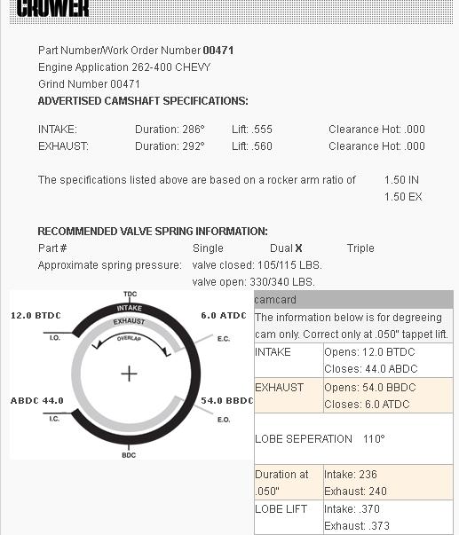
285 deg. adv. duration
3rd Induction wave
4,500 RPM optimum power
1.875" diameter round port = 2.76 sq. in. (seems to agree with Wallace Racing calculator)

Best regards,

Harry

P.S. >>>> This thread is a continuation of the discussion begun here......

viewtopic.php?f=38&t=894

viewtopic.php?f=38&t=894
 
OK for those that might not know what the #$%^ I’m discussing here, read thru the linked info below, but basically a port and runner have both the ability to speed up and control a column of air that ram feeds a cylinder at some rpms if its carefully designed and also its got the potential to restrict that flow into the cylinder, the idea, it to correctly match the cross sectional area to maximize the flow at the desired rpm band where you intend to produce power. larger ports tend to have larger volumes of fuel/air mix stacked between the port entrance and the back of the intake valve, that volume of air has inertia and its hard to get it moving or slow it once it is moving at high velocities, larger ports have slower port flow rates simply because volume is greater and the cylinder they feed contains a piston and valve that requires a lower velocity of air to flow thru that larger port to the cylinder to fill the cylinder volume created when the piston rapidly drops away from tdc on the intake stroke while the air tries to equalize the outside air pressure by flowing thru the intake valve
to keep things really simple keep in mind that 300fps is measured on a flow bench at a steady 28" of water collum as a draw, or vacuum ,as a standard way to measure ports, as engine flow rates vary a great deal with cam timing and displacement and rpm, compression and scavenging efficiency. Without a test standard we can’t compare ports.


heres a chart FROM THE BOOK,HOW TO BUILD BIG-INCH CHEVY SMALL BLOCKS with some common cross sectional port sizes
(measured at the smallest part of the ports)
...........................sq inches........port cc
edelbrock performer rpm ....1.43.............170
vortec......................1.66.............170
tfs195......................1.93.............195
afr 180.....................1.93.............180
afr 195.....................1.98.............195
afr 210.....................2.05.............210
dart pro 200................2.06.............200
dart pro 215................2.14.............215
brodix track 1 .............2.30.............221
dart pro 1 230..............2.40.............230
edelbrock 23 high port .....2.53.............238
edelbrock 18 deg............2.71.............266
tfs 18 deg..................2.80.............250

ok PORT CROSS SECTIONAL AREA and LENGTH need to be calculated in an ideal intake runner config and there’s several factors that need to be looked at, ITS been my experience that you want to keep the port flow rates in the 300fps range or slightly below,durring testing ,once they start to greatly exceed about 325 fps on the flow bench, you start getting inconsistent fuel/air distribution, in an engine, where the flow rates are higher and your dealing with pulses.
first, lets look at exhaust scavenging as you’ll ideally want to have a strong negative pressure help draw the intake charge into the cylinders at the same power band(RPM RANGE) as the intakes tuned for or your effectively missing out on a good deal of the combos potential.
remember the only force packing the cylinders is outside air pressure and some exhaust scavaging, helping to draw durring the overlap in cam timing.
these threads should help and yes most of the info in the sub links
fe008cfd.gif


viewtopic.php?f=56&t=185

viewtopic.php?f=56&t=961

viewtopic.php?f=56&t=495

http://ljs.academicdirect.org/A14/031_049.htm

next port flow, and valve train

viewtopic.php?f=52&t=322&p=722&hilit=+volumetric#p722

viewtopic.php?f=52&t=796

viewtopic.php?f=52&t=975

viewtopic.php?f=52&t=333

viewtopic.php?f=52&t=181

in an VERY overly simplifed form
you can expect the volumetric efficiency to start falling off with that port size and flow rate, both from the restriction to flow due to port restriction and TIME the intake valve remains open is limiting flow simply because as the rpms build the time allowed for flow becomes very limited thru the valve and port for each individual intake charge to flow into the cylinder.
keep in mind the vacuum the port sees varies with cam timing, displacement, rod length, compression ratio, overlap and exhaust scavenging and rpms.
 
Last edited by a moderator:
:D Thanks for taking the time to post that info, Grumpy! Great stuff...... I read through it earlier this evening and it goes a long way towards making this all make sense.

I have been digging around the internet and quietly sitting in on discussions amongst head porters this evening as well and I have finally figured out why there is a seeming discrepancy in the cfs flow numbers generated by the Wallace Racing calculators. Turns out its a fairly simple 'apples to oranges' comparison and my confusion stemmed from my not being familiar with the difference between flow measured at 28" of depression on a typical flow bench...... And flow measured at actual air speed in the port of a 'live' (running) engine (both commonly stated in cubic feet per second).

Seems the 300 fps or 280 fps of desirable velocity that is commonly discussed regarding flow values of ports in heads and manifolds is measured at 28" of depression on a typical flow bench...... So that number is a flow bench number. Flow values measured at 28" are around 1/2 that of actual velocity measured in cu. ft. per second (I am still looking for an exact conversion factor).

However, the higher fps numbers calculated by the Wallace Racing calculator relative to 'Limiting Port Velocity' and port sizing represent actual air speed in the port of a 'live' (running) engine. These actual flow values relate directly to mach or sonic speed...... 0.55 mach (614 cfm at sea level) being max. theoretical flow beyond which 'choke' is likely to occur in the port of a 'live' (running) engine at the pushrod pinch or other such narrowing or transition of the port cross section.

In other words, 600 cfm actual air speed in the port of a 'live' (running) engine = around 300 cfm measured at 28" of depression on a typical flow bench.

Now if only carburettor cfm for both 2bbl and 4bbl carbs were stated in 28" depression as well......

1bbl & 2bbl CFM (3.0 in./HG pressure drop) = 4bbl CFM x 1.414
4bbl CFM (1.5 in./HG pressure drop) = 2bbl CFM / 1.414

To confuse us novices even more, it is my understanding that some carb manufacturers state dry flow values whilst others state wet flow values...... And there are others who do not publish flow values at all.

Perhaps I can locate a conversion factor for either 3.0 in. / HG or 1.5 in. / HG pressure drop to 28" depression. For those of us who do not have a flow bench and cannot flow the carb or EFI throttle body at that same depression...... It would be so much easier relating cfm flow through the throttle bores of the carb or throttle body at WOT...... To flow in the port(s) if all were measured at the same 28" of depression...... Whether the intake has a plenum beneath the carburettor throttle plate(s) supplying air / fuel mixture to multiple cylinders...... Or whether it is a true isolated runner design having no plenum between each individual throttle plate and each individual intake valve in a 2-valve head, for instance.

If all values were standardized at the same 28" depression whether carb or EFI...... And at either dry flow or wet flow values (either apples to apples or oranges to oranges)...... Wet flow intake runner (manifold) / wet flow runner in head...... Or dry flow intake runner (manifold) / wet flow in head, depending upon application...... It would be so much easier to determine the relationship of flow through each port to flow through the carb or EFI throttle body.

So I have learned something new today and will hopefully do so again tomorrow. Say...... Who says you can't teach an old dog new tricks?

Best regards and many thanks,

Harry
 
Thanks, Grumpy! Really appreciate your posting these links. I'll give them a read as soon as I return home tomorrow afternoon.

Best regards,

Harry
 
HARRY Ive got a tendency to think far faster and further ahead than I type, so if I get off on some distracted course or your not following,what i wrote,and want clearification or flat out think IM full of B.S, please PM me and feel free to point out where IM wrong or unclear so I can clearify or correct posted info
look Im may forget to state something or on occasion I might be wrong and we don,t want bad info on the site so work with me, (send a P.M.)
 
:D Hi, Grumpy! Just wanted to thank you for your patience regarding my asking so many questions. My training and job experience is mostly in pipefitting, welding inspection and heavy construction.

When it comes to modifying vehicles for enhanced performance, I am a hobbyist and although I've built more than a few engines and cars over the years, I do not have the wealth of experience that someone who builds engines for race cars and boats day in and day out for their living would have.

Designing and building this IR intake manifold from scratch is something that I have never done before and so I am doing my best to learn from yourself and others the theory behind it so that I can do it right the first time, rather than cobbling something together at random that may not work so well.

Anyway...... You're doing a great job explaining this and providing links we can read over to gain a better understanding of the design principles involved. I wasn't disagreeing with you at all.

Being new to this...... I simply became confused when I attempted to use the Wallace Racing calculators because the velocities stated in their calculator results are so much faster than the 280 - 300 cfs range we were discussing.

I only came to understand after posting my initial question that cfs measured on a flow bench at 28" depression...... The 280 - 300 cfs we are talking about here...... Is around half that of actual air speed in the port of a 'live' (running) engine. And the higher fps numbers calculated by the Wallace Racing calculators represent actual air speed, rather than air speed at 28" depression.

So the 280 - 300 cfs air speed range we are discussing here is a flow bench number measured at 28" depression...... And that equates to 560 - 600 cfs actual air speed in the port of a 'live' (running) engine...... 0.55 mach (theoretical max or 'limiting' port velocity) being 614 cfs at sea level.

:shock: I'll send you a PM the next time I get so confused. I feel like a real dummy for not having understood the difference between the two.

Best regards,

Harry
 
don,t feel bad, remember the port flow changes direction 50 -60 times a second in the upper rpm,s (or more, much more) just due to reversion pulse waves when the valve opens/shuts and in reality that reversion pulse bounces several times between valve closures and the port roof tends to flow faster than the port floor so theres no real easy way to measure the flow rates
accurately even on a flow bench that directly translates to whats going on in an engine.
we measure at a steady flow on a flow bench then we see what works and basically use experience to compare the two different results

theres a great deal of useful info in these links

http://www.velocity-of-sound.com/veloci ... lator3.htm

viewtopic.php?f=27&t=408&p=688&hilit=+bench#p688

http://www.wallaceracing.com/throttle-b ... ameter.php

http://www.wipo.int/pctdb/en/wo.jsp?IA= ... SPLAY=DESC

http://www.installuniversity.com/instal ... 012000.htm

http://www.ztechz.net/id2.html

http://www.knfilters.com/MAF/MAFDevices.htm

http://www.knfilters.com/MAF/massairfindings.htm

http://www.rbracing-rsr.com/runnertorquecalc.html

http://www.bgsoflex.com/intakeln.html

http://www.jsme.or.jp/esd/COMODIA-Procs ... 4_P535.pdf

BTW, that conversion factor your looking for..

and a link to hilborn and kinsler to give you a few ideas


http://www.kinsler.com/page--Manifolds--6.html

http://www.hilborninjection.com/product ... &CatId=174

http://users.erols.com/srweiss/calcplv.htm

http://users.erols.com/srweiss/calcdchg.htm
 
Re: Question - 'Limiting Port Velocity' vs Intake Runner Siz
portvl.png

USE THE CALCULATORS
http://www.rbracing-rsr.com/runnertorquecalc.html
http://www.wallaceracing.com/chokepoint.php
http://www.wallaceracing.com/header_length.php
http://www.wallaceracing.com/chokepoint.php
http://www.rbracing-rsr.com/runnertorquecalc.html
http://www.velocity-of-sound.com/velocity_of_sound/calculator1.htm

portccvshp.jpg

vechart.gif


If your thinking of building a TPI intake based engine,your almost racing a horse wearing hobbles here!
the stock heads flow about 200 cfm , they are very restrictive, it makes very little sense to use an intake that once ported can flow more than 275cfm matched to heads that flow 200-220 cfm, or restrict an engine with a cam that won,t allow air flow much past 5500rpm, matched to an intake that flows well past 6500rpm.
your wasting your time with the stock cams designed to meet the TPI flow characteristics and peaks at about 5500rpm,
the stealth rams designed to flow a good deal more air at a much higher rpm than a TPI, a stock or even mildly ported TPI basically post stalls by 5500rpm,the stealth ram can easily allow 6500rpm or more with the correct cam and heads, gearing etc.
youll want a 3.73:1 rear gear, a 3000 stall converter with a decent trans cooler, or manual trans, or a combo like this won,t work correctly
portedhsr.jpg

a properly ported stealth ram, matched to decent heads
http://www.profilerperformance.com/racing/cylinderheads/sbc-23-degree
heads that can actually use the potential intake flow rates, 30lb-40 lb injectors to supply the required fuel to match the air flow..
crower00471.jpg

and it would sure help if you build a 383 -406 SBC to use the extra air flow potential,with 10.5:1 COMPRESSION OR AT LEAST SELECT HEADS FOR YOUR 350 THAT FLOW AT LEAST 250 CFM AT .500 LIFT AND GET TO 10:1 COMPRESSION MINIMUM
obviously what goes in needs to exit so a decent set of headers and a low restriction exhaust is mandatory
fe008cfd.gif


BTW the stock HOLLEY FUEL PRESSURE REGULATOR ON THE STEALTH RAM, is know to have frequent failures, heres a link to a higher quality unit, part #6547

http://www.kirbanperformance.com/produc ... 36547.html

http://forum.grumpysperformance.com/viewtopic.php?f=52&t=5078&p=18935&hilit=head+flow+numbers#p18935

http://forum.grumpysperformance.com/viewtopic.php?f=52&t=401&p=17237&hilit=head+flow+numbers#p17237

http://forum.grumpysperformance.com/viewtopic.php?f=32&t=5521&p=16619&hilit=head+flow+numbers#p16619

viewtopic.php?f=71&t=662&p=9328#p9328

viewtopic.php?f=44&t=38&hilit=carb+spacer
 
Last edited by a moderator:
Back
Top