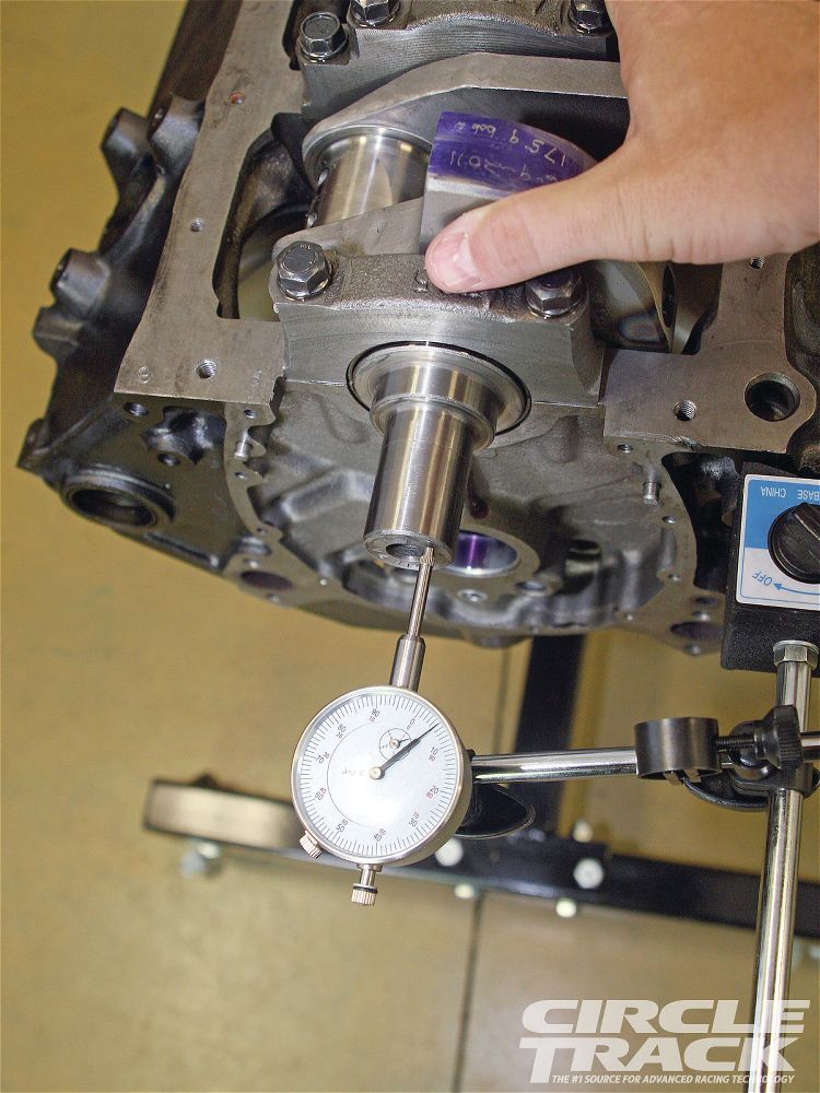
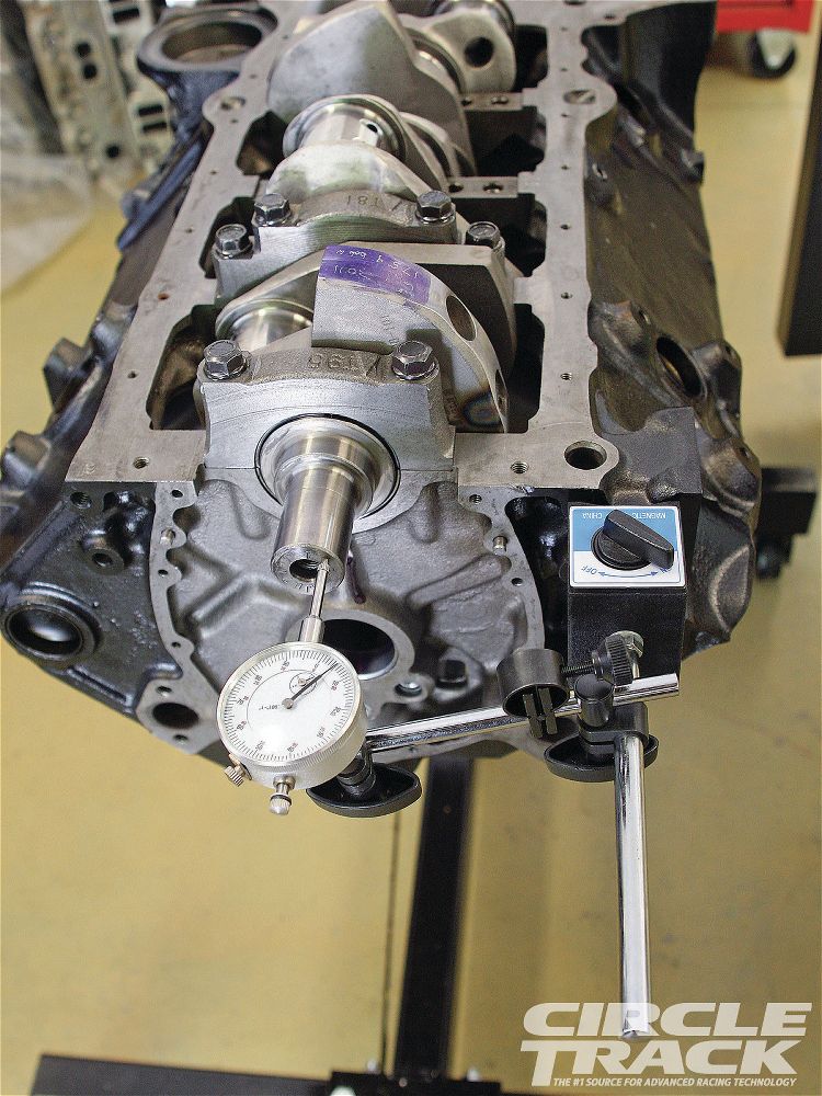
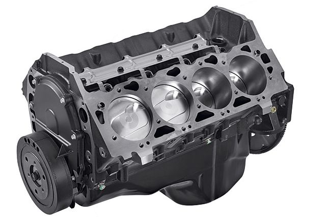
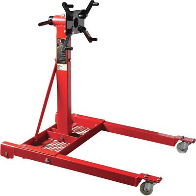
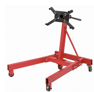
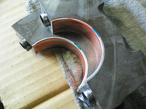
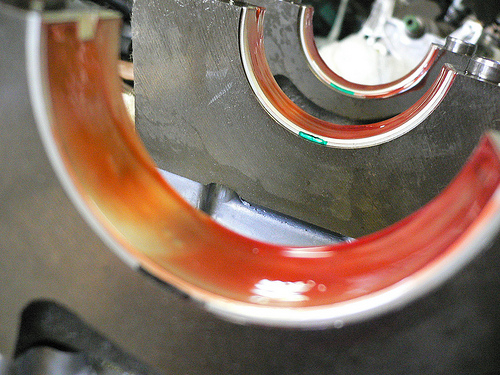
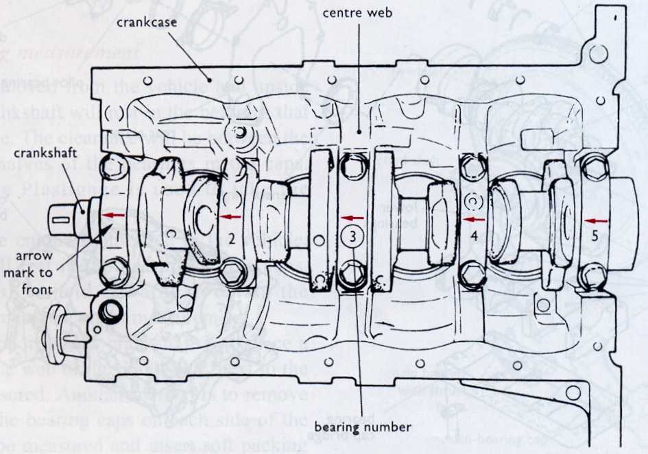
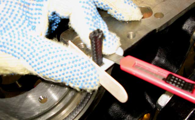
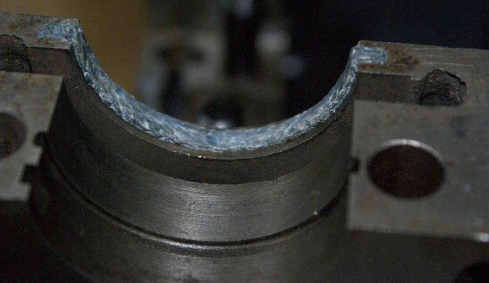
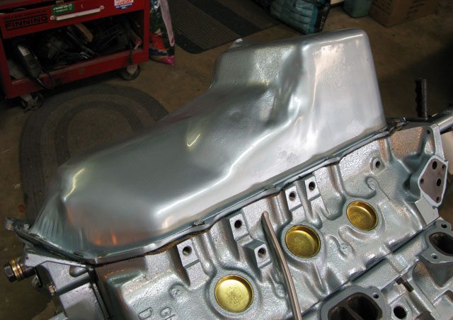
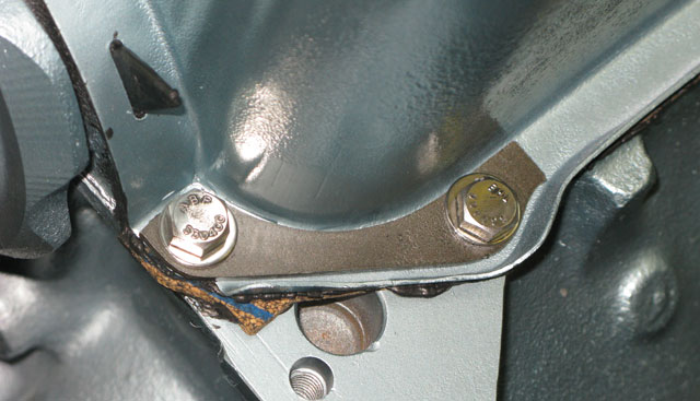
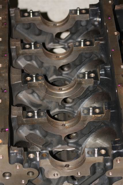
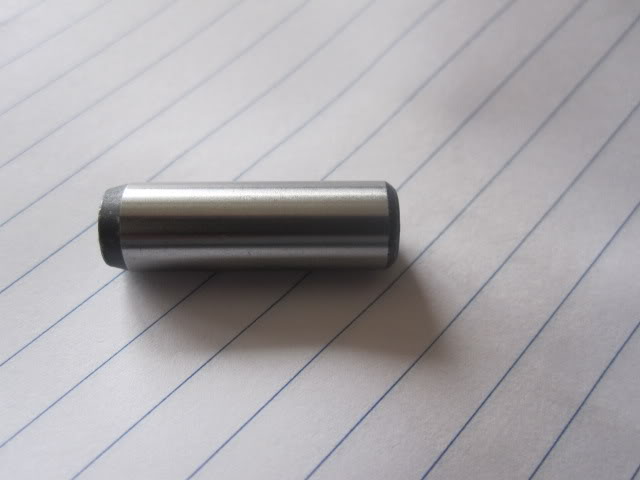
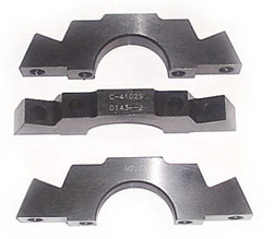
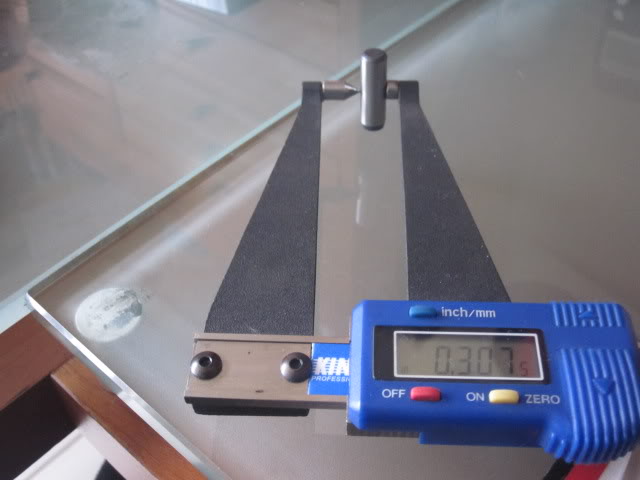
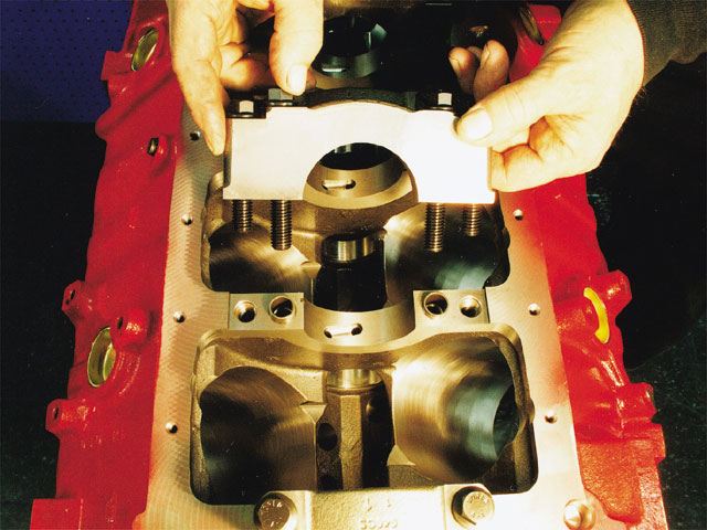
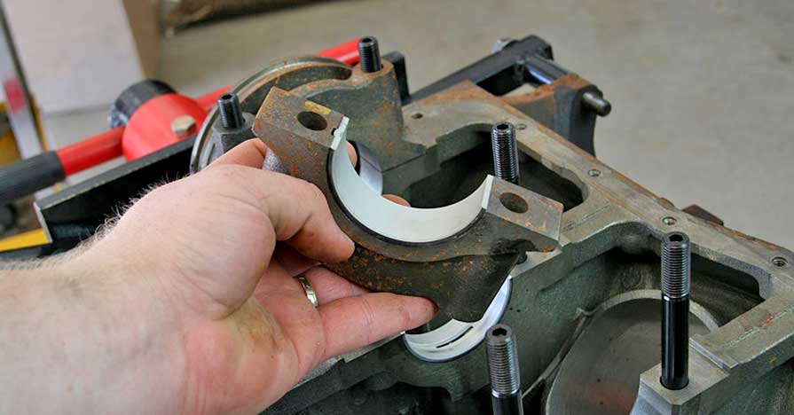
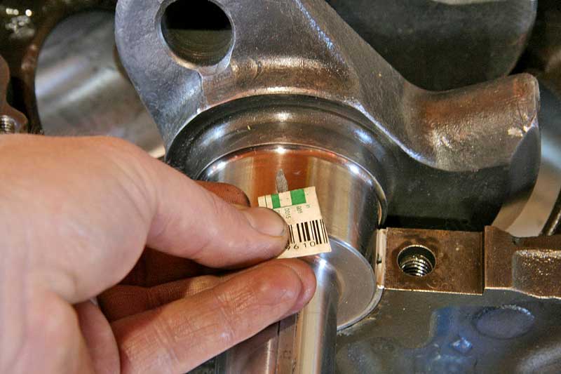
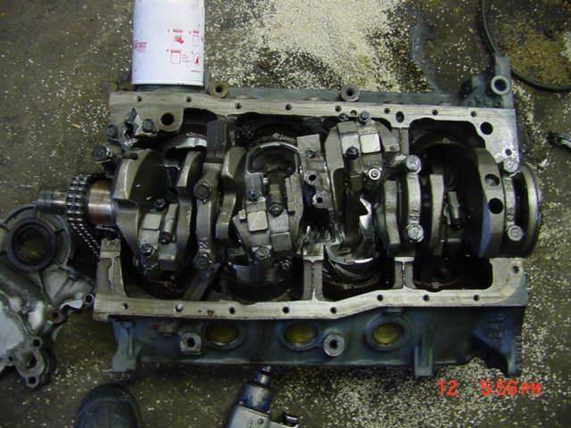
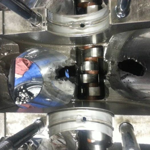
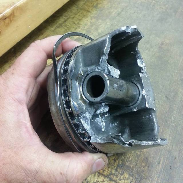
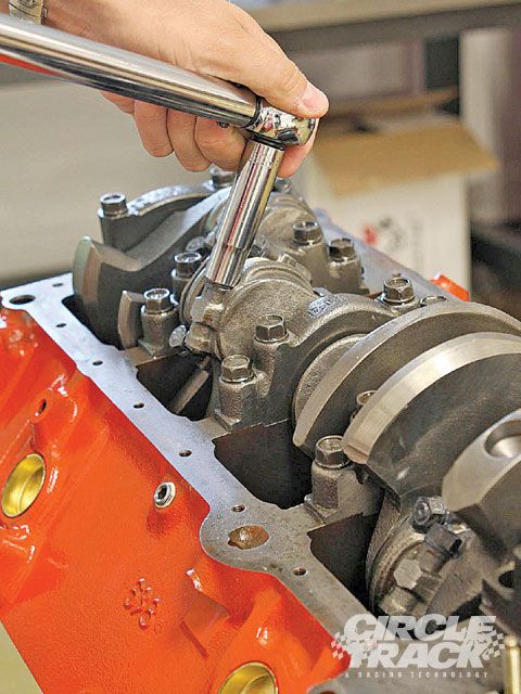
Ok youve just installed your crankshaft in the engine block, with new main bearings and everything's well coated with assembly lube,and oil, and youve torqued down the main caps to spec. in at least three stages, and then gone back and rechecked the studs or bolts per the manufacturers instructions, but you have yet to install the pistons and rods, OK, its time to check the rotational resistance at the first stage, while your assembling the engine on the engine stand.
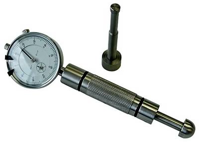
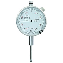
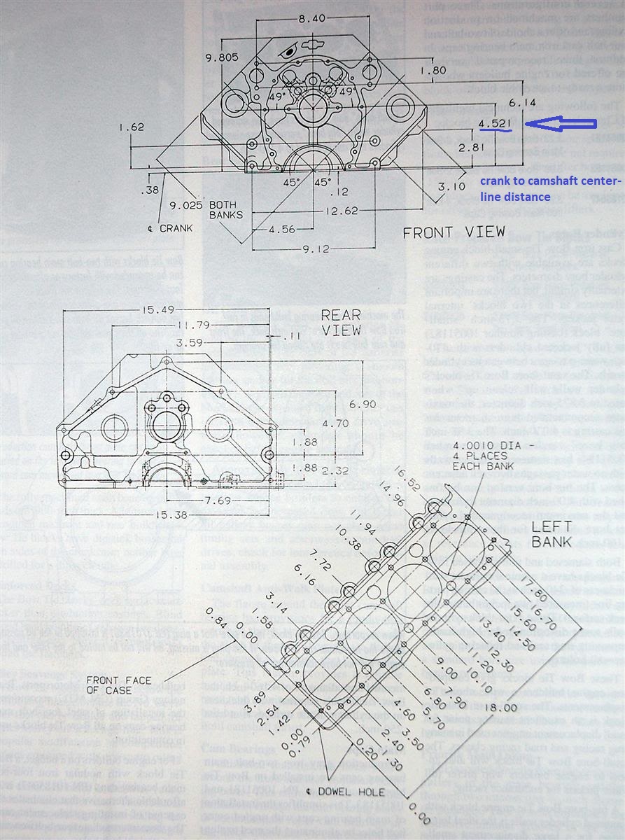
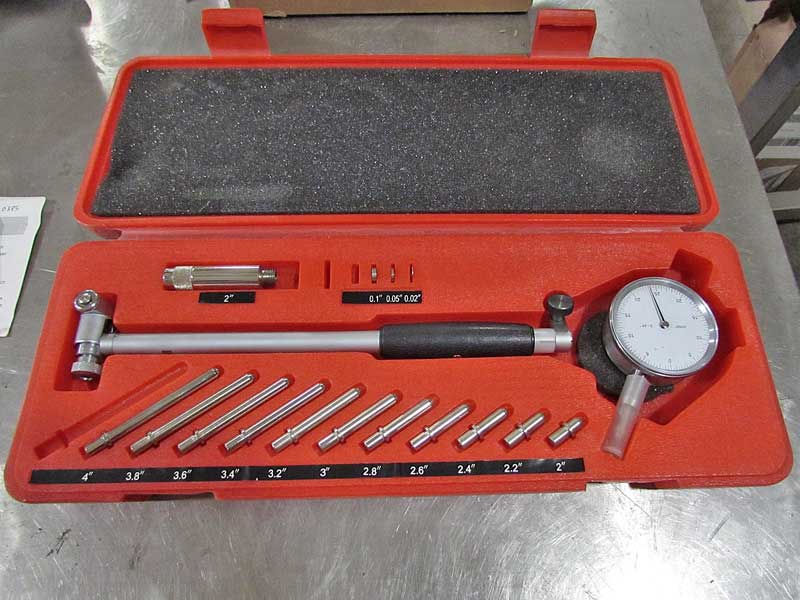
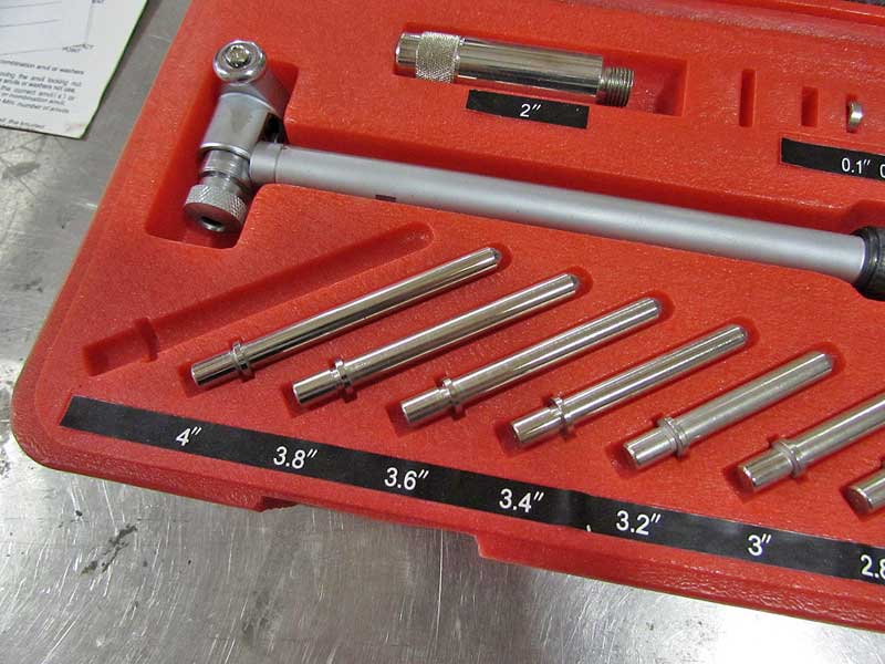
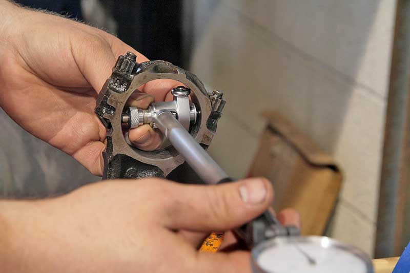
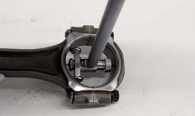
the lubed crank shaft will take a bit more effort to start it rotating than it takes to keep it rotating, as the surface tension and lube shear takes a bit of effort to get it rotating, thats one reason the torque beam style torque wrench is preferred too check the resistance , as you get to see both starting and rotational resistance on the wrench scale, rather than the click style torque wrenches design for verifying the rotational resistance, and be aware that the resistance should NOT significantly change as the crank shaft rotates through its full 360 degrees, if it does it may indicate a block that needs to be line honed to cure a slight block warp- age issue or a bent crankshaft, a dial indicator and an accurate bore gauge and a good solid stand for the indicator can help you locate the cause.
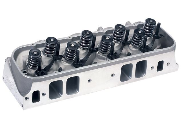
theres zero doubt you can build some of the more common SBC and BBC engines with either a mix of O.E.M. and and aftermarket components,
BE AWARE NOT ALL POTENTIAL PARTS COMBOS ARE COMPATIBLE
or go with just aftermarket components through out.. It should be obvious that you'll need to do some research , and calculations on,
rod length, bearing clearances, compression height, compression ratio, quench, and valve train geometry,intended port flow, valve lift,
and carefully verify the clearance , and valve train geometry issues before ordering components, and during the actually assembly.
https://www.amazon.com/dp/B06VXC1FPL/ref=nav_timeline_asin?_encoding=UTF8&psc=1
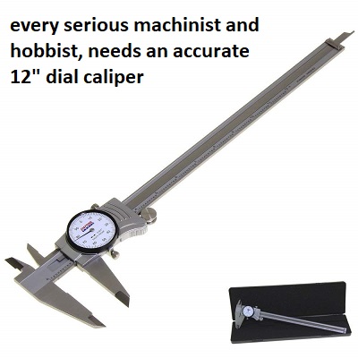
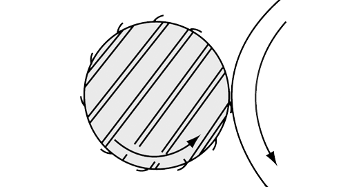
as to the rotational smoothness, be aware that, all assembly lubes and oil on blocks bore the rings ride over and all bearing surfaces, coated with oil and assembly lube provide a surface shear tension that must be broken before the crank turns,
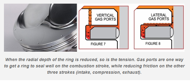
so its not un-usually for the rotating assembly after the pistons and rings are installed, too require lets say 35 ft lbs to get the assembly too start too spin ,but only 15-26 ft lbs to keep in rotating , (low tension rings provide less drag) you can generally call the piston ring manufacturers and they should know approximately what torque reading on the crank snout, a socket and a torque wrench will require to have the engine assembly rotate with their rings installed.
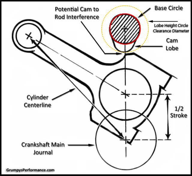
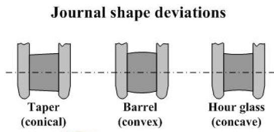
a crank snout, turning socket, but if that short block assembly, takes over 35-40 ft lbs too start it rotating, once its assembled without cylinder heads attached, you've got serious issues, like cam lobe to connecting roods hitting or a connecting rod facing the wrong way on the crank journal, or the wrong size bearings, or the crank journals not the right size, badly polished or not round
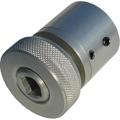
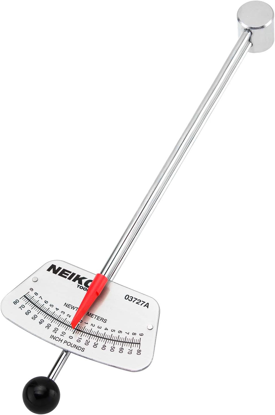
that's why you'll need a torque beam deflection torque wrench to check that
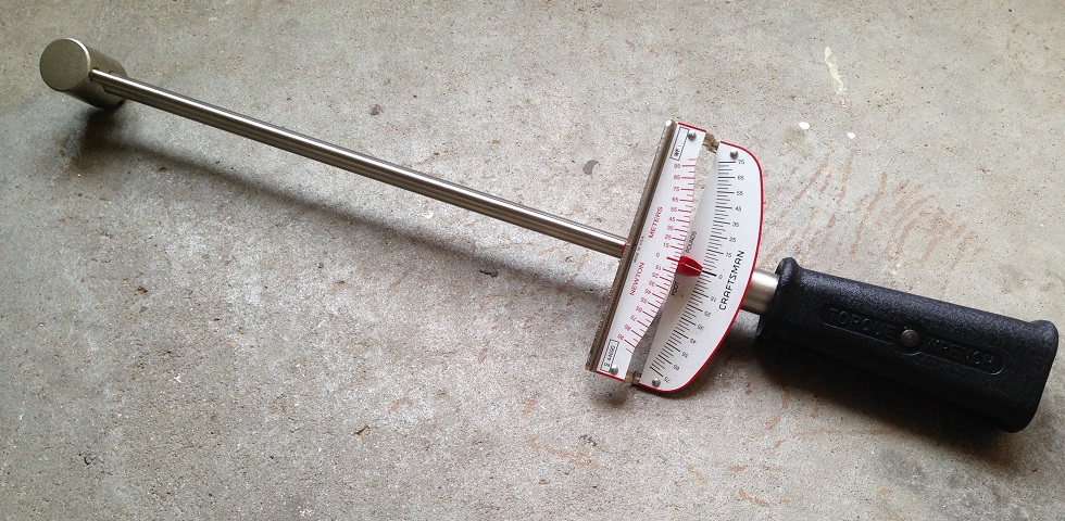
https://www.amazon.com/Presa-Drive-...ocphy=9012039&hvtargid=pla-669567243785&psc=1
read the labels and load rates carefully before ordering they make inch lb, ft lb versions
1/4",
3/8"
and 1/2"
drive versions
and having an inch lb rated one helps at times $25 on amazon
https://www.amazon.com/Neiko-03727A...ocphy=9012039&hvtargid=pla-572951906812&psc=1
https://www.ebay.com/itm/224242691491?epid=23014633155&_trkparms=ispr=1&hash=item3435e7eda3:g:sBkAAOSw5MFfuDZS&amdata=enc:AQAGAAACoPYe5NmHp%2B2JMhMi7yxGiTJkPrKr5t53CooMSQt2orsSvtkx670Z0mbyfWqmxLFLYbSgftsPKn4P4%2BuyGMgnhW%2FjIce0dpW9M3RoBZspmh1OP12%2B1VAxoUJJj3RoXfTi%2BdPDYwWVpZhnEHOtxRJrO9BgZbW7EgR6P7ToLFxxssR3y9JK0MrcC1gFkn3SW32QlRm1jVDvf75zsqK4K6a3ZYjn8qwXzUYq6h4garZZxJfbfur3C7bxYsXM6Kd0RP%2Bc1qcqgfVJHBlQgVk4udvEWA36jrjTVJl5%2BCY4o1Ivq4bl7iQqsi7Hf9CMDhs1uIRQNOVZaGYqWg9k4J0UBWdzz8l8X%2FOqd9t3DRpXca5J9mjp65pFUANhTN3TfDEtTpSfCkWmlHnqMmYCOvLSwvD1QZMXkSF0aOKRqnGjBtvV0xFal9s9EMVlX8gRTesUivsA%2FodQ%2FlEYPwFdqVXGP1WdDLW4J90gTGRKzasKw%2FOHt7XrubOgzy515noBgagP9s2M1iGfVGLK2dXotGyaTVcSbvCHNSmbSUvaKVX7Jm7hgX3UZIvrnEYFwbpAec4a0%2BqRPqov5SRFpkQ0DGE9tAvXszC8xwzF9%2F%2FxSK%2FPmvpoJ%2FxGmwoio1ZR88UMdq6GHkjzFQIpQE946bHSep0BzmPBPXyILyvAcxWgs1vPcytjTHBLwAMI0lLADbjgWGGJUMAl8nR2wLczSCeJC7Sd5lIfZ%2FPNxz8aB0qf73TtmocTHjhkcVWW3C0bmckieELPrUXPfLp6ltQmqHsGXDFoITaQRs0mPFQ4TRBoUyYcGtfrS8V8XHcQ0TZtCtqoni0tUGwbdHFKQGYpD%2FFFTpEYitoFjODdATrumb5yl7bb5fAiIRVou6oUBD75feDSqdDpB7G23g%3D%3D|ampid L_CLK|clp:2334524
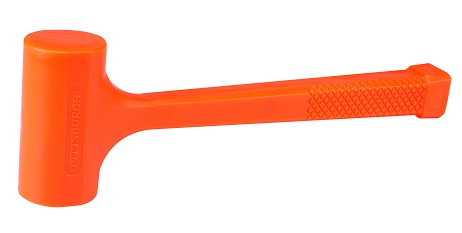
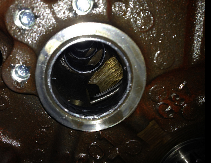
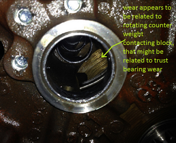
Don,t forget too use a large rubber, leather or plastic mallet, lead hammer to gently beat the crank seated in the bearings, both forward and aft in the block several times , too seat the thrust bearing,
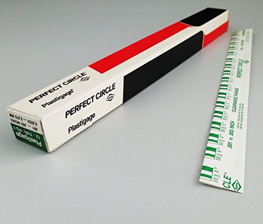
and of course use a dial indicator and plasti-gauge to verify clearances and too check clearances.
I'd alsp point out that all the main caps will need to be torqued in place in at least three stages to allow the block stress to disapate and equalize as the main caps are seated to the block and it helps to go back over the main cap bolts starting at the center and working outwards in a spiral as the caps are tightened at each torque stage.
YES READING LINKS WILL HELP A GREAT DEAL
http://garage.grumpysperformance.com/index.php?threads/thrust-bearing-wear.619/
http://garage.grumpysperformance.com/index.php?threads/precision-measuring-tools.1390/#post-68861
http://garage.grumpysperformance.com/index.php?threads/bearing-clearances.2726/
http://garage.grumpysperformance.co...ed-holes-in-bearings-shells.10750/#post-53298
http://garage.grumpysperformance.com/index.php?threads/precision-measuring-tools.1390/#post-44530
http://garage.grumpysperformance.com/index.php?threads/which-torque-wrench.342/#post-10864
SKIPPING READING THE LINKS IS GENERALLY GOING TO BE A MISTAKE
http://www.superchevy.com/how-to/engines-drivetrain/4380-bearing-clearance-info/
https://www.chevyhardcore.com/tech-...ies-measuring-and-setting-bearing-clearances/
https://www.chevydiy.com/pre-assembly-guide-build-chevy-small-block-engines/
http://knowhow.napaonline.com/know-notes-measure-engine-bearing-clearance/
https://www.mahle-aftermarket.com/media/local-media-north-america/pdfs-&-thumbnails/cl77-1-205r.pdf
http://www.superchevy.com/how-to/engines-drivetrain/0707ch-main-bearing-clearance/
https://www.enginebuildermag.com/2013/03/bearing-clearances/
https://blog.k1technologies.com/how-to-check-bearing-clearances
if your experiencing issues and the crank won,t rotate in the main journals very smoothly , STOP and find out WHY or take the block and crank to a trusted local machine shop, further assembly will just cause problems with long term durability if the basics are not correct! REMEMBER YOUR BLOCK MAY NEED TO BE LINE HONED OR THE CRANK MAY BE BENT OR OUT OF DIMENTIONAL SPECS,THIS NEEDS TO BE VERIFIED AND IF REQUIRED, CORRECTED
theres at least a few hours of very worth while , and quite useful reading in this thread and links that will prevent you wasting time and money, keep in mind the sub links contain a huge wealth of additional info youll need
what seems to be over-looked in many engine builds is simply the fact you'll almost always DEEPLY regret jumping into the engine build with both feet and waving your check book as you sink ever deeper into piles of parts receipts and machine shop bills, rather than stepping back with a legal pad, and a calculator and listing in minute detail exactly what you want to accomplish, and taking the time and effort too list and check out in detail what each machine shop procedure costs, why its required and how much each components costs, what your options are and how each component will add too or benefit the completed combo (or in some cases cause you time and grief)
stepping back and thinking things through in detail and listing the cost and potential problems and finding the solutions BEFORE you dive into the process may be a lot less fun, but in the long term its sure to cost less and result in a far better finished project!
you might be amazed at what a couple hours research into the subject will do to help you build a much more durable engine, and actually reading thru links and sub-links and asking questions helps a great deal
https://www.carshopinc.com/product_info.php/products_id/49347/SPG1-12
http://garage.grumpysperformance.co...ting-rod-tools-than-some-guys-may-want.16414/
http://garage.grumpysperformance.co...ting-resistance-to-look-for.11312/#post-51472
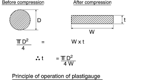
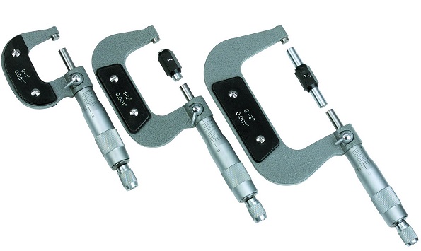
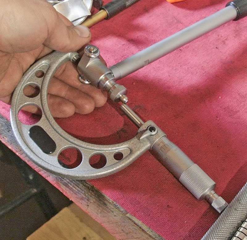
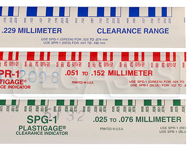
yes I use both micrometers and snap gauges and cross check with plasti-gauge
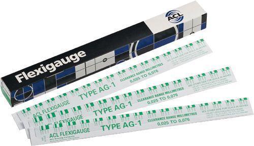
and yes when you compare the crushed width of the plasti-gauge youll find it rarely falls as an exact match to the bar chart tape that is packaged with it so you can judge clearance based on crush width
http://garage.grumpysperformance.com/index.php?threads/bearing-clearances.2726/
http://garage.grumpysperformance.co...piston-to-bore-clearance-on-your-block.14251/
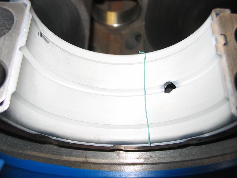
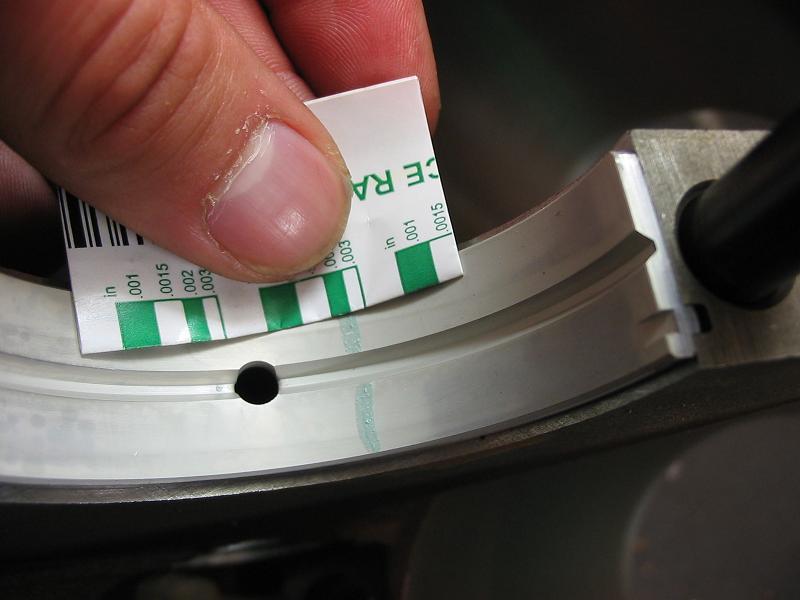
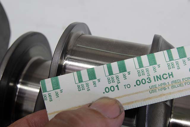
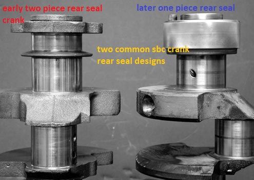
OBVIOUSLY YOULL NEED A TOOL TOO CHECK ROTATIONAL RESISTANCE,
sears sells them for about $20
home depot for $15
http://www.homedepot.com/p/Powerbui...e-Torque-Wrench-644044/203116749?N=5yc1vZc6ev
http://www.sears.com/craftsman-3-8-...999000&pla=&kispla=00932999000P&mktRedirect=y
http://garage.grumpysperformance.com/index.php?threads/bolts-a-bit-of-useful-info.4868/#post-13372
THIS BEAM STYLE TORQUE WRENCH IS THE TYPE TORQUE WRENCH YOU WANT TO CHECK ROTATIONAL RESISTANCE, these come in at least three torque ranges
for checking the rotational resistance you'll want the lower rated version, that reads 0-75 ft lbs or in inch lbs
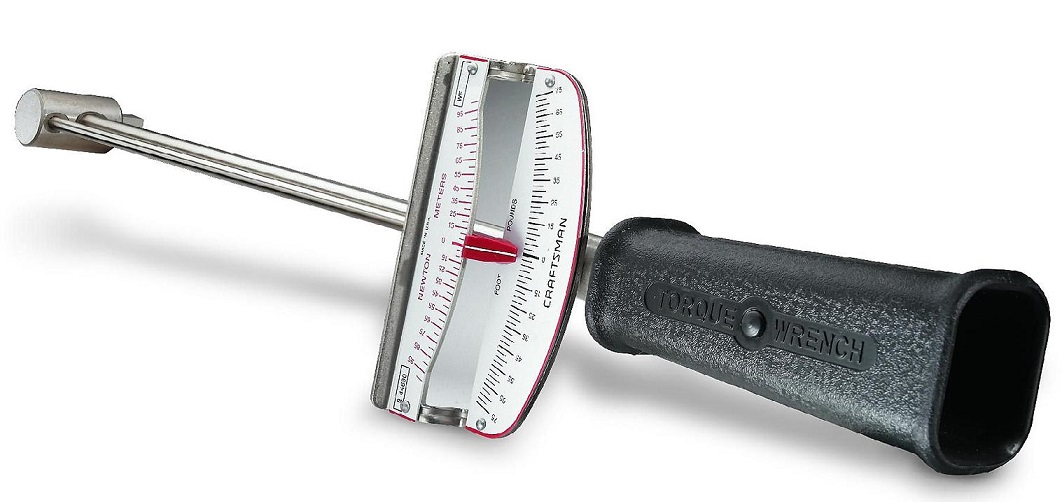
BUT NOT WHAT YOULL USE TO TIGHTEN HEAD BOLTS

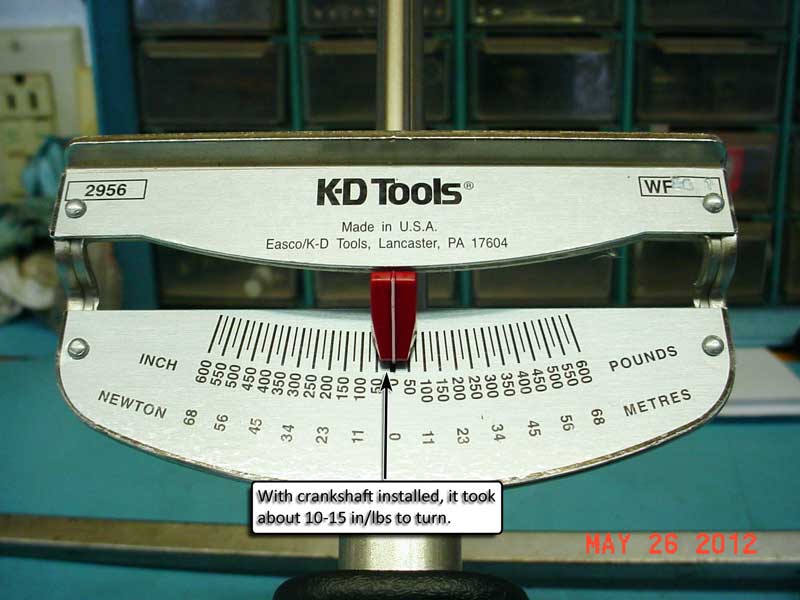
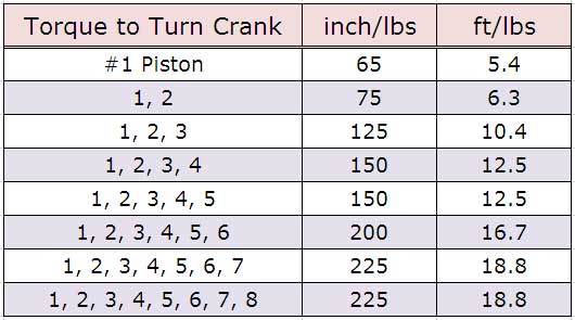
if your SBC engine requires over about 30 ft lbs to get it started rotating,
or over about 25 ft lbs to keep it rotating,
youve got issues that you need to look into before further assembly
use lots of moly assembly lube on the bearing surfaces
BBC will require about 3- 5 lbs more effort, on each point
(starting and keeping it rotating, once all 8 pistons are installed)
as the rings lap into the bores and bearings seat, the resistance should rather rapidly be reduced a few ft lbs.
BORES should be lightly oiled and bearings coated with assembly lube.
http://www.4secondsflat.com/Thrust_bearing_failures.html
http://garage.grumpysperformance.com/index.php?threads/thrust-bearing-wear.619/
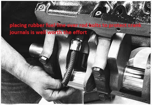
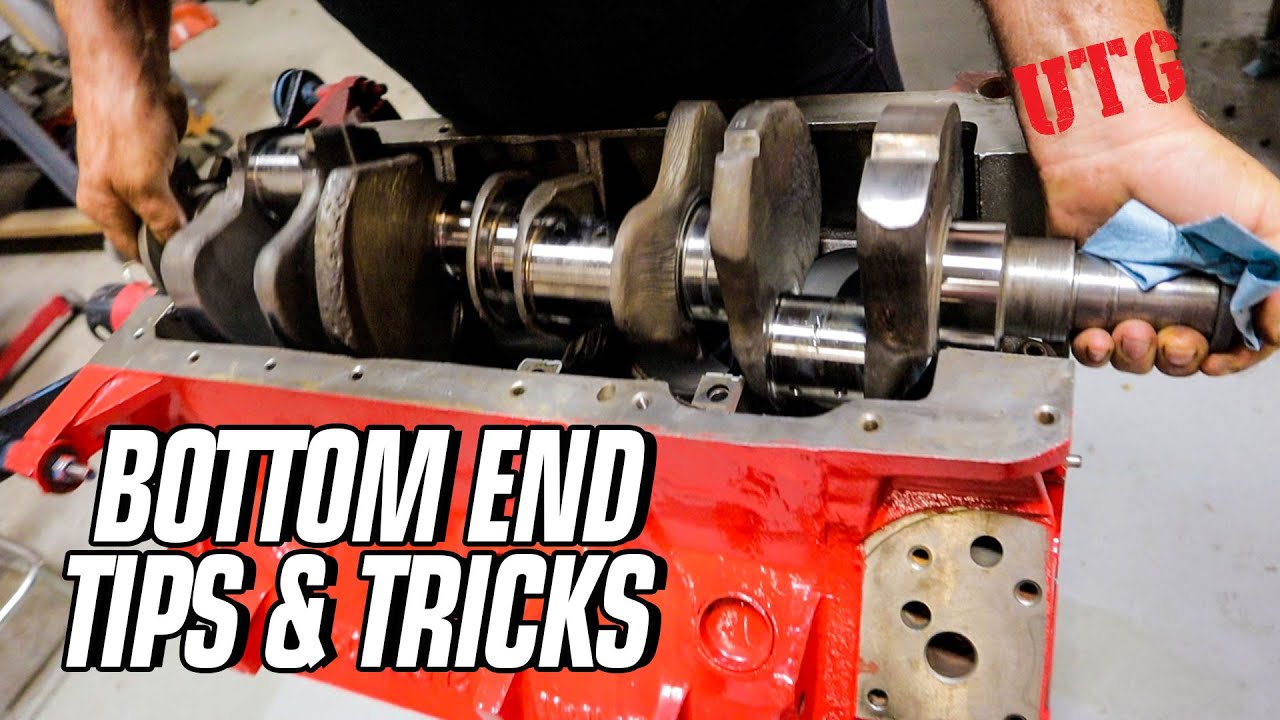
 www.youtube.com
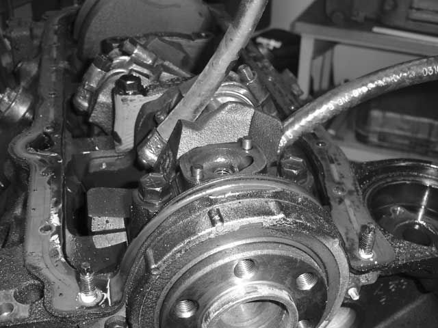
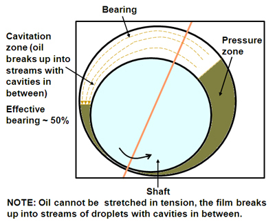
keep in mind the assembly lube or even oil on the bearing surfaces has a surface shear limit,
that why the crank is harder to start rotating but the required effort to keep it spinning is significantly lower,
your initial effort to twist the crank must break that surface tension on the lube,
once its sheared the lube forms a lubricating layer and metal to metal contact is prevented as the lube forms a barrier layer

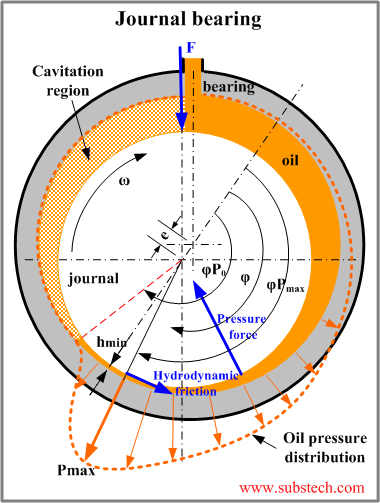
NEVER GUESS, DEAL IN PROVEN FACT!
Id get out the plasti-gauge and check clearances, don,t guess , know exactly what your dealing with!
if the clearance falls in spec and the bearings look decent they can be re-used, but its foolish to do so if they look overly dirty, worn or don't have the correct clearances
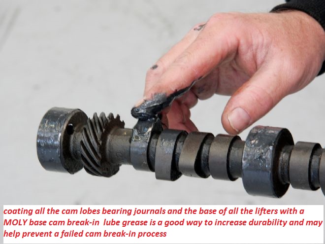
lots of moly assembly lube and spraying any potential moving contact surface with moly spray (like bearings ,lifters rockers) and liberal use of moly assembly lube during the break-in process helps reduce wear issues
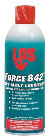
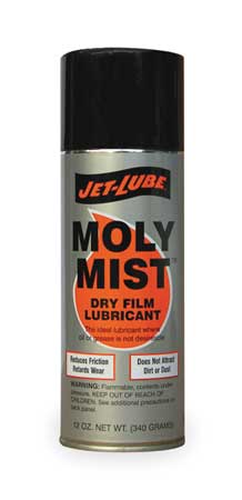
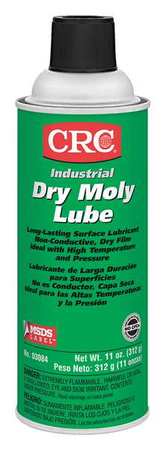
pre-spraying all bearing and valve train components with a moly based spray, helps embed micro moly lubricants in the metallic surface micro fissures , a good paste lube like cranes assembly lube over the spray surface helps insure a good lubricant surface coating, that is far stronger than just the ZINC and PHOSPHATES in oil
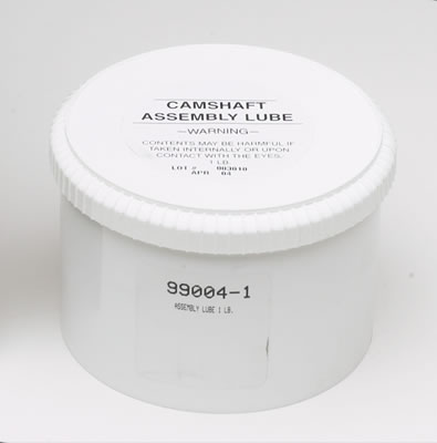
Take the effort and time too CAREFULLY.. read links and SUB LINKS,
THIS is almost mandatory on this web site!
if you want all available useful & related info
http://garage.grumpysperformance.co...earances-and-journal-surface.9955/#post-38385
http://garage.grumpysperformance.com/index.php?threads/bearing-clearances.2726/#post-26440
http://garage.grumpysperformance.co...hrust-bearing-failure-info-related-info.1138/
http://garage.grumpysperformance.co...ing-parts-and-a-logical-plan.7722/#post-72126
http://garage.grumpysperformance.com/index.php?threads/can-you-reuse-bearings.5544/
http://garage.grumpysperformance.com/index.php?threads/bearing-clearances.2726/#post-7077
http://garage.grumpysperformance.co...shaft-journal-surface-finnish.2728/#post-7079
https://www.mahle-aftermarket.com/m...b-2-1114-engine-bearing-failures-brochure.pdf
http://garage.grumpysperformance.com/index.php?threads/precision-measuring-tools.1390/#post-68194
http://garage.grumpysperformance.com/index.php?threads/causes-of-bearing-failure.2727/#post-13056
http://garage.grumpysperformance.com/index.php?threads/don-t-beat-that-damper.83/#post-14101
http://garage.grumpysperformance.com/index.php?threads/thrust-bearing-wear.619/#post-10925
http://garage.grumpysperformance.co...tion-of-crank-durring-short-blk-assembly.852/
http://garage.grumpysperformance.com/index.php?threads/assembly-lube-summary.6352/#post-68508
http://garage.grumpysperformance.co...ear-articles-you-need-to-read.282/#post-57371
I generally use CLEVITE (H) bearings as they have a bit more edge to crank journal edge radias clearance for the bearing shell to crank counter weight clearances
With the crank shaft alone in the main bearings, any inconsistency in the assembly lube thickness, or journal surface finish could and probably will cause a difference in rotational resistance or drag, if it spins fairly easily with a couple fingers on the crank snout with all the mains torqued down and your plastic-gauge checks and micrometers say the bearing clearances are correct your going to be fine, I generally look to have less than 5 ft lbs resistance , on keeping it rotating, once it starts to move, a properly installed strait crank in a properly honed set of main caps with properly clearances main cap bearings well coated with a 50%/50% mix of assembly lube and marvel mystery oil on the bearing crank surfaces and less than 10 lbs to get it to start rotating as the surface tension of most assembly lubes will resist rotation until it starts to rotate, then the resistance to rotation drops off rapidly,
on a newly rebuilt engine the SHORT BLOCK (no heads installed) and with the bearings and cylinder bores oil coated, it should require LESS than 40ft lbs to get rotating and less to keep it rotating, a crank ALONE installed in the correctly tightened main caps should require LESS than 10 lbs to start rotating and far less to keep spinning.
a used engine will develop a bit looser clearances and require LESS force to rotate after the heads are removed.
on a racing engine the crank alone can easily be spun in the main bearings with your fingers and over about 25-28 lbs resistance when using low drag rings usually indicates a problem
a used engine will develop a bit looser clearances and require LESS force to rotate after the heads are removed.
yes having an accurate torque wrench is mandatory when you build an engine, yes having the piston to bore clearance, ring end gap and bearing clearances correct helps a great deal, and yes low tension rings DO tend to reduce the resistance to rotation, and yes, some assembly lubes DO make the engine a bit harder to start the rotation.
obviously a slightly bent crank, inconsistent bearing clearances, non-round crank journals , rough polish surfaces on journals or a block that needs to be line honed or a bent cam or tight cam bearing journals or improper bearing clearance or dry bearing surfaces tend to increase resistance.
IF your engine resists rotation to a higher torque load rate
FIND OUT WHATS BINDING BEFORE PROCEEDING FURTHER, you sure won,t be the first guy to have installed something incorrectly or had the wrong clearance's but catch it BEFORE proceeding further
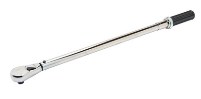
HUSKY $88 (worked rather well, over all I was pleased)
http://www.homedepot.com/p/Husky-1-2-in-Click-Torque-Wrench-H2DTW/202916180?N=5yc1vZc6ev
CONNECTING ROD SIDE CLEARANCE AND THRUST BEARING CLEARANCES MUST BE CORRECT.
CONNECTING RODS AND PISTONS MUST FACE THE CORRECT DIRECTION AND RING END GAPS MUST BE CORRECT AS WELL AS BEARING CLEARANCES, and THE OIL PUMP MOUNT STUD MUST NOT TOUCH THE REAR MAIN BEARING SHELL
now once you add all the connecting rods, pistons and rings obviously resistance to rotation will increase as rings slide along bore walls and you've added rod bearings, Keeping in mind that we are discussing a short block with no heads installed yet and rings riding on well oiled cylinder walls, that should require less than 40 ft lbs to spin, less than 30 lbs of resistance is ideal, because an engine turns more easily with the heads removed or the spark plugs removed.
a crank bye it self ,sitting in a properly machined block with the bearings in place, having been coated with a decent assembly lube, (I generally mix CRANE CAMS ASSEMBLY LUBE WITH MARVEL MYSTERY OIL IN ABOUT A 50%/50% mix on bearings) and the main caps torqued in place should require no more that 10 ft lbs to start to spin (MAXIMUM) and in most cases noticeably less to keep it spinning, in-fact most are easily spun with finger pressure alone.
if it takes more than 10 ft lbs somethings either not machined correctly or your clearances or lube are wrong.
after you add the rods and pistons with the rings its resistance to rotation obviously increases but should still be UNDER 40 ft lbs to spin an assembled short block,If your carefully checking clearances you should see a minimal increase in resistance to the crank rotation, during assembly, as each piston assembly is added and torqued into place as ring drag increases resistance but the bearings should add little or any drag if properly sized and lubed.
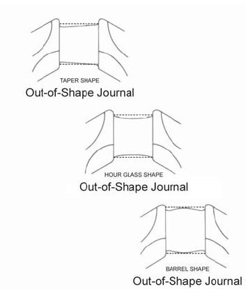
obviously youll want to check the piston to bore clearance at several locations along the circumference of the bore to piston clearance, and check the blocks cylinder bore for consistent diam. and the bore being truly round in shape and but don,t forget to check the piston ring groove back clearance in the ring grooves and the ring end gaps plus look for piston pin bind in the piston pin bore, look for rod journals that are tapered or out of round and connecting rods with a big end thats not round or bearing that are not consistent in diameter across the bearing bore, but Ive also occasionally seen guys try to install rods without checking side clearance or who failed to get the correct side of the connecting rods facing each other or guys using rod bearings that didn,t have the correct edge bevel to clear the journal s radias edge, usually the narrower clevite (H) series have extra clearance
Get out the torque wrench and with the damper bolt installed turn the crank,and while its yet to have the rods and pistons installed, and its lying in its bearings, IT SHOULD TAKE ABOUT 10-12 ft lbs OR LESS to get it moving, and LESS than 10 lbs to keep it moving.
EVEN IN NEW MAIN BEARINGS, it should REQUIRE EVEN LESS ONCE IT LAPS INTO PLACE WITH THE ASSEMBLY LUBE
IF it takes more force theres a clearance issue or the crank or block needs to be checked carefully for straightness, journal tapper and roundness and surface finish and the bearings need to be checked for clearance and proper installation and crush,remember if it won,t turn or spin easily STOP RIGHT THERE and find out why! don,t forget to check the TRUST BEARING fore and aft movement/CLEARANCE
once youve installed EACH connecting rod, you'll want to do the test again, remember each piston with its rings adds drag, AND YOU NEED TO VERIFY THE RING GAPS AND PISTON GROVE DEPTH AND CLEARANCE TO ALLOW THE RINGS TO SLIDE BACK INTO THE GROOVES, but in a well oiled cylinder,its not going to add a huge increase, in drag, as the rings ride on an oil film that prevents incorrect full surface physical contact, between the ring face and bore walls, and the bore surface will lap into the rings and vice versa during the break-in process.
IVE dunked my piston/ring assembly's in a can of MARVEL MYSTERY OIL just before installation with a ring compressor and have never seen the slightest indication of problems either on ring sealing getting the rings broken in, or on tearing the engines down later for inspections the amounts not that great, ideally each one installed adds a bit of resistance but at no time should the short block take over 40 ft lbs ABSOLUTE MAXIMUM to start it spinning,and LESS than 20 lbs to keep it moving, even with all the rings and pistons installed,yes you need to verify the bearing clearances during assembly and IT SHOULD take between 20lbs-25 lbs to start it spinning if the clearances are correct! and LESS than 20 lbs to keep it moving
IF it takes over 40 ft lbs to get it rotating ,youll need too DISASSEMBLE and FIND OUT WHY!
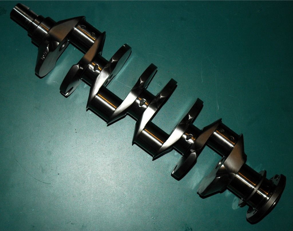
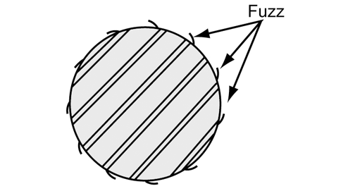
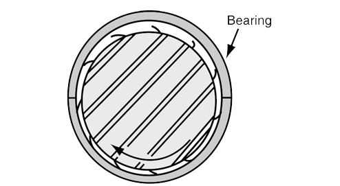
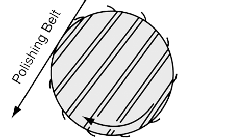
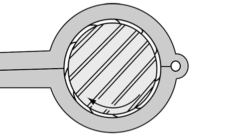
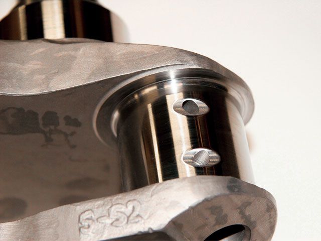
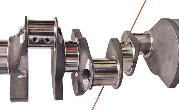
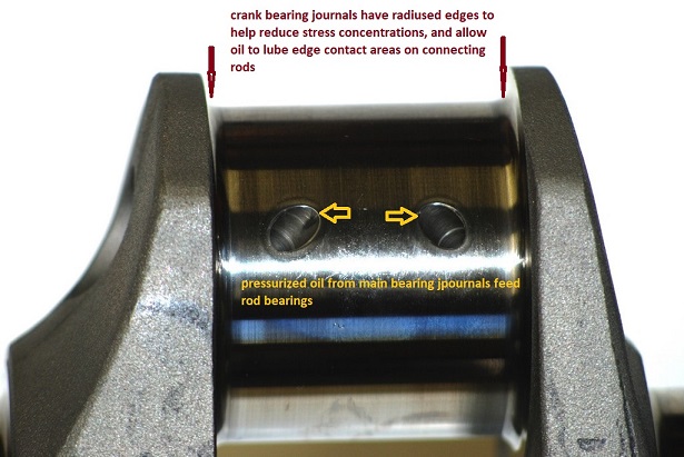
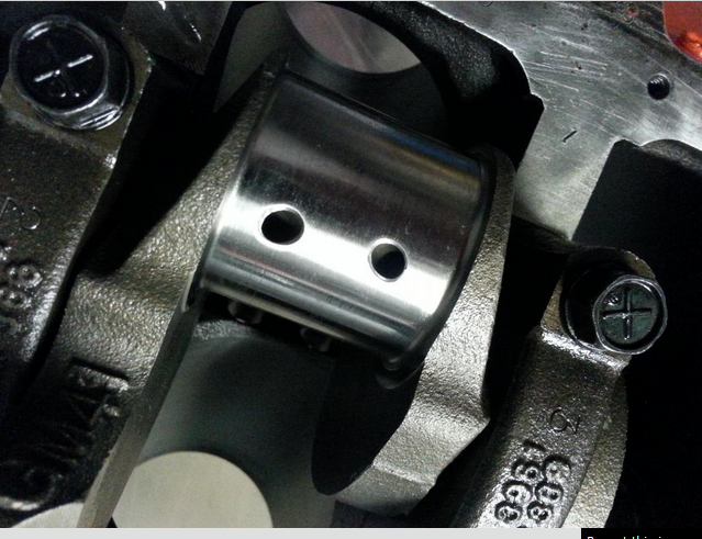
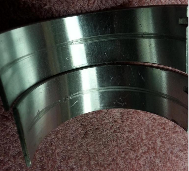
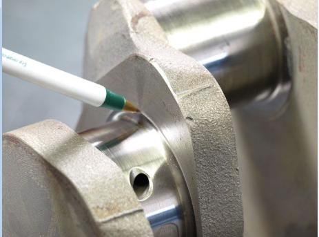
when you get the crank polished take the time and effort to clean out any cross drill oil feed passages and to very carefully de-burr the passage opening edges, as this is a very commonly overlooked issue, below is what at first looks like a perfectly polished crank, with oil feed passages to the rod bearings, but the deep scratches the oil feed passage openings left in the rod bearing surfaces bare witness, after a single rotation, during a trial assembly show they are HARDLY burr free or ready for use, and obviously he failed to check each rod bearing during the assembly process, and probably ignored , what was very likely un-even or rather excessive resistance to the crank rotation. which should never exceed about 40 ft lbs even with all 8 rod bearings and pistons installed
http://garage.grumpysperformance.com/index.php?threads/precision-measuring-tools.1390/
http://garage.grumpysperformance.co...n-my-3rd-rear-main-seal-bbc.11084/#post-49384
http://garage.grumpysperformance.com/index.php?threads/replacing-a-gen1-rear-main-seal.474/#post-585
http://garage.grumpysperformance.co...gine-project-dart-shp.3814/page-12#post-17457
http://garage.grumpysperformance.co...od-rod-length-too-stroke-info.510/#post-10311
READ THIS LINKED INFO
Common assembly clearances
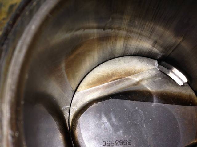
GET THE RING END GAP TOO TIGHT AND WHEN THE RINGS EXPAND WITH ENGINE HEAT THE ENDS TOUCH THE RINGS LOCK IN THE BORE AND THE PISTON LANDS SHEAR OFFGET THE GAP A BIT TOO LARGE AND YOU MIGHT BURN A BIT MORE OIL OR LOOSE SOME COMPRESSION, YOU'LL SEE A CHART LATER IN THE THREAD, BUT GENERALLY YOU'LL WANT .0045-.0065 PER INCH OF BORE DIAM. FOR A RING END GAP
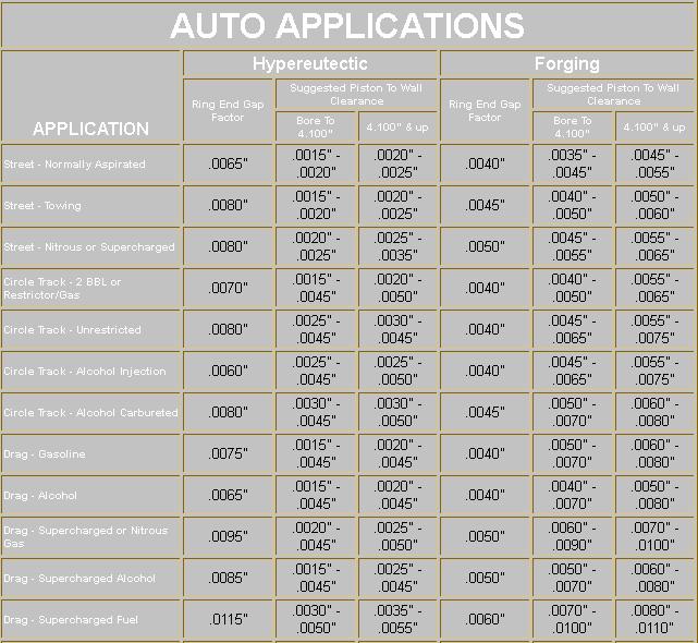
(ALWAYS consult your piston manufacturer for recommended clearances. Many pistons require a tighter bore)
Piston to bore 0.0055 - 0.0065" ( measured at centerline of wrist pin, perpendicular to pin)
Piston ring gap MINIMUM end clearances Top 0.022"
2nd 0.016"
Oil 0.016"
Wrist pin 0.0006 - 0.0008" in piston, 0.0008 - 0.0010" in rod for full floating pin (End play 0.0 - 0.005"
Rod bearings 0.002 - 0.025" , side clearance 0.010 - 0.020"
Main bearings 0.002 - 0.003" , 0.005 - 0.007 crankshaft end play
Piston to head clearance 0.035 MINIMUM including gasket (steel rods), 0.060" MINIMUM aluminum rods
Valve to piston clearance MINIMUM 0.020" exhaust , 0.010" intake NO VALVE FLOAT
Recommended: 0.080 intake, 0.100 Exhaust (steel rods) 0.100 intake, 0.120 Exhaust aluminum rods
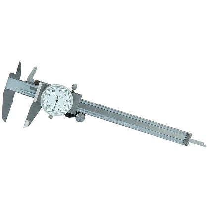
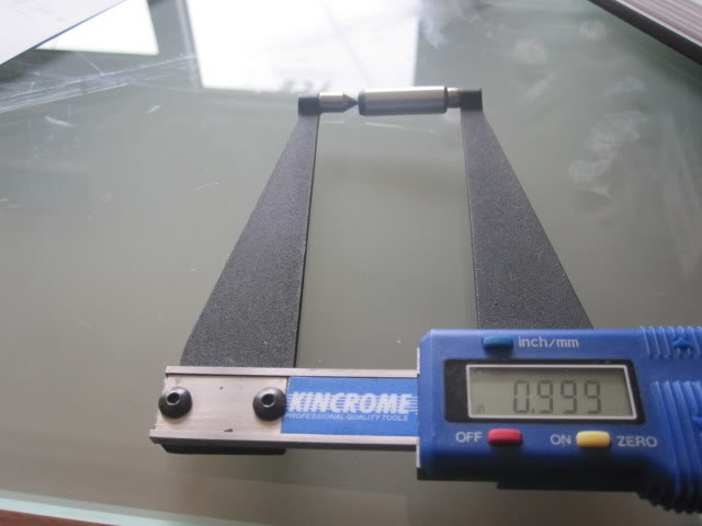
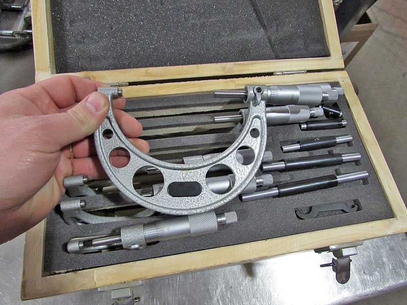
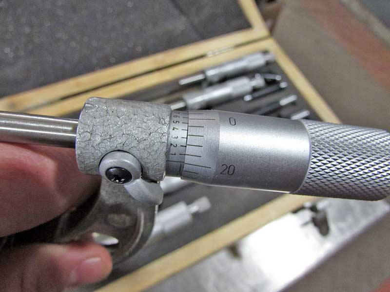
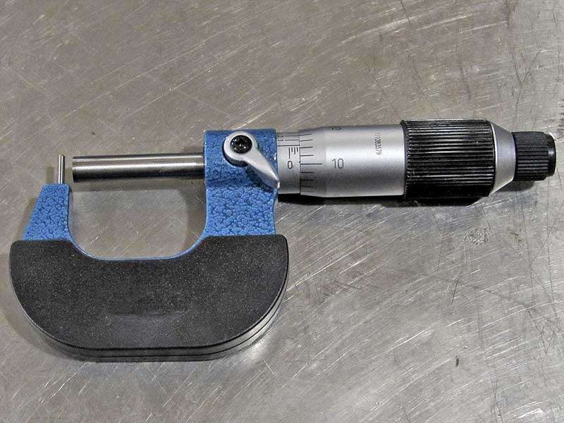
Ive got a full set of Mitutoyo mics 1" 2" 3" 4" 5" I paid several hundred dollars for,
and a cheap duplicate set from northern tool mics along with half a dozen different digital calipers and so far they all are consistent enough that theres not been any effective difference.
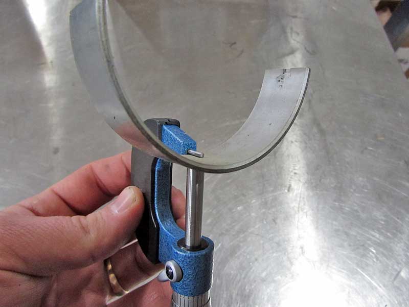
now I fully agree theres a very noticeable difference in quality , that's not debatable,if you need to know that last couple ten thousands of an inch your wasting any money spent at HF MICROMETERS , the accuracy is just not available but if your just measuring something like a piston ring thickness, or crank journal diam. and getting within 2 ten thousands plus or minus is ok, they all work well enough, and for most hobby level builders I think thats true! especially when I see guys installing rings right out of the box without checking end gaps, or even using plasti-gauge to check bearing clearances
and yes I constantly cross check them against each other, in fact I generally use several mics and a digital caliper during engine assembly, and constantly recheck against the precision gauge blocks and feeler gauges
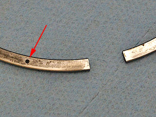
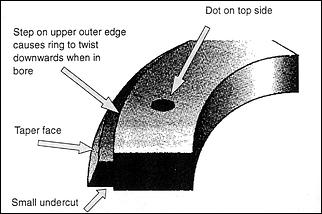
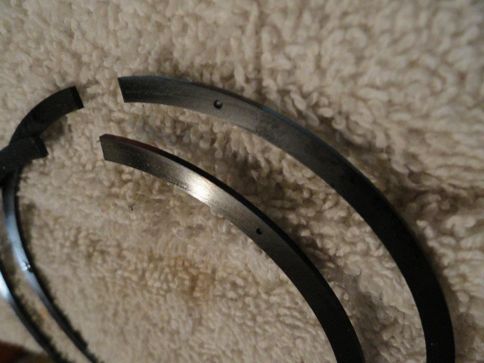
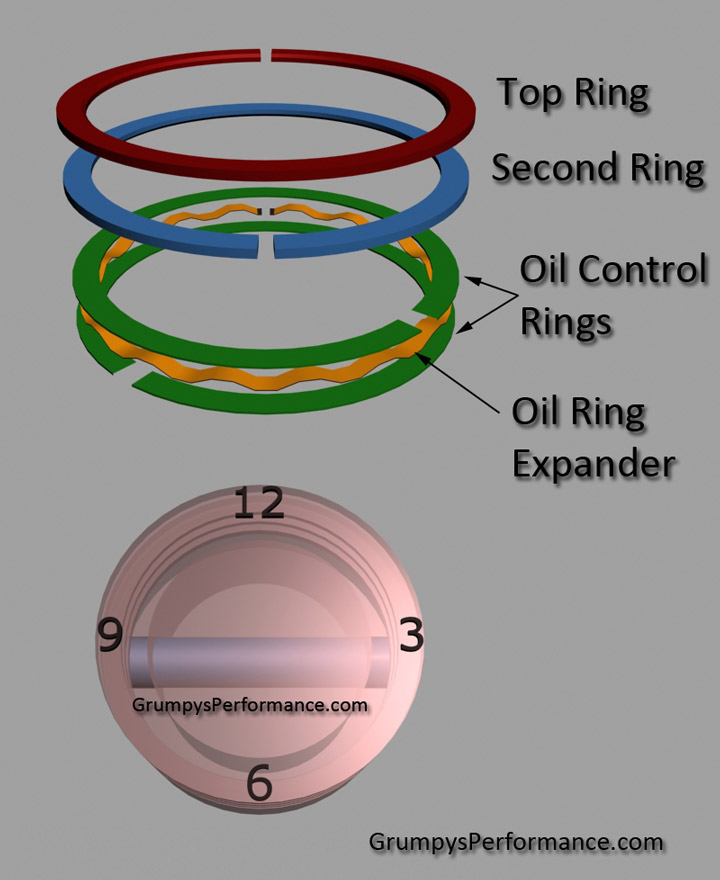
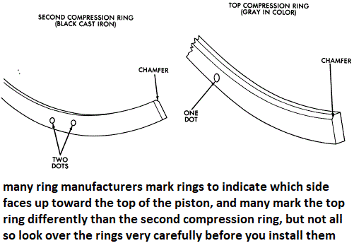
most piston compression rings have a dot on the upper surface to indicate the side designed to face the top of the piston
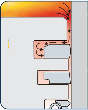
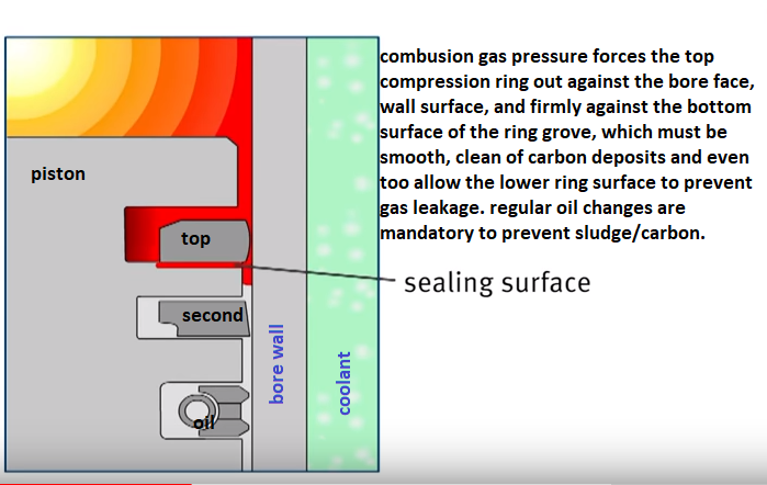
ideally the pressure above the piston gets behind the top compression ring and increases the force holding the ring face to the bore surface, noticeably more than the ring tension alone can do.
http://www.enginelabs.com/engine-tech/e ... ng-tension
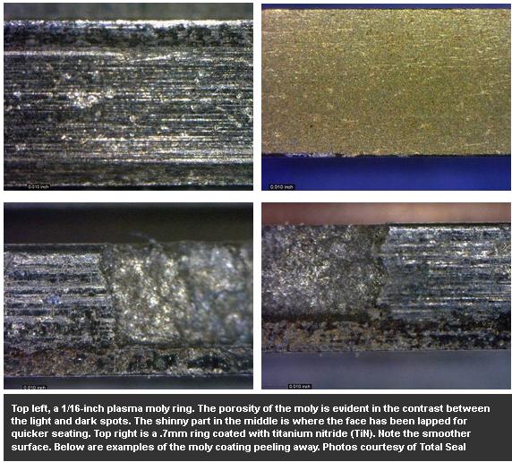
If you put together a stock 400 Chevy, and put standard tension rings in it, it’s probably going to take about 30 to 35 foot-pounds of torque to turn that shortblock,” Massingill said. “If you put it together with the rings that we utilize [for the Engine Masters Competition], it’s going to take about eight or nine pounds. Can you imagine, at 7,000 or 8,000 rpm, the difference that that is? It can easily be 30-35 horsepower.”
BTW
IVE dunked my piston/ring assembly's in a can of MARVEL MYSTERY OIL just before installation with a ring compressor and have never seen the slightest indication of problems either on ring sealing getting the rings broken in, or on tearing the engines down later for inspections
remember that when you go to re-install the compressed piston rings, and piston in the engine block,bores that dunking the piston in MARVEL MYSTERY OIL , just before, its slid into the ring compressor will coat the rings and bore contact areas enough to prevent many small problems that insufficient lube might case
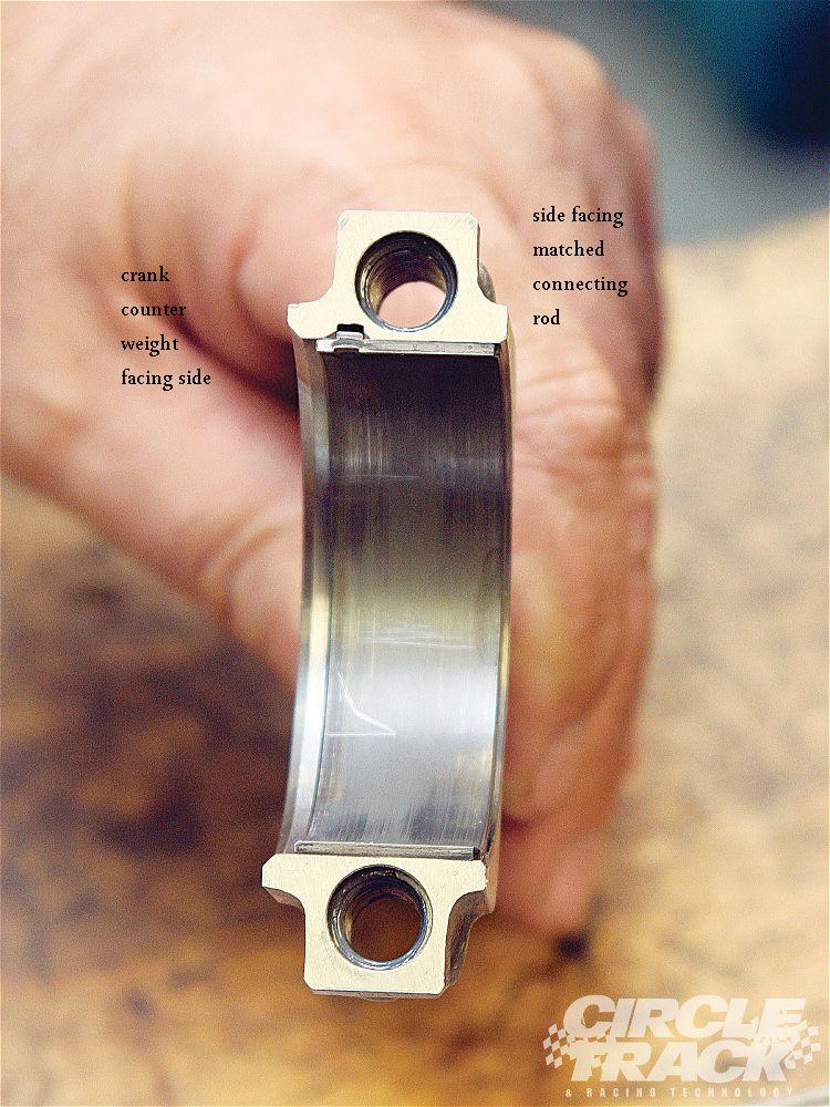
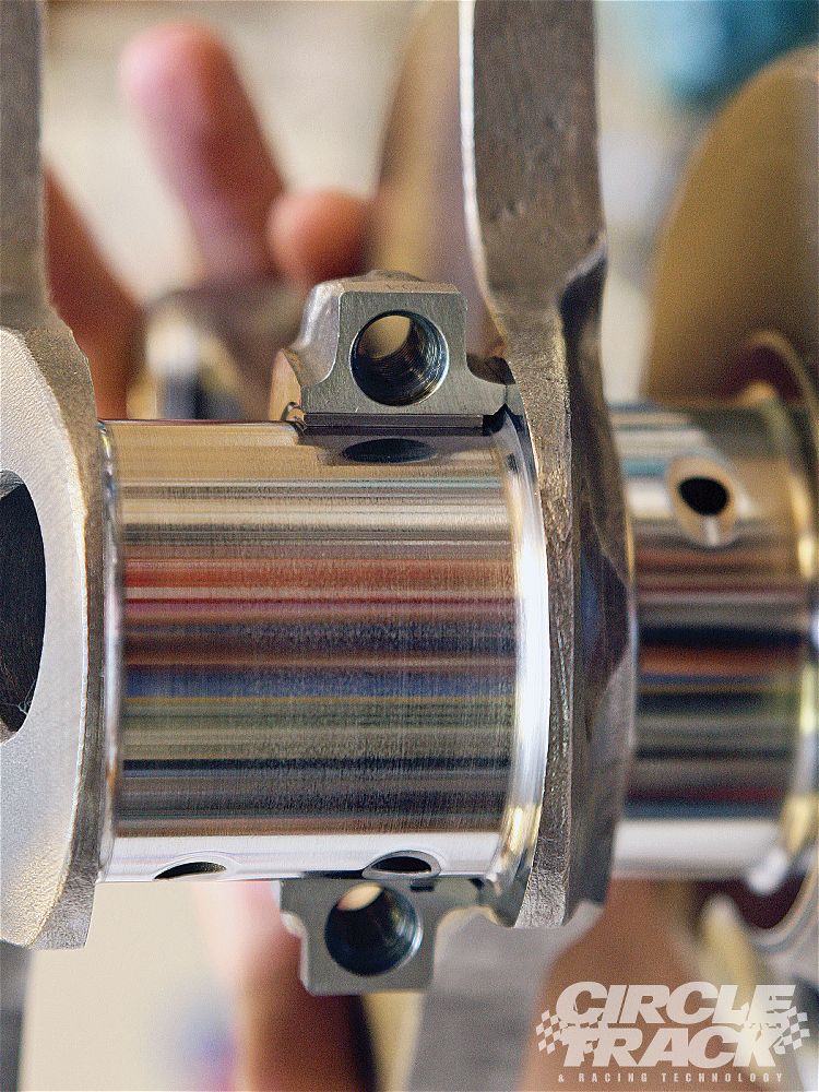
bearings AND connecting rods have an inner facing side and outer side the inner side facing the matching rod has far less edge clearance because they don,t need the radias that is required for the edge of the crank journals
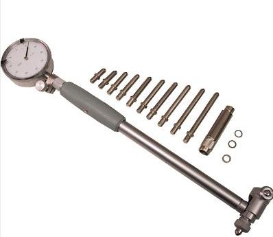
https://www.youtube.com/watch?v=8GVQiYAVSDQ
btw
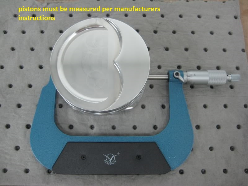
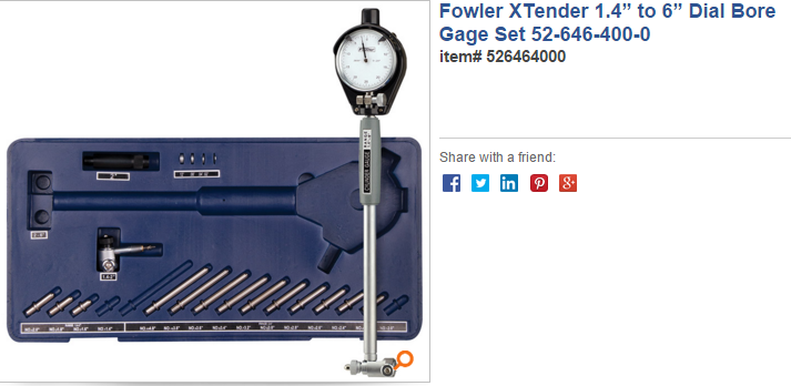
http://www.tooltopia.com/fowler-72-646-300.aspx
https://www.youtube.com/watch?v=LcOHsZxuqAM&t=23s
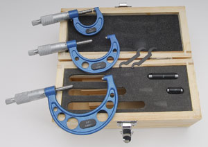
heres the good assembly lube (I usually add about 10% oil too the assembly lube,to get it easy to smear on surfaces during the assembly process)
http://www.cranecams.com/index.php?show ... l=2&prt=15
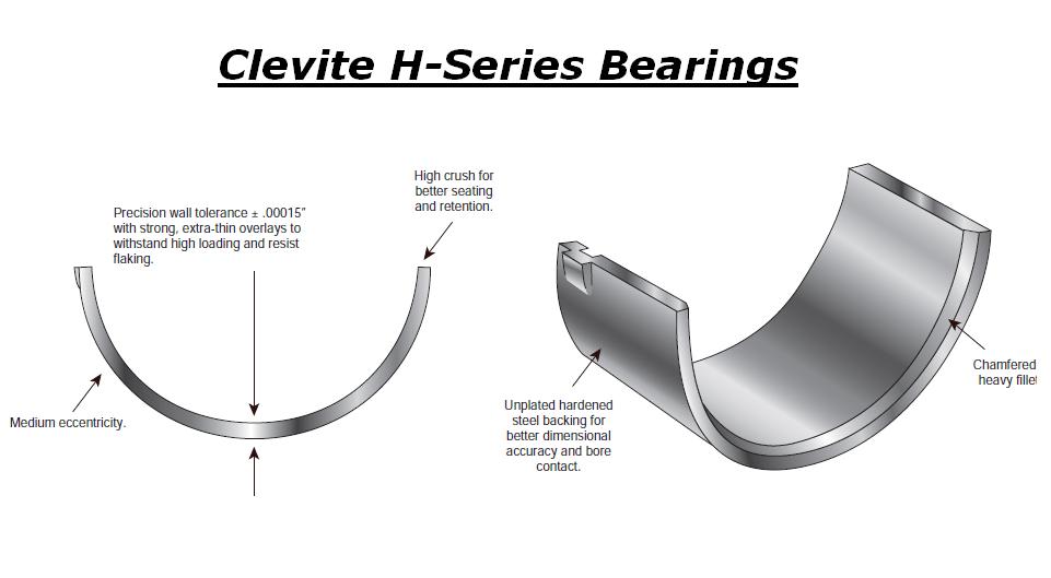
Ive generally found the H-series bearings are the best choice
MORE USEFUL INFO
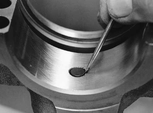
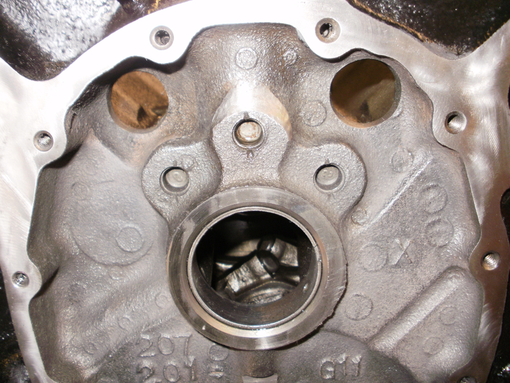
BE 100% SURE that the oil pump bolt or STUD doesn,t protrude past the inner main cap surface , because if it bears on the rear main bearing shell it will almost always result in a quickly failed rear bearing
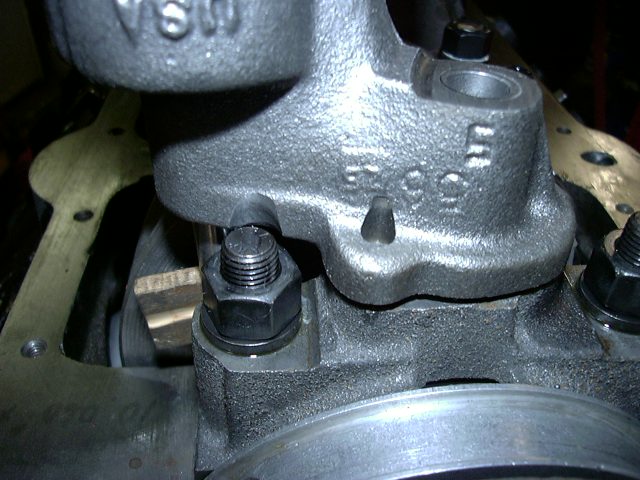
failure to use the correct stud, bolt or nut,
OR OIL PUMP FOR THE APPLICATION,
or check clearances when mounting an oil pump,
can cause problems
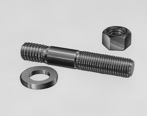
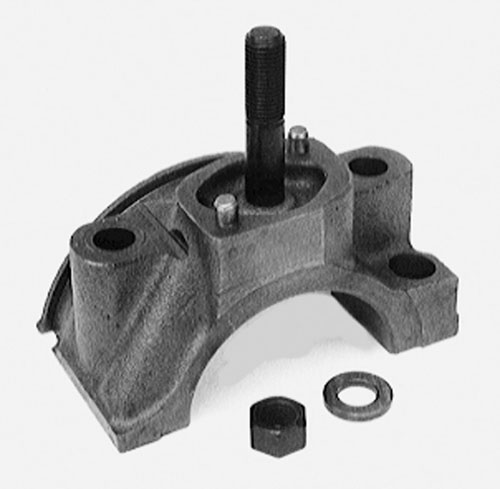
ONE RATHER COMMON MISTAKE IS USING THE WRONG OIL PUMP STUD OR BOLT TO MOUNT THE OIL PUMP AS IF EITHER EXTENDS THRU THE REAR MAIN CAP IT CAN AND WILL BIND ON THE BEARING AND LOCK OR RESTRICT, SMOOTH ROTATION
http://engineparts.com/techbulletins/CL77-1-205R.pdf
viewtopic.php?f=50&t=1222
http://garage.grumpysperformance.com/index.php?threads/number-stamp-sets.1738/
http://www.chevyhiperformance.com/tech/ ... index.html
http://www.4secondsflat.com/Thrust_bear ... lures.html
http://www.circletrack.com/techarticles ... index.html
http://garage.grumpysperformance.com/index.php?threads/crankshaft-journal-surface-finnish.2728/
http://www.connectingrods.net/connectin ... tretch.php
http://www.circletrack.com/techarticles ... index.html
http://www.circletrack.com/enginetech/1 ... education/
http://engineparts.com/it_bearinginstall.asp
http://www.circletrack.com/enginetech/c ... ce_basics/
http://engineparts.com/it_crankinstall.asp
http://www.chevyhiperformance.com/tech/ ... index.html
the CRANE assembly lube is excellent but IVE used this grease mixed with a bit of mobile 1 oil as a substitute on bearings at times with excellent results
advance auto carries some
http://www.grumpysperformance.com/p1171 ... _large.jpg
http://shop.advanceautoparts.com/productdetail.aspx?MfrCode=VLV&MfrPartNumber=632&CategoryCode=3251
if your well lubed short block won,t spin at under 40 ft lbs once assembled even with high drag rings its a HUGE PROBLEM!
you need to use moly assembly lube
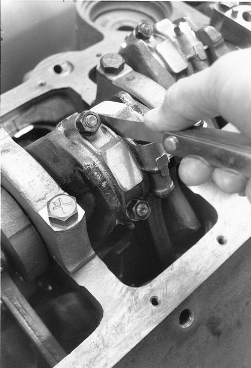
pull ALL the pistons and rods and verify the crank alone takes LESS than 15 lbs to spin, if not start checking clearances, once that's done verify the piston side clearances, then ring end gaps, ring to groove clearances in the pistons and the piston pin to piston pin bore side clearances,then remember the rods have an inner and outer facing side, and the bearings do also in most cases, check rod side clearance and thrust bearing clearance, and when your assembling the pistons & rods to the crank rotate the crank after each ones installed to find any unusual increased drag, a slightly bent rod, or the wrong bearings can add a good deal of drag
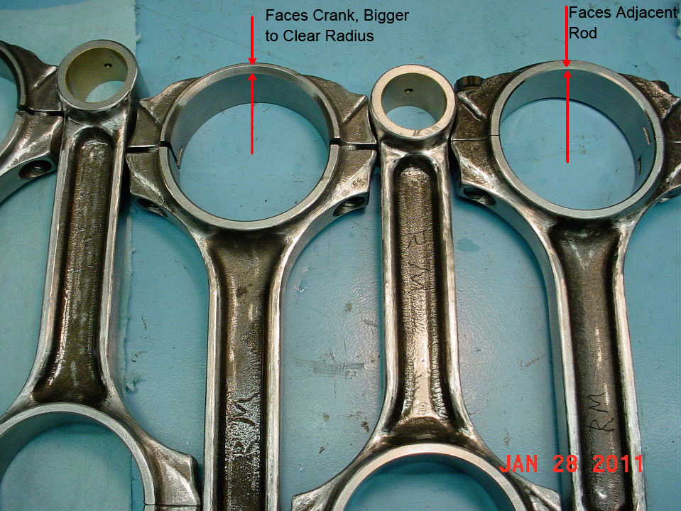
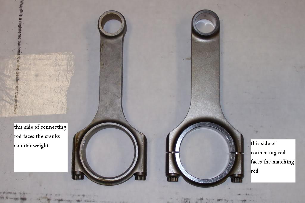
one factor to keep in mind is that rods typically have a side that rides against its matched companion and a side thats BEVELED for clearance on the crank journals radias EXAMPLE
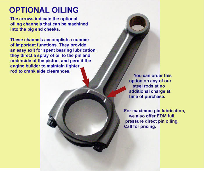
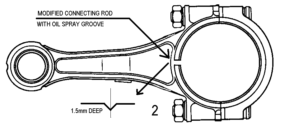
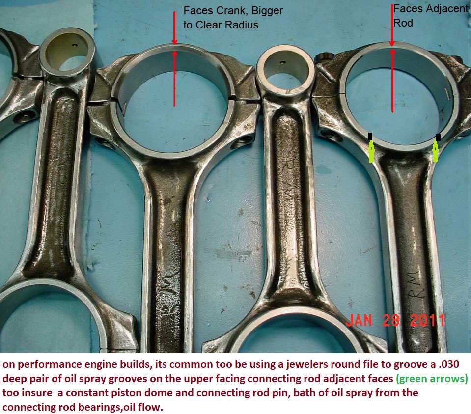
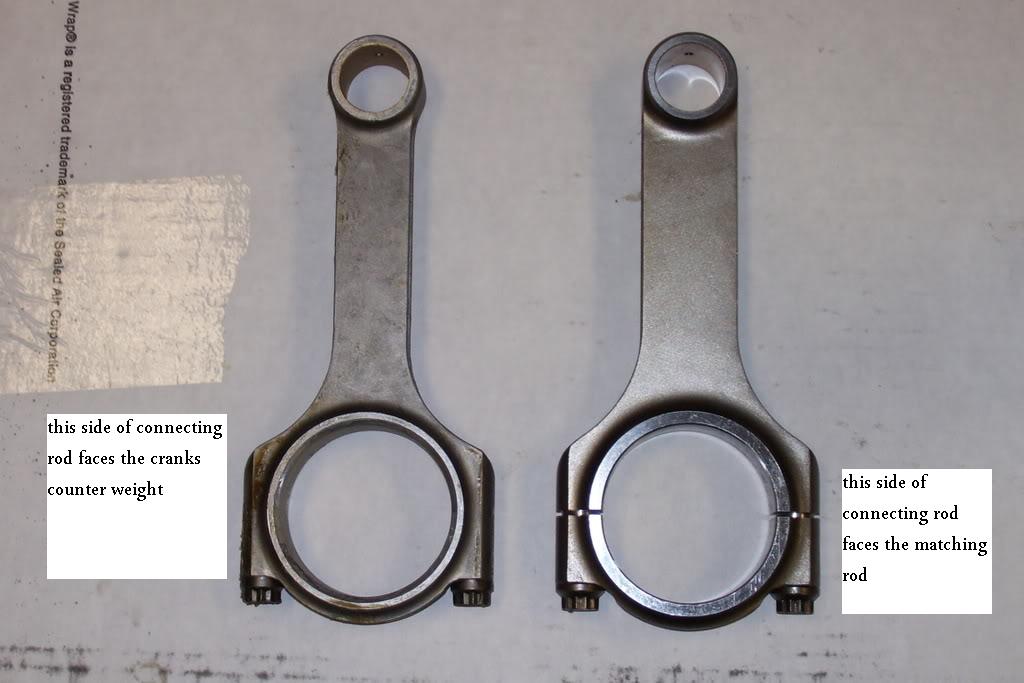
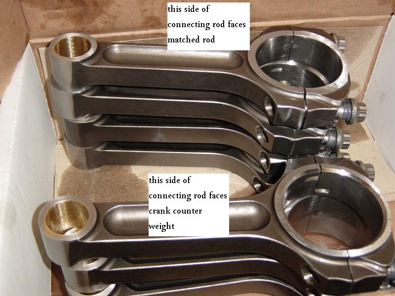
notice the top rods non-beveled side that faces the matching rod is up, but on the lower rod the the beveled side that faces the crank counter weight is up on the lower rod
notice how one side of the bearing holding section has a radias (left)(GOES TOWARD CRANK COUNTER WEIGHT) but the opposite sides flush (right) (FACES MATCHED ROD)
you really need to read thru these threads
http://www.circletrack.com/howto/1818/index.html
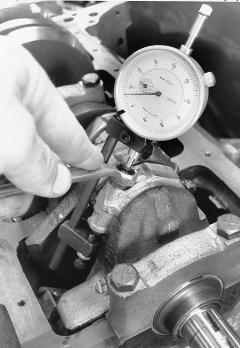
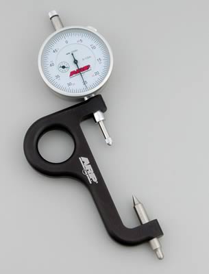
btw spray the bearing and the crank surfaces, and the plastigage with WD40 before you measure clearances and it won,t tend to stick as much
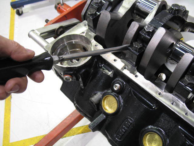
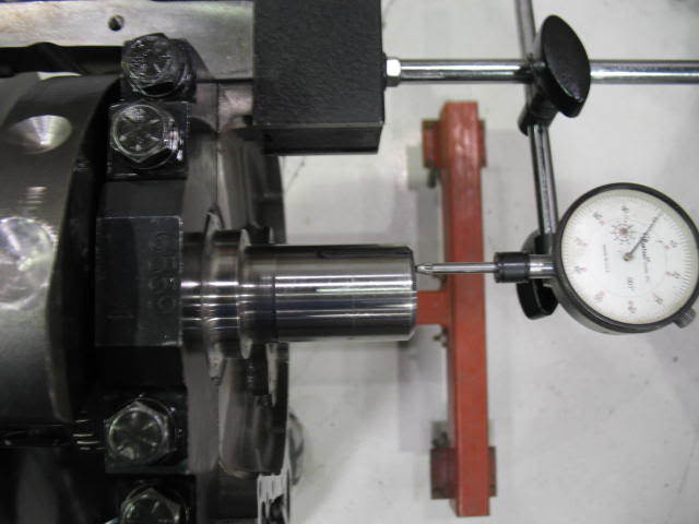
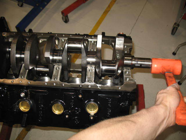
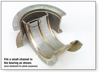
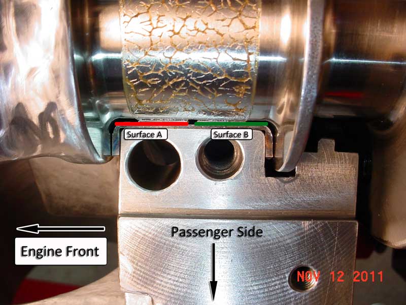
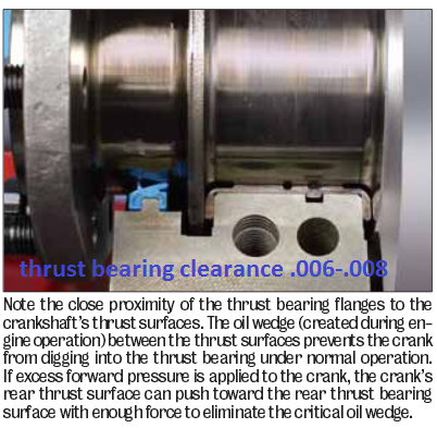
A simple modification to the upper thrust bearing may be beneficial in some engines. Install the upper thrust bearing in the block to determine which thrust face is toward the rear of the engine. Using a small, fine tooth, flat file, increase the amount of chamfer to approximately .040" (1 mm) on the inside diameter edge of the bearing parting line. Carefully file at the centrally located oil groove and stroke the file at an angle toward the rear thrust face only, as shown in the illustration below. It is very important not to contact the bearing surface with the end of the file. The resulting enlarged ID chamfer will allow pressurized engine oil from the pre-existing groove to reach the loaded thrust face. This additional source of oiling will reach the loaded thrust face without passing through the bearing clearance first (direct oiling). Since there may be a load against the rear thrust face, oil flow should be restricted by that load and there should not be a noticeable loss of oil pressure. This modification is not a guaranteed "cure-all". However, the modification should help if all other conditions, such as surface finish, alignment, cleanliness and loading are within required limits.
WATCH THIS VIDEO
NEVER USE A TORQUE WRENCH LIKE A BREAKER BAR TO LOOSEN BOLTS as it TENDS TO QUICKLY DESTROY ITS ACCURACY & consistency
http://www.youtube.com/watch?v=zgwwOJ0B ... r_embedded
http://www.chevelles.com/forums/showthread.php?t=379622
ONE youve installed the engine in the car, and ASSUMING you've PRE-PRIMED the oil pump and oil runs out of the rockers,if it takes more than 40 ft lbs to get it to turn freely , without the spark plugs installed, or accessory belts on, or the transmission installed, somethings binding or the clearances are wrong, Id start by loosening all the rockers and see if it makes a difference, you would not be the first guy to think everything's adjusted correctly yet have the valves not adjusted correctly
read these threads above
if youve used a quality assembly lube, and have the correct clearances it should require NO MORE than 40 ft lbs of force to start an engine too turn and under 20 ft lbs to keep it spinning, and thats with new rings in a newly honed bore, that effort required should drop rapidly to the point that less than 20 ft lbs are required to spin a short block after its been well oiled and rotated dozens of times.
one factor some new guys over look is that rods and bearings are designed with one side having a bevel that faces the counter weights and a non-bevel edge facing the matched rod
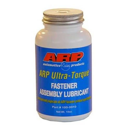
In any application where your tightening a nut on a stud , such as on the outer threaded ends of main cap studs or head bolt studs,or rod bolts, youll want to use a lube on the threads that gives consistent torque reading from your torque wrench indicating the correct bolt or stud TENSION, oil and MOLY assembly lube and various thread sealants do not always do that,the end in the blocks course threads have thread sealant, the fine threads on the outer end require a totally different lubricant
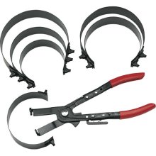
GOOD and VERSITILE
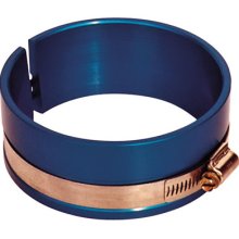
WORKS GREAT BUT LIMITED TO A NARROW BORE RANGE AND EXPENSIVE
http://www.amazon.com/KD-Tools-850-Diam ... 0002STSMG/
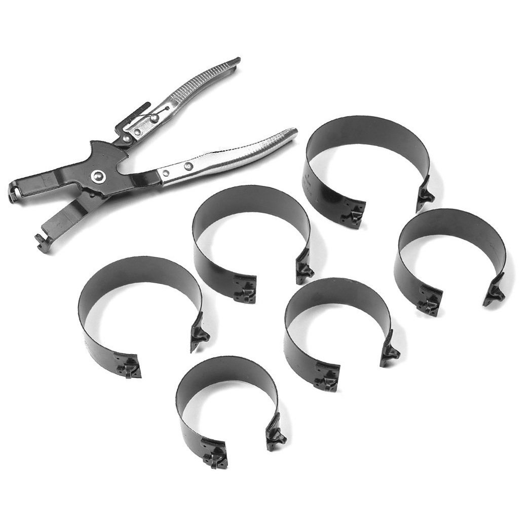
http://garage.grumpysperformance.co...g-and-installing-connecting-rods-pistons.247/
http://garage.grumpysperformance.com/index.php?threads/piston-ring-gaps.2837/#post-7989
http://garage.grumpysperformance.co...ng-and-basic-piston-ring-info-youll-need.509/
http://garage.grumpysperformance.com/index.php?threads/installing-rings-in-piston-grooves.9490/
http://garage.grumpysperformance.co...ng-piston-ring-grooves-and-related-info.1797/
http://garage.grumpysperformance.com/index.php?threads/maximizing-piston-to-bore-ring-seal.3897/
http://garage.grumpysperformance.co...roove-depth-clearance-effects-ring-seal.5454/
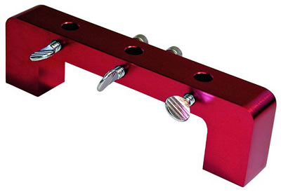
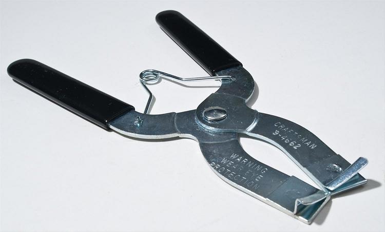
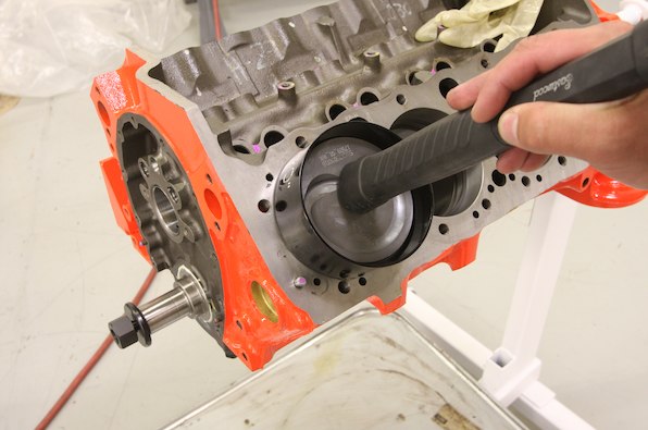
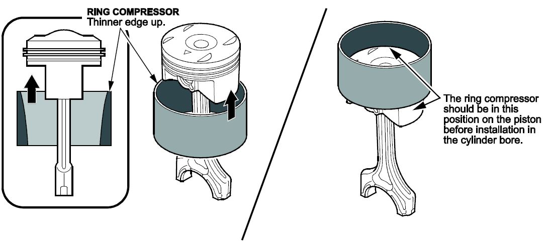
this type (ABOVE) handles many applications but the cheap versions are a P.I.T.A. to work with
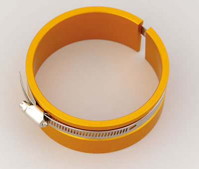
BTW when you go to buy a ring compressor....this type(ABOVE & BELOW) works far better than the others, but its specific to a very limited range in bore size applications
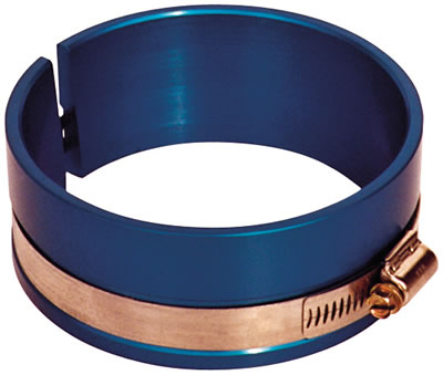
http://store.summitracing.com/partdetail.asp?autofilter=1&part=PRO-66766&N=700+115&autoview=sku
Proform 66766 $31
Tech InformationInstallation Tips
Engine Bearing Installation and Fitting Tips
When measuring bearing measurements, they should always be taken at 90-degrees to the parting line to determine the minimum clearance. If measuring the bearing wall thickness, use a special micrometer with a ball anvil to fit the curvature of the bearing ID. The best way to determine bearing clearance is to measure the bearing ID with the bearings installed in the housing and the bolts torqued to the specified assembly torque. Use a dial bore gauge to measure the bearing ID at 90-degrees to the parting line, then subtract shaft size from bearing ID to determine the clearance. If the dial bore gauge is zeroed at the actual diameter of the crankshaft journal to be installed, the dial bore gauge will then read clearance directly and the subtraction calculation can be eliminated. About .001" clearance per inch of shaft diameter is a good rule of thumb. Increasing that by about .0005" will add a little margin of safety when starting out, especially for rods. Example: .001" X 2.100 = .0021" then add .0005", so starting out set clearance at .0026" for a 2.100 shaft.
If clearance adjustments need to be made, use either an extra clearance part for more clearance or an undersize part for less clearance. It is permissible to mix sizes if less than .001" adjustment in clearance is desired. When mixing sizes for a select fitting: a) never mix parts having more than .0005" difference in wall size; b) and always install the thickest wall shell in the upper position if installing a rod bearing or the lower position if installing a main bearing. When working with a reground shaft, always measure assembled bearing ID's first. Next have a shaft sized to produce the desired clearance since there are no extra clearance parts available for undersize shafts.
When measuring a bearing ID or wall thickness, avoid measuring at the parting line. The diagram illustrates there is a parting line relief machined into nearly all bearing shells. This relief is to allow for any mis-match between upper and lower shells due to tolerance differences, or possibly resulting from cap shift or twist during assembly. To determine bearing wall eccentricity or assembled bearing ID ovality, measure at a point at least 3/8" away from the parting line.
When installing any bearing DO NOT ATTEMPT TO POLISH THE BEARING RUNNING SURFACE WITH ANY TYPE OF ABRASIVE PAD OR PAPER. Bearing overlay layers are extremely soft and thin – typically .0005" on high performance parts. These thin layers can easily be damaged or removed by an abrasive media. Because the overlay layer is electroplated, it may exhibit microscopic plating nodules that make it feel slightly rough. The nodules are the same material as the rest of the plated layer and will quickly be flattened by the shaft. Bearing surfaces can be lightly burnished with solvent and a paper towel if desired.
Arriving at the correct choice of a high performance bearing for any given racing application is much like determining what clearance works best. From past experience, our knowledge of the intended usage and common sense can guide us in making an initial choice. Next, we can fine tune the selection process based on those results. The information given here is intended to aid in the initial selection as well as the fine tuning process.
The following table serves as a brief overview of the features included in each of the special Clevite 77® brand high performance bearing series.
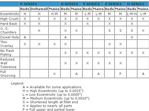
http://www.stealth316.com/misc/clevite-77-rod-main-bearings.pdf
http://www.scatcrankshafts.com/product-search/
https://www.summitracing.com/parts/sca-6570020
sure the earlier bore size is listed
for those of you un-aware of rod journal sizes
Chevy Smallblock V8 Crankshaft Journal Sizes
Gen.I, "Small Journal"
265...Mains-2.30"-Rods-2.00"
283...Mains-2.30"-Rods-2.00"
302...Mains-2.30"-Rods-2.00"
327...Mains-2.30"-Rods-2.00"
Gen.I, "Medium Journal", includes "Vortec" 305 and 350 thru '98
262...Mains-2.45"-Rods-2.10"
267...Mains-2.45"-Rods-2.10"
302...Mains-2.45"-Rods-2.10"
305...Mains-2.45"-Rods-2.10"
307...Mains-2.45"-Rods-2.10"
327...Mains-2.45"-Rods-2.10"
350...Mains-2.45"-Rods-2.10"
Gen.I, "Large Journal"
400...Mains-2.65"-rods-2.10"
Non-production Gen.I combination, using Gen.I 400 crank in Gen.I 350 block
383...400 crank, Mains cut to 2.45"-Rods-2.10"
Non-production Gen.I combination, using Gen.I 350 crank in Gen.I 400 block
377..."Spacer" or "thick" main bearings with 350 crank-Rods-2.10"
Gen.II, "Medium Journal", includes "L-99" 265, "LT-1" 350, "LT-4" 350
265...Mains-2.45"-rods-2.10"
305...Mains-2.45"-Rods-2.10"
350...Mains-2.45"-Rods-2.10"
Non-production Gen.II combination, using Gen.II 265 "L-99" crank in Gen.II 350 block
302...Mains-2.45"-Rods-2.10"
Gen.III, includes '97-2005 "LS-1" Corvette, Firebird, Camaro
345...Mains-2.558"-Rods-2.10"
Corvette "ZR-1", DOHC, "LT-5"
350...Mains-2.76"-Rods-2.10"
narrow bearings have beveled edges to prevent the edge of the crank journal radias touching the bearing, h series are beveled edge bearings designed for higher loads so they are a bit harder
70-95 454 Chevy Clevite performance main bearing set. Clevite 77 "H" Series bearings have a medium level of eccentricity, high crush, and rod bearings have a hardened steel back and thin overlay. These bearings also have enlarged chamfers for greater carankshaft fillet clearance and are made without flash plating for better seating. Use "H" Series bearings with crankshafts that have oversize fillets and where engines run in medium to high RPM range.

http://garage.grumpysperformance.co...ng-piston-pin-height-compression-height.5064/
http://garage.grumpysperformance.co...n-wrist-pins-one-really-over-looked-part.978/
if you find the rotating assembly is more difficult to rotate than you expected, you may want to verify some clearance issues that get over looked at times,
theres also some, other potential issues,
theres a slight potential for the piston wrist pins too not rotate effortlessly in the piston pin bores ,
that may add to the difficulty in rotating the assembly in the block.
the piston rings must have vertical and back clearance in the piston ring grooves
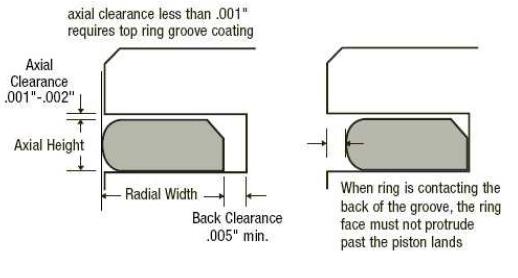
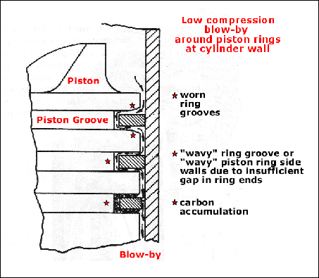

Piston Ring Groove Clearance
Pistons are grooved to fit rings that seal the cylinder’s compression and allow for lubrication of the cylinder walls. Piston rings come in a set. There are two compression rings. The top ring is affected by the most cylinder compression pressures. The second compression ring reinforces the top ring. The third ring down is the oil ring. It controls lubrication between the piston and cylinder bore.
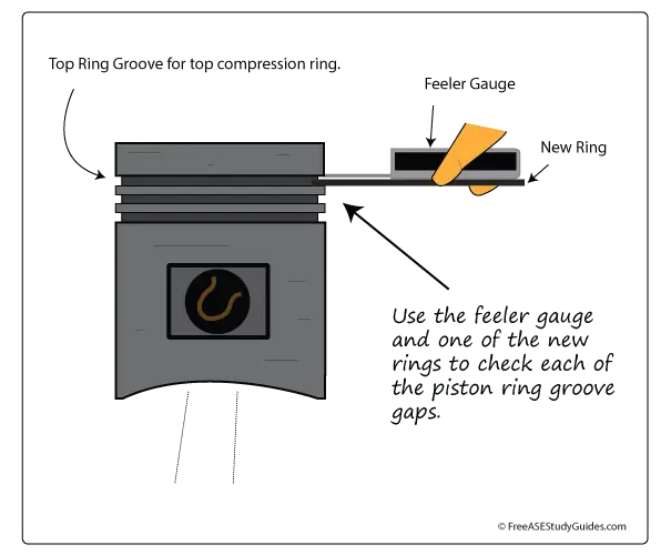
Place the new ring into the top piston groove, and then place a feeler gauge into the gap between the new ring and the upper land. Move around the pistons groove and obtain a few measurements. Compare this reading to specifications. If this reading is too much and the gap is too large, the piston must be replaced. The top ring takes the most compression. This causes the ring to slap against and wear the lands in the piston groove.
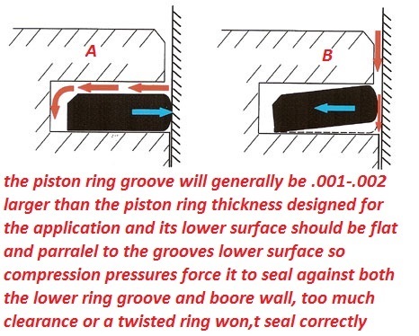
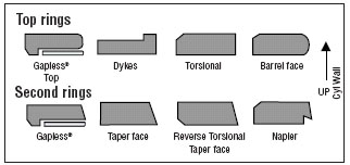

and of course the pistons must have the correct piston too bore clearance. and connecting rod can only be installed facing one direction


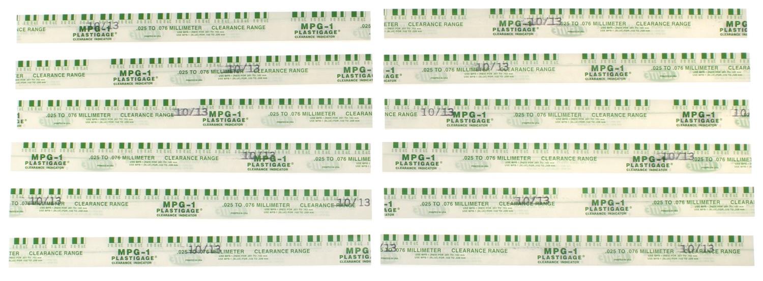
you can use all the precision measuring tools you may have but the truth is always evident in cross checking with plasti-gauge
www.summitracing.com
garage.grumpysperformance.com
garage.grumpysperformance.com
garage.grumpysperformance.com
garage.grumpysperformance.com
garage.grumpysperformance.com
garage.grumpysperformance.com
I use both micrometers and snap gauges and cross check with plasti-gauge
and yes when you compare the crushed width of the plasti-gauge youll find it rarely falls as an exact match to the bar chart tape that is packaged with it so you can judge clearance based on crush width
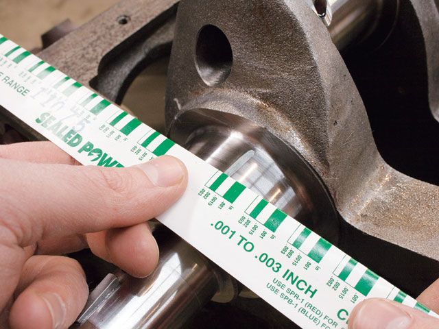
http://garage.grumpysperformance.com/index.php?threads/bearing-clearances.2726/


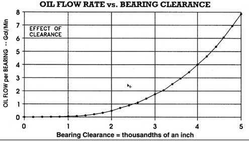
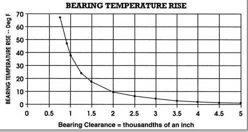
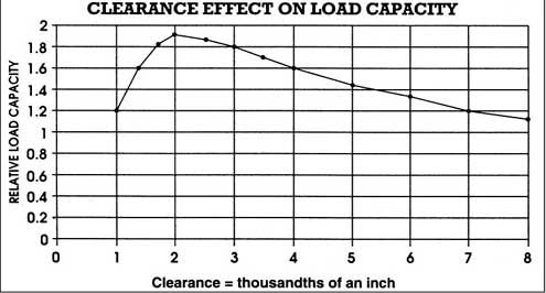
as a general rule you select .001 bearing clearance for every inch of bearing journal diameter,
Rod bearings 0.002 - 0.025" , side clearance 0.010 - 0.020"
Main bearings 0.002 - 0.003" for most engines ( 0.020-0.025 bearing clearance on small blocks, .025-.027 bearing clearance is about ideal, on big blocks ), 0.005 - 0.007 crankshaft end play
http://garage.grumpysperformance.co...ng-clearances-engine-builders-magazine.11965/
http://garage.grumpysperformance.com/index.php?threads/oil-system-mods-that-help.2187/
the lubed crank shaft will take a bit more effort to start it rotating than it takes to keep it rotating, as the surface tension and lube shear takes a bit of effort to get it rotating, thats one reason the torque beam style torque wrench is preferred too check the resistance , as you get to see both starting and rotational resistance on the wrench scale, rather than the click style torque wrenches design for verifying the rotational resistance, and be aware that the resistance should NOT significantly change as the crank shaft rotates through its full 360 degrees, if it does it may indicate a block that needs to be line honed to cure a slight block warp- age issue or a bent crankshaft, a dial indicator and an accurate bore gauge and a good solid stand for the indicator can help you locate the cause.
theres zero doubt you can build some of the more common SBC and BBC engines with either a mix of O.E.M. and and aftermarket components,
BE AWARE NOT ALL POTENTIAL PARTS COMBOS ARE COMPATIBLE
or go with just aftermarket components through out.. It should be obvious that you'll need to do some research , and calculations on,
rod length, bearing clearances, compression height, compression ratio, quench, and valve train geometry,intended port flow, valve lift,
and carefully verify the clearance , and valve train geometry issues before ordering components, and during the actually assembly.
https://www.amazon.com/dp/B06VXC1FPL/ref=nav_timeline_asin?_encoding=UTF8&psc=1


assembling and installing connecting rods/pistons
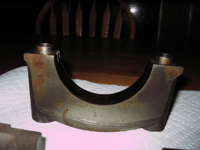
He Measured .0004" - 4/10,000 th of an inch #5 MAIN CAP BORE DISTORTION TORQUED DOWN TO SPECS WITH THE OIL PUMP ON. I DON'T.LIKE IT. IT SHOULD BE +/- .0001" TOLERANCE. +/- .0002" INCH MAX.
garage.grumpysperformance.com

as to the rotational smoothness, be aware that, all assembly lubes and oil on blocks bore the rings ride over and all bearing surfaces, coated with oil and assembly lube provide a surface shear tension that must be broken before the crank turns,
so its not un-usually for the rotating assembly after the pistons and rings are installed, too require lets say 35 ft lbs to get the assembly too start too spin ,but only 15-26 ft lbs to keep in rotating , (low tension rings provide less drag) you can generally call the piston ring manufacturers and they should know approximately what torque reading on the crank snout, a socket and a torque wrench will require to have the engine assembly rotate with their rings installed.
a crank snout, turning socket, but if that short block assembly, takes over 35-40 ft lbs too start it rotating, once its assembled without cylinder heads attached, you've got serious issues, like cam lobe to connecting roods hitting or a connecting rod facing the wrong way on the crank journal, or the wrong size bearings, or the crank journals not the right size, badly polished or not round

that's why you'll need a torque beam deflection torque wrench to check that

https://www.amazon.com/Presa-Drive-...ocphy=9012039&hvtargid=pla-669567243785&psc=1
read the labels and load rates carefully before ordering they make inch lb, ft lb versions
1/4",
3/8"
and 1/2"
drive versions
and having an inch lb rated one helps at times $25 on amazon
https://www.amazon.com/Neiko-03727A...ocphy=9012039&hvtargid=pla-572951906812&psc=1
https://www.ebay.com/itm/224242691491?epid=23014633155&_trkparms=ispr=1&hash=item3435e7eda3:g:sBkAAOSw5MFfuDZS&amdata=enc:AQAGAAACoPYe5NmHp%2B2JMhMi7yxGiTJkPrKr5t53CooMSQt2orsSvtkx670Z0mbyfWqmxLFLYbSgftsPKn4P4%2BuyGMgnhW%2FjIce0dpW9M3RoBZspmh1OP12%2B1VAxoUJJj3RoXfTi%2BdPDYwWVpZhnEHOtxRJrO9BgZbW7EgR6P7ToLFxxssR3y9JK0MrcC1gFkn3SW32QlRm1jVDvf75zsqK4K6a3ZYjn8qwXzUYq6h4garZZxJfbfur3C7bxYsXM6Kd0RP%2Bc1qcqgfVJHBlQgVk4udvEWA36jrjTVJl5%2BCY4o1Ivq4bl7iQqsi7Hf9CMDhs1uIRQNOVZaGYqWg9k4J0UBWdzz8l8X%2FOqd9t3DRpXca5J9mjp65pFUANhTN3TfDEtTpSfCkWmlHnqMmYCOvLSwvD1QZMXkSF0aOKRqnGjBtvV0xFal9s9EMVlX8gRTesUivsA%2FodQ%2FlEYPwFdqVXGP1WdDLW4J90gTGRKzasKw%2FOHt7XrubOgzy515noBgagP9s2M1iGfVGLK2dXotGyaTVcSbvCHNSmbSUvaKVX7Jm7hgX3UZIvrnEYFwbpAec4a0%2BqRPqov5SRFpkQ0DGE9tAvXszC8xwzF9%2F%2FxSK%2FPmvpoJ%2FxGmwoio1ZR88UMdq6GHkjzFQIpQE946bHSep0BzmPBPXyILyvAcxWgs1vPcytjTHBLwAMI0lLADbjgWGGJUMAl8nR2wLczSCeJC7Sd5lIfZ%2FPNxz8aB0qf73TtmocTHjhkcVWW3C0bmckieELPrUXPfLp6ltQmqHsGXDFoITaQRs0mPFQ4TRBoUyYcGtfrS8V8XHcQ0TZtCtqoni0tUGwbdHFKQGYpD%2FFFTpEYitoFjODdATrumb5yl7bb5fAiIRVou6oUBD75feDSqdDpB7G23g%3D%3D|ampid

Don,t forget too use a large rubber, leather or plastic mallet, lead hammer to gently beat the crank seated in the bearings, both forward and aft in the block several times , too seat the thrust bearing,
and of course use a dial indicator and plasti-gauge to verify clearances and too check clearances.
I'd alsp point out that all the main caps will need to be torqued in place in at least three stages to allow the block stress to disapate and equalize as the main caps are seated to the block and it helps to go back over the main cap bolts starting at the center and working outwards in a spiral as the caps are tightened at each torque stage.
YES READING LINKS WILL HELP A GREAT DEAL
http://garage.grumpysperformance.com/index.php?threads/thrust-bearing-wear.619/
http://garage.grumpysperformance.com/index.php?threads/precision-measuring-tools.1390/#post-68861
http://garage.grumpysperformance.com/index.php?threads/bearing-clearances.2726/
http://garage.grumpysperformance.co...ed-holes-in-bearings-shells.10750/#post-53298
http://garage.grumpysperformance.com/index.php?threads/precision-measuring-tools.1390/#post-44530
http://garage.grumpysperformance.com/index.php?threads/which-torque-wrench.342/#post-10864
Engine Balancing
Does anyone have tips on engine balancing? I bought an externally balanced 383 that ran fine in a 67 Chevelle with an automatic transmission. I had the new flywheel and clutch supposedly balanced to the flex plate that was in the Chevelle. I installed the 383 in my 1975 Corvette with a 4...
garage.grumpysperformance.com
http://www.superchevy.com/how-to/engines-drivetrain/4380-bearing-clearance-info/
https://www.chevyhardcore.com/tech-...ies-measuring-and-setting-bearing-clearances/
https://www.chevydiy.com/pre-assembly-guide-build-chevy-small-block-engines/
http://knowhow.napaonline.com/know-notes-measure-engine-bearing-clearance/
https://www.mahle-aftermarket.com/media/local-media-north-america/pdfs-&-thumbnails/cl77-1-205r.pdf
http://www.superchevy.com/how-to/engines-drivetrain/0707ch-main-bearing-clearance/
https://www.enginebuildermag.com/2013/03/bearing-clearances/
https://blog.k1technologies.com/how-to-check-bearing-clearances
if your experiencing issues and the crank won,t rotate in the main journals very smoothly , STOP and find out WHY or take the block and crank to a trusted local machine shop, further assembly will just cause problems with long term durability if the basics are not correct! REMEMBER YOUR BLOCK MAY NEED TO BE LINE HONED OR THE CRANK MAY BE BENT OR OUT OF DIMENTIONAL SPECS,THIS NEEDS TO BE VERIFIED AND IF REQUIRED, CORRECTED
theres at least a few hours of very worth while , and quite useful reading in this thread and links that will prevent you wasting time and money, keep in mind the sub links contain a huge wealth of additional info youll need
what seems to be over-looked in many engine builds is simply the fact you'll almost always DEEPLY regret jumping into the engine build with both feet and waving your check book as you sink ever deeper into piles of parts receipts and machine shop bills, rather than stepping back with a legal pad, and a calculator and listing in minute detail exactly what you want to accomplish, and taking the time and effort too list and check out in detail what each machine shop procedure costs, why its required and how much each components costs, what your options are and how each component will add too or benefit the completed combo (or in some cases cause you time and grief)
stepping back and thinking things through in detail and listing the cost and potential problems and finding the solutions BEFORE you dive into the process may be a lot less fun, but in the long term its sure to cost less and result in a far better finished project!
you might be amazed at what a couple hours research into the subject will do to help you build a much more durable engine, and actually reading thru links and sub-links and asking questions helps a great deal
https://www.carshopinc.com/product_info.php/products_id/49347/SPG1-12
http://garage.grumpysperformance.co...ting-rod-tools-than-some-guys-may-want.16414/

http://garage.grumpysperformance.co...ting-resistance-to-look-for.11312/#post-51472

yes I use both micrometers and snap gauges and cross check with plasti-gauge
and yes when you compare the crushed width of the plasti-gauge youll find it rarely falls as an exact match to the bar chart tape that is packaged with it so you can judge clearance based on crush width
http://garage.grumpysperformance.com/index.php?threads/bearing-clearances.2726/
http://garage.grumpysperformance.co...piston-to-bore-clearance-on-your-block.14251/


OBVIOUSLY YOULL NEED A TOOL TOO CHECK ROTATIONAL RESISTANCE,
sears sells them for about $20
home depot for $15
http://www.homedepot.com/p/Powerbui...e-Torque-Wrench-644044/203116749?N=5yc1vZc6ev
http://www.sears.com/craftsman-3-8-...999000&pla=&kispla=00932999000P&mktRedirect=y
http://garage.grumpysperformance.com/index.php?threads/bolts-a-bit-of-useful-info.4868/#post-13372
THIS BEAM STYLE TORQUE WRENCH IS THE TYPE TORQUE WRENCH YOU WANT TO CHECK ROTATIONAL RESISTANCE, these come in at least three torque ranges
for checking the rotational resistance you'll want the lower rated version, that reads 0-75 ft lbs or in inch lbs

BUT NOT WHAT YOULL USE TO TIGHTEN HEAD BOLTS


if your SBC engine requires over about 30 ft lbs to get it started rotating,
or over about 25 ft lbs to keep it rotating,
youve got issues that you need to look into before further assembly
use lots of moly assembly lube on the bearing surfaces
BBC will require about 3- 5 lbs more effort, on each point
(starting and keeping it rotating, once all 8 pistons are installed)
as the rings lap into the bores and bearings seat, the resistance should rather rapidly be reduced a few ft lbs.
BORES should be lightly oiled and bearings coated with assembly lube.
http://www.4secondsflat.com/Thrust_bearing_failures.html
http://garage.grumpysperformance.com/index.php?threads/thrust-bearing-wear.619/


Assembling A Short Block For The Home Engine Builder
We've covered all of the sub- assemblies for our 383 Mopar Slaghammer build, and now it's time to turn this pile of parts into an engine. Here we cover beari...

keep in mind the assembly lube or even oil on the bearing surfaces has a surface shear limit,
that why the crank is harder to start rotating but the required effort to keep it spinning is significantly lower,
your initial effort to twist the crank must break that surface tension on the lube,
once its sheared the lube forms a lubricating layer and metal to metal contact is prevented as the lube forms a barrier layer


NEVER GUESS, DEAL IN PROVEN FACT!
Id get out the plasti-gauge and check clearances, don,t guess , know exactly what your dealing with!
if the clearance falls in spec and the bearings look decent they can be re-used, but its foolish to do so if they look overly dirty, worn or don't have the correct clearances
lots of moly assembly lube and spraying any potential moving contact surface with moly spray (like bearings ,lifters rockers) and liberal use of moly assembly lube during the break-in process helps reduce wear issues
pre-spraying all bearing and valve train components with a moly based spray, helps embed micro moly lubricants in the metallic surface micro fissures , a good paste lube like cranes assembly lube over the spray surface helps insure a good lubricant surface coating, that is far stronger than just the ZINC and PHOSPHATES in oil

Take the effort and time too CAREFULLY.. read links and SUB LINKS,
THIS is almost mandatory on this web site!
if you want all available useful & related info
http://garage.grumpysperformance.co...earances-and-journal-surface.9955/#post-38385
http://garage.grumpysperformance.com/index.php?threads/bearing-clearances.2726/#post-26440
http://garage.grumpysperformance.co...hrust-bearing-failure-info-related-info.1138/
http://garage.grumpysperformance.co...ing-parts-and-a-logical-plan.7722/#post-72126
http://garage.grumpysperformance.com/index.php?threads/can-you-reuse-bearings.5544/
http://garage.grumpysperformance.com/index.php?threads/bearing-clearances.2726/#post-7077
http://garage.grumpysperformance.co...shaft-journal-surface-finnish.2728/#post-7079
https://www.mahle-aftermarket.com/m...b-2-1114-engine-bearing-failures-brochure.pdf
http://garage.grumpysperformance.com/index.php?threads/precision-measuring-tools.1390/#post-68194
http://garage.grumpysperformance.com/index.php?threads/causes-of-bearing-failure.2727/#post-13056
http://garage.grumpysperformance.com/index.php?threads/don-t-beat-that-damper.83/#post-14101
http://garage.grumpysperformance.com/index.php?threads/thrust-bearing-wear.619/#post-10925
http://garage.grumpysperformance.co...tion-of-crank-durring-short-blk-assembly.852/
http://garage.grumpysperformance.com/index.php?threads/assembly-lube-summary.6352/#post-68508
http://garage.grumpysperformance.co...ear-articles-you-need-to-read.282/#post-57371

I generally use CLEVITE (H) bearings as they have a bit more edge to crank journal edge radias clearance for the bearing shell to crank counter weight clearances
With the crank shaft alone in the main bearings, any inconsistency in the assembly lube thickness, or journal surface finish could and probably will cause a difference in rotational resistance or drag, if it spins fairly easily with a couple fingers on the crank snout with all the mains torqued down and your plastic-gauge checks and micrometers say the bearing clearances are correct your going to be fine, I generally look to have less than 5 ft lbs resistance , on keeping it rotating, once it starts to move, a properly installed strait crank in a properly honed set of main caps with properly clearances main cap bearings well coated with a 50%/50% mix of assembly lube and marvel mystery oil on the bearing crank surfaces and less than 10 lbs to get it to start rotating as the surface tension of most assembly lubes will resist rotation until it starts to rotate, then the resistance to rotation drops off rapidly,
on a newly rebuilt engine the SHORT BLOCK (no heads installed) and with the bearings and cylinder bores oil coated, it should require LESS than 40ft lbs to get rotating and less to keep it rotating, a crank ALONE installed in the correctly tightened main caps should require LESS than 10 lbs to start rotating and far less to keep spinning.
a used engine will develop a bit looser clearances and require LESS force to rotate after the heads are removed.
on a racing engine the crank alone can easily be spun in the main bearings with your fingers and over about 25-28 lbs resistance when using low drag rings usually indicates a problem
a used engine will develop a bit looser clearances and require LESS force to rotate after the heads are removed.
yes having an accurate torque wrench is mandatory when you build an engine, yes having the piston to bore clearance, ring end gap and bearing clearances correct helps a great deal, and yes low tension rings DO tend to reduce the resistance to rotation, and yes, some assembly lubes DO make the engine a bit harder to start the rotation.
obviously a slightly bent crank, inconsistent bearing clearances, non-round crank journals , rough polish surfaces on journals or a block that needs to be line honed or a bent cam or tight cam bearing journals or improper bearing clearance or dry bearing surfaces tend to increase resistance.
IF your engine resists rotation to a higher torque load rate
FIND OUT WHATS BINDING BEFORE PROCEEDING FURTHER, you sure won,t be the first guy to have installed something incorrectly or had the wrong clearance's but catch it BEFORE proceeding further

HUSKY $88 (worked rather well, over all I was pleased)
http://www.homedepot.com/p/Husky-1-2-in-Click-Torque-Wrench-H2DTW/202916180?N=5yc1vZc6ev
CONNECTING ROD SIDE CLEARANCE AND THRUST BEARING CLEARANCES MUST BE CORRECT.
CONNECTING RODS AND PISTONS MUST FACE THE CORRECT DIRECTION AND RING END GAPS MUST BE CORRECT AS WELL AS BEARING CLEARANCES, and THE OIL PUMP MOUNT STUD MUST NOT TOUCH THE REAR MAIN BEARING SHELL
now once you add all the connecting rods, pistons and rings obviously resistance to rotation will increase as rings slide along bore walls and you've added rod bearings, Keeping in mind that we are discussing a short block with no heads installed yet and rings riding on well oiled cylinder walls, that should require less than 40 ft lbs to spin, less than 30 lbs of resistance is ideal, because an engine turns more easily with the heads removed or the spark plugs removed.
a crank bye it self ,sitting in a properly machined block with the bearings in place, having been coated with a decent assembly lube, (I generally mix CRANE CAMS ASSEMBLY LUBE WITH MARVEL MYSTERY OIL IN ABOUT A 50%/50% mix on bearings) and the main caps torqued in place should require no more that 10 ft lbs to start to spin (MAXIMUM) and in most cases noticeably less to keep it spinning, in-fact most are easily spun with finger pressure alone.
if it takes more than 10 ft lbs somethings either not machined correctly or your clearances or lube are wrong.
after you add the rods and pistons with the rings its resistance to rotation obviously increases but should still be UNDER 40 ft lbs to spin an assembled short block,If your carefully checking clearances you should see a minimal increase in resistance to the crank rotation, during assembly, as each piston assembly is added and torqued into place as ring drag increases resistance but the bearings should add little or any drag if properly sized and lubed.
obviously youll want to check the piston to bore clearance at several locations along the circumference of the bore to piston clearance, and check the blocks cylinder bore for consistent diam. and the bore being truly round in shape and but don,t forget to check the piston ring groove back clearance in the ring grooves and the ring end gaps plus look for piston pin bind in the piston pin bore, look for rod journals that are tapered or out of round and connecting rods with a big end thats not round or bearing that are not consistent in diameter across the bearing bore, but Ive also occasionally seen guys try to install rods without checking side clearance or who failed to get the correct side of the connecting rods facing each other or guys using rod bearings that didn,t have the correct edge bevel to clear the journal s radias edge, usually the narrower clevite (H) series have extra clearance
Get out the torque wrench and with the damper bolt installed turn the crank,and while its yet to have the rods and pistons installed, and its lying in its bearings, IT SHOULD TAKE ABOUT 10-12 ft lbs OR LESS to get it moving, and LESS than 10 lbs to keep it moving.
EVEN IN NEW MAIN BEARINGS, it should REQUIRE EVEN LESS ONCE IT LAPS INTO PLACE WITH THE ASSEMBLY LUBE
IF it takes more force theres a clearance issue or the crank or block needs to be checked carefully for straightness, journal tapper and roundness and surface finish and the bearings need to be checked for clearance and proper installation and crush,remember if it won,t turn or spin easily STOP RIGHT THERE and find out why! don,t forget to check the TRUST BEARING fore and aft movement/CLEARANCE
once youve installed EACH connecting rod, you'll want to do the test again, remember each piston with its rings adds drag, AND YOU NEED TO VERIFY THE RING GAPS AND PISTON GROVE DEPTH AND CLEARANCE TO ALLOW THE RINGS TO SLIDE BACK INTO THE GROOVES, but in a well oiled cylinder,its not going to add a huge increase, in drag, as the rings ride on an oil film that prevents incorrect full surface physical contact, between the ring face and bore walls, and the bore surface will lap into the rings and vice versa during the break-in process.
IVE dunked my piston/ring assembly's in a can of MARVEL MYSTERY OIL just before installation with a ring compressor and have never seen the slightest indication of problems either on ring sealing getting the rings broken in, or on tearing the engines down later for inspections the amounts not that great, ideally each one installed adds a bit of resistance but at no time should the short block take over 40 ft lbs ABSOLUTE MAXIMUM to start it spinning,and LESS than 20 lbs to keep it moving, even with all the rings and pistons installed,yes you need to verify the bearing clearances during assembly and IT SHOULD take between 20lbs-25 lbs to start it spinning if the clearances are correct! and LESS than 20 lbs to keep it moving
IF it takes over 40 ft lbs to get it rotating ,youll need too DISASSEMBLE and FIND OUT WHY!
when you get the crank polished take the time and effort to clean out any cross drill oil feed passages and to very carefully de-burr the passage opening edges, as this is a very commonly overlooked issue, below is what at first looks like a perfectly polished crank, with oil feed passages to the rod bearings, but the deep scratches the oil feed passage openings left in the rod bearing surfaces bare witness, after a single rotation, during a trial assembly show they are HARDLY burr free or ready for use, and obviously he failed to check each rod bearing during the assembly process, and probably ignored , what was very likely un-even or rather excessive resistance to the crank rotation. which should never exceed about 40 ft lbs even with all 8 rod bearings and pistons installed


http://garage.grumpysperformance.com/index.php?threads/precision-measuring-tools.1390/
http://garage.grumpysperformance.co...n-my-3rd-rear-main-seal-bbc.11084/#post-49384
http://garage.grumpysperformance.com/index.php?threads/replacing-a-gen1-rear-main-seal.474/#post-585
http://garage.grumpysperformance.co...gine-project-dart-shp.3814/page-12#post-17457
http://garage.grumpysperformance.co...od-rod-length-too-stroke-info.510/#post-10311
READ THIS LINKED INFO
Common assembly clearances

GET THE RING END GAP TOO TIGHT AND WHEN THE RINGS EXPAND WITH ENGINE HEAT THE ENDS TOUCH THE RINGS LOCK IN THE BORE AND THE PISTON LANDS SHEAR OFFGET THE GAP A BIT TOO LARGE AND YOU MIGHT BURN A BIT MORE OIL OR LOOSE SOME COMPRESSION, YOU'LL SEE A CHART LATER IN THE THREAD, BUT GENERALLY YOU'LL WANT .0045-.0065 PER INCH OF BORE DIAM. FOR A RING END GAP

(ALWAYS consult your piston manufacturer for recommended clearances. Many pistons require a tighter bore)
Piston to bore 0.0055 - 0.0065" ( measured at centerline of wrist pin, perpendicular to pin)
Piston ring gap MINIMUM end clearances Top 0.022"
2nd 0.016"
Oil 0.016"
Wrist pin 0.0006 - 0.0008" in piston, 0.0008 - 0.0010" in rod for full floating pin (End play 0.0 - 0.005"
Rod bearings 0.002 - 0.025" , side clearance 0.010 - 0.020"
Main bearings 0.002 - 0.003" , 0.005 - 0.007 crankshaft end play
Piston to head clearance 0.035 MINIMUM including gasket (steel rods), 0.060" MINIMUM aluminum rods
Valve to piston clearance MINIMUM 0.020" exhaust , 0.010" intake NO VALVE FLOAT
Recommended: 0.080 intake, 0.100 Exhaust (steel rods) 0.100 intake, 0.120 Exhaust aluminum rods


Ive got a full set of Mitutoyo mics 1" 2" 3" 4" 5" I paid several hundred dollars for,
and a cheap duplicate set from northern tool mics along with half a dozen different digital calipers and so far they all are consistent enough that theres not been any effective difference.
now I fully agree theres a very noticeable difference in quality , that's not debatable,if you need to know that last couple ten thousands of an inch your wasting any money spent at HF MICROMETERS , the accuracy is just not available but if your just measuring something like a piston ring thickness, or crank journal diam. and getting within 2 ten thousands plus or minus is ok, they all work well enough, and for most hobby level builders I think thats true! especially when I see guys installing rings right out of the box without checking end gaps, or even using plasti-gauge to check bearing clearances
and yes I constantly cross check them against each other, in fact I generally use several mics and a digital caliper during engine assembly, and constantly recheck against the precision gauge blocks and feeler gauges


most piston compression rings have a dot on the upper surface to indicate the side designed to face the top of the piston

ideally the pressure above the piston gets behind the top compression ring and increases the force holding the ring face to the bore surface, noticeably more than the ring tension alone can do.

http://www.enginelabs.com/engine-tech/e ... ng-tension

If you put together a stock 400 Chevy, and put standard tension rings in it, it’s probably going to take about 30 to 35 foot-pounds of torque to turn that shortblock,” Massingill said. “If you put it together with the rings that we utilize [for the Engine Masters Competition], it’s going to take about eight or nine pounds. Can you imagine, at 7,000 or 8,000 rpm, the difference that that is? It can easily be 30-35 horsepower.”
BTW
IVE dunked my piston/ring assembly's in a can of MARVEL MYSTERY OIL just before installation with a ring compressor and have never seen the slightest indication of problems either on ring sealing getting the rings broken in, or on tearing the engines down later for inspections
remember that when you go to re-install the compressed piston rings, and piston in the engine block,bores that dunking the piston in MARVEL MYSTERY OIL , just before, its slid into the ring compressor will coat the rings and bore contact areas enough to prevent many small problems that insufficient lube might case


bearings AND connecting rods have an inner facing side and outer side the inner side facing the matching rod has far less edge clearance because they don,t need the radias that is required for the edge of the crank journals

https://www.youtube.com/watch?v=8GVQiYAVSDQ
btw


http://www.tooltopia.com/fowler-72-646-300.aspx

assembling and installing connecting rods/pistons
He Measured .0004" - 4/10,000 th of an inch #5 MAIN CAP BORE DISTORTION TORQUED DOWN TO SPECS WITH THE OIL PUMP ON. I DON'T.LIKE IT. IT SHOULD BE +/- .0001" TOLERANCE. +/- .0002" INCH MAX.
garage.grumpysperformance.com
heres the good assembly lube (I usually add about 10% oil too the assembly lube,to get it easy to smear on surfaces during the assembly process)
http://www.cranecams.com/index.php?show ... l=2&prt=15

Ive generally found the H-series bearings are the best choice
MORE USEFUL INFO

BE 100% SURE that the oil pump bolt or STUD doesn,t protrude past the inner main cap surface , because if it bears on the rear main bearing shell it will almost always result in a quickly failed rear bearing
failure to use the correct stud, bolt or nut,
OR OIL PUMP FOR THE APPLICATION,
or check clearances when mounting an oil pump,
can cause problems


ONE RATHER COMMON MISTAKE IS USING THE WRONG OIL PUMP STUD OR BOLT TO MOUNT THE OIL PUMP AS IF EITHER EXTENDS THRU THE REAR MAIN CAP IT CAN AND WILL BIND ON THE BEARING AND LOCK OR RESTRICT, SMOOTH ROTATION
http://engineparts.com/techbulletins/CL77-1-205R.pdf
viewtopic.php?f=50&t=1222
http://garage.grumpysperformance.com/index.php?threads/number-stamp-sets.1738/
http://www.chevyhiperformance.com/tech/ ... index.html
http://www.4secondsflat.com/Thrust_bear ... lures.html
http://www.circletrack.com/techarticles ... index.html
http://garage.grumpysperformance.com/index.php?threads/crankshaft-journal-surface-finnish.2728/
http://www.connectingrods.net/connectin ... tretch.php
http://www.circletrack.com/techarticles ... index.html
http://www.circletrack.com/enginetech/1 ... education/
http://engineparts.com/it_bearinginstall.asp
http://www.circletrack.com/enginetech/c ... ce_basics/
http://engineparts.com/it_crankinstall.asp
http://www.chevyhiperformance.com/tech/ ... index.html
the CRANE assembly lube is excellent but IVE used this grease mixed with a bit of mobile 1 oil as a substitute on bearings at times with excellent results
advance auto carries some
http://www.grumpysperformance.com/p1171 ... _large.jpg
http://shop.advanceautoparts.com/productdetail.aspx?MfrCode=VLV&MfrPartNumber=632&CategoryCode=3251
if your well lubed short block won,t spin at under 40 ft lbs once assembled even with high drag rings its a HUGE PROBLEM!
you need to use moly assembly lube
pull ALL the pistons and rods and verify the crank alone takes LESS than 15 lbs to spin, if not start checking clearances, once that's done verify the piston side clearances, then ring end gaps, ring to groove clearances in the pistons and the piston pin to piston pin bore side clearances,then remember the rods have an inner and outer facing side, and the bearings do also in most cases, check rod side clearance and thrust bearing clearance, and when your assembling the pistons & rods to the crank rotate the crank after each ones installed to find any unusual increased drag, a slightly bent rod, or the wrong bearings can add a good deal of drag
one factor to keep in mind is that rods typically have a side that rides against its matched companion and a side thats BEVELED for clearance on the crank journals radias EXAMPLE


notice the top rods non-beveled side that faces the matching rod is up, but on the lower rod the the beveled side that faces the crank counter weight is up on the lower rod
notice how one side of the bearing holding section has a radias (left)(GOES TOWARD CRANK COUNTER WEIGHT) but the opposite sides flush (right) (FACES MATCHED ROD)
you really need to read thru these threads
http://www.circletrack.com/howto/1818/index.html


btw spray the bearing and the crank surfaces, and the plastigage with WD40 before you measure clearances and it won,t tend to stick as much


A simple modification to the upper thrust bearing may be beneficial in some engines. Install the upper thrust bearing in the block to determine which thrust face is toward the rear of the engine. Using a small, fine tooth, flat file, increase the amount of chamfer to approximately .040" (1 mm) on the inside diameter edge of the bearing parting line. Carefully file at the centrally located oil groove and stroke the file at an angle toward the rear thrust face only, as shown in the illustration below. It is very important not to contact the bearing surface with the end of the file. The resulting enlarged ID chamfer will allow pressurized engine oil from the pre-existing groove to reach the loaded thrust face. This additional source of oiling will reach the loaded thrust face without passing through the bearing clearance first (direct oiling). Since there may be a load against the rear thrust face, oil flow should be restricted by that load and there should not be a noticeable loss of oil pressure. This modification is not a guaranteed "cure-all". However, the modification should help if all other conditions, such as surface finish, alignment, cleanliness and loading are within required limits.


WATCH THIS VIDEO
NEVER USE A TORQUE WRENCH LIKE A BREAKER BAR TO LOOSEN BOLTS as it TENDS TO QUICKLY DESTROY ITS ACCURACY & consistency
http://www.youtube.com/watch?v=zgwwOJ0B ... r_embedded
http://www.chevelles.com/forums/showthread.php?t=379622
ONE youve installed the engine in the car, and ASSUMING you've PRE-PRIMED the oil pump and oil runs out of the rockers,if it takes more than 40 ft lbs to get it to turn freely , without the spark plugs installed, or accessory belts on, or the transmission installed, somethings binding or the clearances are wrong, Id start by loosening all the rockers and see if it makes a difference, you would not be the first guy to think everything's adjusted correctly yet have the valves not adjusted correctly
read these threads above
if youve used a quality assembly lube, and have the correct clearances it should require NO MORE than 40 ft lbs of force to start an engine too turn and under 20 ft lbs to keep it spinning, and thats with new rings in a newly honed bore, that effort required should drop rapidly to the point that less than 20 ft lbs are required to spin a short block after its been well oiled and rotated dozens of times.
one factor some new guys over look is that rods and bearings are designed with one side having a bevel that faces the counter weights and a non-bevel edge facing the matched rod

In any application where your tightening a nut on a stud , such as on the outer threaded ends of main cap studs or head bolt studs,or rod bolts, youll want to use a lube on the threads that gives consistent torque reading from your torque wrench indicating the correct bolt or stud TENSION, oil and MOLY assembly lube and various thread sealants do not always do that,the end in the blocks course threads have thread sealant, the fine threads on the outer end require a totally different lubricant

GOOD and VERSITILE

WORKS GREAT BUT LIMITED TO A NARROW BORE RANGE AND EXPENSIVE


http://www.amazon.com/KD-Tools-850-Diam ... 0002STSMG/

http://garage.grumpysperformance.co...g-and-installing-connecting-rods-pistons.247/
http://garage.grumpysperformance.com/index.php?threads/piston-ring-gaps.2837/#post-7989
http://garage.grumpysperformance.co...ng-and-basic-piston-ring-info-youll-need.509/
http://garage.grumpysperformance.com/index.php?threads/installing-rings-in-piston-grooves.9490/
http://garage.grumpysperformance.co...ng-piston-ring-grooves-and-related-info.1797/
http://garage.grumpysperformance.com/index.php?threads/maximizing-piston-to-bore-ring-seal.3897/
http://garage.grumpysperformance.co...roove-depth-clearance-effects-ring-seal.5454/
this type (ABOVE) handles many applications but the cheap versions are a P.I.T.A. to work with

BTW when you go to buy a ring compressor....this type(ABOVE & BELOW) works far better than the others, but its specific to a very limited range in bore size applications

http://store.summitracing.com/partdetail.asp?autofilter=1&part=PRO-66766&N=700+115&autoview=sku
Proform 66766 $31
Tech InformationInstallation Tips
Engine Bearing Installation and Fitting Tips
When measuring bearing measurements, they should always be taken at 90-degrees to the parting line to determine the minimum clearance. If measuring the bearing wall thickness, use a special micrometer with a ball anvil to fit the curvature of the bearing ID. The best way to determine bearing clearance is to measure the bearing ID with the bearings installed in the housing and the bolts torqued to the specified assembly torque. Use a dial bore gauge to measure the bearing ID at 90-degrees to the parting line, then subtract shaft size from bearing ID to determine the clearance. If the dial bore gauge is zeroed at the actual diameter of the crankshaft journal to be installed, the dial bore gauge will then read clearance directly and the subtraction calculation can be eliminated. About .001" clearance per inch of shaft diameter is a good rule of thumb. Increasing that by about .0005" will add a little margin of safety when starting out, especially for rods. Example: .001" X 2.100 = .0021" then add .0005", so starting out set clearance at .0026" for a 2.100 shaft.
If clearance adjustments need to be made, use either an extra clearance part for more clearance or an undersize part for less clearance. It is permissible to mix sizes if less than .001" adjustment in clearance is desired. When mixing sizes for a select fitting: a) never mix parts having more than .0005" difference in wall size; b) and always install the thickest wall shell in the upper position if installing a rod bearing or the lower position if installing a main bearing. When working with a reground shaft, always measure assembled bearing ID's first. Next have a shaft sized to produce the desired clearance since there are no extra clearance parts available for undersize shafts.
When measuring a bearing ID or wall thickness, avoid measuring at the parting line. The diagram illustrates there is a parting line relief machined into nearly all bearing shells. This relief is to allow for any mis-match between upper and lower shells due to tolerance differences, or possibly resulting from cap shift or twist during assembly. To determine bearing wall eccentricity or assembled bearing ID ovality, measure at a point at least 3/8" away from the parting line.
When installing any bearing DO NOT ATTEMPT TO POLISH THE BEARING RUNNING SURFACE WITH ANY TYPE OF ABRASIVE PAD OR PAPER. Bearing overlay layers are extremely soft and thin – typically .0005" on high performance parts. These thin layers can easily be damaged or removed by an abrasive media. Because the overlay layer is electroplated, it may exhibit microscopic plating nodules that make it feel slightly rough. The nodules are the same material as the rest of the plated layer and will quickly be flattened by the shaft. Bearing surfaces can be lightly burnished with solvent and a paper towel if desired.
Arriving at the correct choice of a high performance bearing for any given racing application is much like determining what clearance works best. From past experience, our knowledge of the intended usage and common sense can guide us in making an initial choice. Next, we can fine tune the selection process based on those results. The information given here is intended to aid in the initial selection as well as the fine tuning process.
The following table serves as a brief overview of the features included in each of the special Clevite 77® brand high performance bearing series.

http://www.stealth316.com/misc/clevite-77-rod-main-bearings.pdf
http://www.scatcrankshafts.com/product-search/
https://www.summitracing.com/parts/sca-6570020
sure the earlier bore size is listed
for those of you un-aware of rod journal sizes
Chevy Smallblock V8 Crankshaft Journal Sizes
Gen.I, "Small Journal"
265...Mains-2.30"-Rods-2.00"
283...Mains-2.30"-Rods-2.00"
302...Mains-2.30"-Rods-2.00"
327...Mains-2.30"-Rods-2.00"
Gen.I, "Medium Journal", includes "Vortec" 305 and 350 thru '98
262...Mains-2.45"-Rods-2.10"
267...Mains-2.45"-Rods-2.10"
302...Mains-2.45"-Rods-2.10"
305...Mains-2.45"-Rods-2.10"
307...Mains-2.45"-Rods-2.10"
327...Mains-2.45"-Rods-2.10"
350...Mains-2.45"-Rods-2.10"
Gen.I, "Large Journal"
400...Mains-2.65"-rods-2.10"
Non-production Gen.I combination, using Gen.I 400 crank in Gen.I 350 block
383...400 crank, Mains cut to 2.45"-Rods-2.10"
Non-production Gen.I combination, using Gen.I 350 crank in Gen.I 400 block
377..."Spacer" or "thick" main bearings with 350 crank-Rods-2.10"
Gen.II, "Medium Journal", includes "L-99" 265, "LT-1" 350, "LT-4" 350
265...Mains-2.45"-rods-2.10"
305...Mains-2.45"-Rods-2.10"
350...Mains-2.45"-Rods-2.10"
Non-production Gen.II combination, using Gen.II 265 "L-99" crank in Gen.II 350 block
302...Mains-2.45"-Rods-2.10"
Gen.III, includes '97-2005 "LS-1" Corvette, Firebird, Camaro
345...Mains-2.558"-Rods-2.10"
Corvette "ZR-1", DOHC, "LT-5"
350...Mains-2.76"-Rods-2.10"
narrow bearings have beveled edges to prevent the edge of the crank journal radias touching the bearing, h series are beveled edge bearings designed for higher loads so they are a bit harder
70-95 454 Chevy Clevite performance main bearing set. Clevite 77 "H" Series bearings have a medium level of eccentricity, high crush, and rod bearings have a hardened steel back and thin overlay. These bearings also have enlarged chamfers for greater carankshaft fillet clearance and are made without flash plating for better seating. Use "H" Series bearings with crankshafts that have oversize fillets and where engines run in medium to high RPM range.

http://garage.grumpysperformance.co...ng-piston-pin-height-compression-height.5064/
http://garage.grumpysperformance.co...n-wrist-pins-one-really-over-looked-part.978/
if you find the rotating assembly is more difficult to rotate than you expected, you may want to verify some clearance issues that get over looked at times,
theres also some, other potential issues,
theres a slight potential for the piston wrist pins too not rotate effortlessly in the piston pin bores ,
that may add to the difficulty in rotating the assembly in the block.
the piston rings must have vertical and back clearance in the piston ring grooves


Piston Ring Groove Clearance
Pistons are grooved to fit rings that seal the cylinder’s compression and allow for lubrication of the cylinder walls. Piston rings come in a set. There are two compression rings. The top ring is affected by the most cylinder compression pressures. The second compression ring reinforces the top ring. The third ring down is the oil ring. It controls lubrication between the piston and cylinder bore.

Place the new ring into the top piston groove, and then place a feeler gauge into the gap between the new ring and the upper land. Move around the pistons groove and obtain a few measurements. Compare this reading to specifications. If this reading is too much and the gap is too large, the piston must be replaced. The top ring takes the most compression. This causes the ring to slap against and wear the lands in the piston groove.


and of course the pistons must have the correct piston too bore clearance. and connecting rod can only be installed facing one direction


you can use all the precision measuring tools you may have but the truth is always evident in cross checking with plasti-gauge

Clevite Engine Parts MPG-1 Clevite 77 Plastigage | Summit Racing
Free Shipping - Clevite 77 Plastigage with qualifying orders of $99. Shop Plastigage at Summit Racing.www.summitracing.com
bearings and oil flow
Bearings and oil flow viewtopic.php?f=53&t=88 http://www.babcox.com/editorial/us/us90126.htm http://www.insightservices.net/testoil/ ... cation.htm http://www.thirskauto.net/BearingPics.html http://micapeak.com/info/oiled.html http://www.unofficialbmw.com/all/misc/all_oilfaq.html...garage.grumpysperformance.com
Precision measuring tools
I’m looking for the best quality precision tools on a limited budget (i.e. I don't want to pay $300 for one mic). I plan on building the occasional small- & big-block Chevy (more than one, less than 1000). Names that come up on the limited results I’ve found on the web include Starrett...garage.grumpysperformance.com
lining up oil feed holes in bearings shells
I just got an e-mail asking what to do if you find that the blocks oil feed passage holes don,t line up exactly right with the holes in the oil feed holes in bearings shells? paint, marker etc. tends to wash off, you really should lightly die stamp the main caps...garage.grumpysperformance.com
assembling and installing connecting rods/pistons
look closely at the connecting rods one edge of the main bearing are is beveled noticeably more than the other that beveled side faces away from the rod its paired with because it matches the slight radiased bevel of the crank journal many builder class pistons are designed to go in, in either...garage.grumpysperformance.com
assembling and installing connecting rods/pistons
He Measured .0004" - 4/10,000 th of an inch #5 MAIN CAP BORE DISTORTION TORQUED DOWN TO SPECS WITH THE OIL PUMP ON. I DON'T.LIKE IT. IT SHOULD BE +/- .0001" TOLERANCE. +/- .0002" INCH MAX.garage.grumpysperformance.com
matching parts and a logical plan
I just had a rather long and detailed discussion with a guy who it was all too obvious ,was basically just, trying to get me to give him a detailed list of engine components to build his engine. one of the main secrets , too building a really effective combo is to match the engine and drive...garage.grumpysperformance.com
I use both micrometers and snap gauges and cross check with plasti-gauge
and yes when you compare the crushed width of the plasti-gauge youll find it rarely falls as an exact match to the bar chart tape that is packaged with it so you can judge clearance based on crush width

http://garage.grumpysperformance.com/index.php?threads/bearing-clearances.2726/

what rotating resistance to look for
Tearing down my 454 and measured the rotating assembly drag to be ~28 ft-lbs. Found one source that said it should be 35-40 ft-lbs, but no mention how to interpret a number that is outside that spec. Just means my motor needs a rebuild which I'm planning on anyway? Thanks! :cheers: on a...
garage.grumpysperformance.com


as a general rule you select .001 bearing clearance for every inch of bearing journal diameter,
Rod bearings 0.002 - 0.025" , side clearance 0.010 - 0.020"
Main bearings 0.002 - 0.003" for most engines ( 0.020-0.025 bearing clearance on small blocks, .025-.027 bearing clearance is about ideal, on big blocks ), 0.005 - 0.007 crankshaft end play
http://garage.grumpysperformance.co...ng-clearances-engine-builders-magazine.11965/
degreeing cam and shifting the lca
I finally got to degree my cam tonight. First cam I've ever done on a build. How far off the cam card timing numbers before most builders would correct with adv/ret? My cam timing numbers were withing 1 to 1.5 degrees and my intake and exhaust C.L. were withing 1/2 a degree...
garage.grumpysperformance.com
http://garage.grumpysperformance.com/index.php?threads/oil-system-mods-that-help.2187/
Last edited by a moderator:

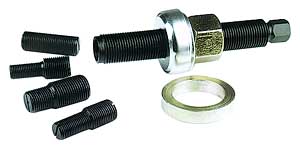
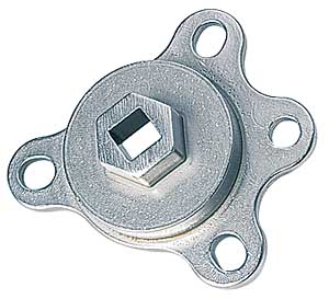
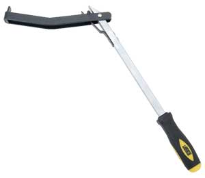
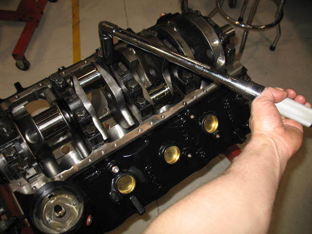
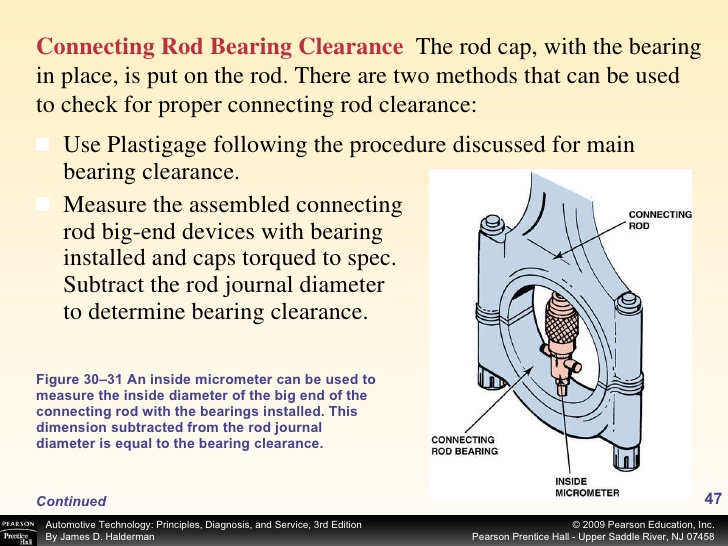
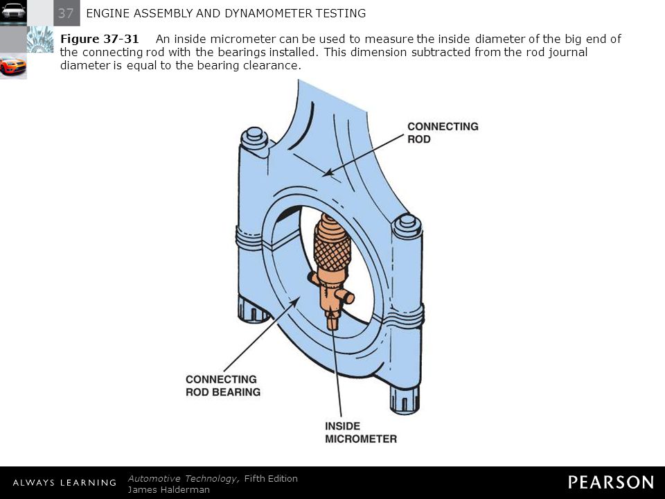
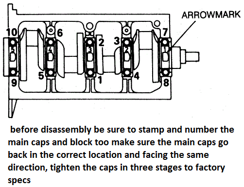
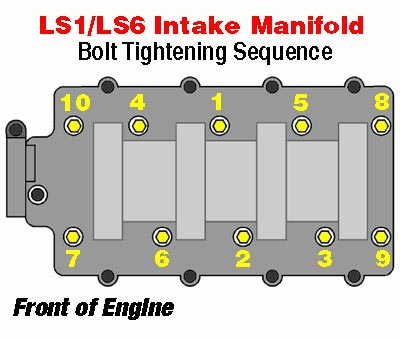
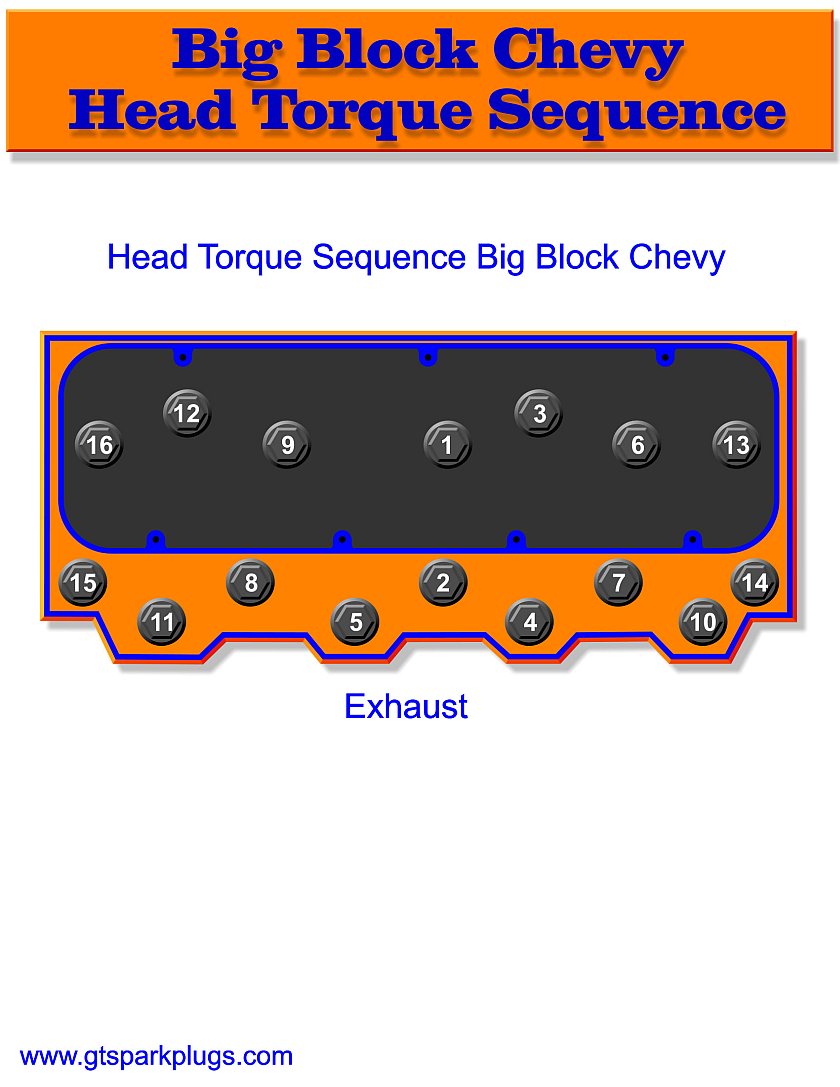
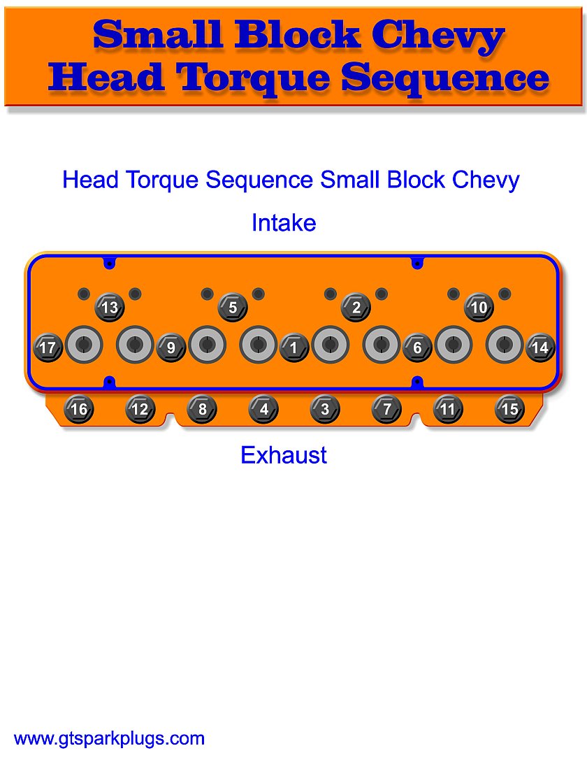
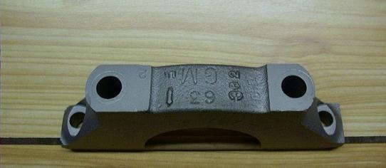
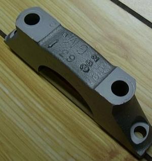
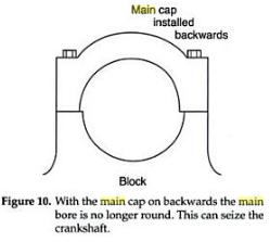
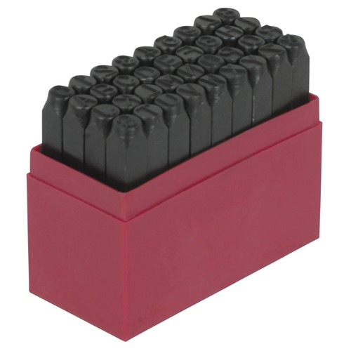
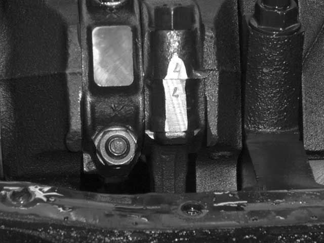
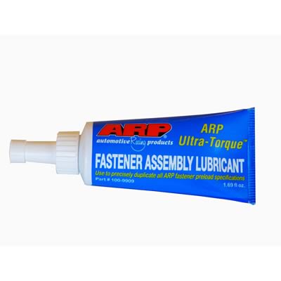


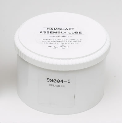
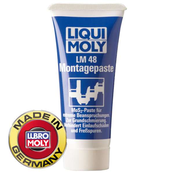

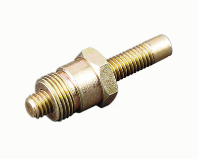
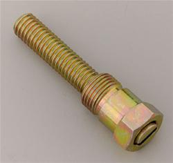
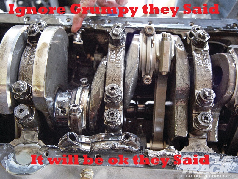
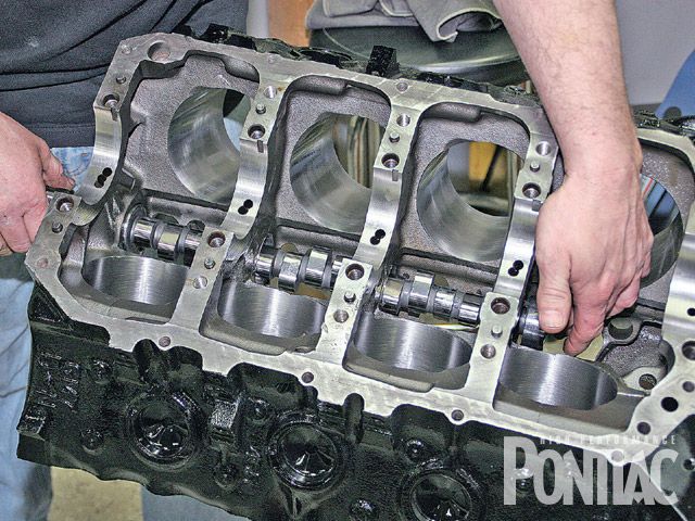
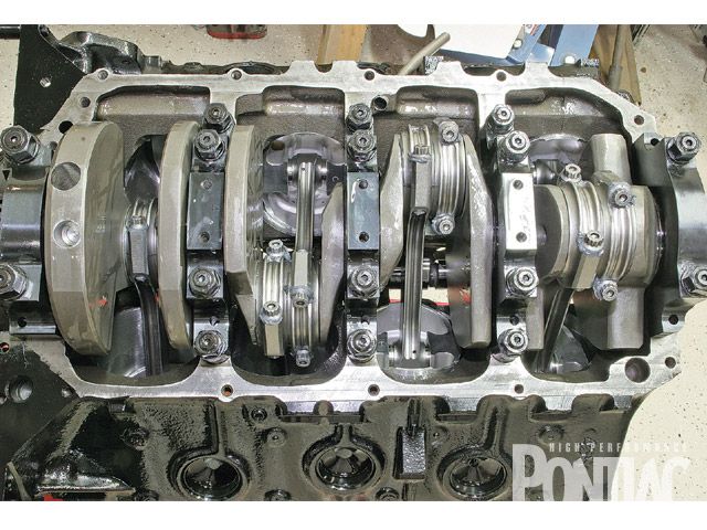
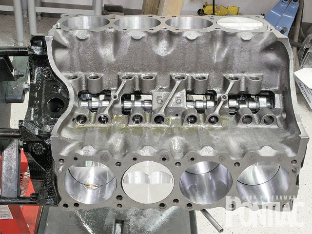
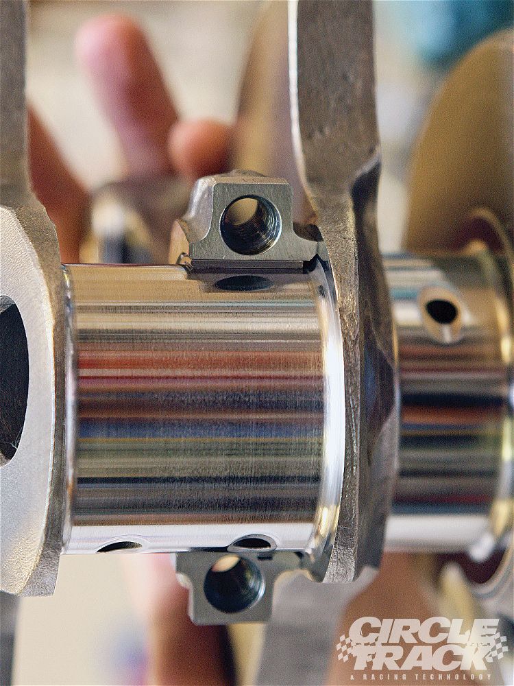
 12/13
12/13

