ring gapping and basic piston ring info YOULL NEED

Building a 1984 Buick Grand National V6 engine today Grumpy.
Starting.
File fit tge rings.
Forged CP Carillo pistons.
 
the first few rule's of GRUMPY'S engine assembly

(1) THINK THINGS THROUGH CAREFULLY ,
WRITE DOWN A LIST OF COMPONENTS ,

MAKE DARN SURE THE LIST IS COMPATIBLE WITH,
and AT LEAST SEMI-REASONABLY PRICED WITHIN YOUR BUDGET.

FOR WHAT YOU INTEND TO BUILD AND RESEARCH THE RELATED MACHINE WORK,
RESEARCH CAREFULLY THE COMPONENT INSTALLATION AND INTENDED USE ,
AND POWER BAND THE PARTS WILL REQUIRE

AND FIND AN EXPERIENCED MENTOR.

(2) if in doubt, about how to do anything, on an engine, do some detailed research,
find and compare at least 3-5 valid trust worthy sources info,
read the instructions over again, several time's very carefully
and if available watch several related videos.

(3) if any component will not easily function as designed or requires a good bit of physical force to install ,
or your not 100% sure your doing something CORRECTLY

STOP, FIND OUT EXACTLY HOW THE PARTS SUPPOSED TO FIT AND FUNCTION,& WHY! YOUR HAVING PROBLEMS
theres a reason, and you better verify your clearances are correct , and your following the instructions before you proceed.

(4) never assume the parts you purchased can be used without carefully , cleaning them prior too,
checking the physical condition, verifying clearances and using the correct sealant, lubricants etc.


(5) the quality of a component is generally at least loosely related to the cost to produce it,

and the amount of detailed research and quality machine work that went into its production.
if you got a significant reduced price, theres typically a reason.
it might simply be because a new improved part superseded the one you purchased,
but it might be a far lower quality imported clone with lower quality materials and machine work.
its the purchasers responsibility to research quality.

(6) if you did not do the work personally or at least take the effort to verify it was done correctly and personally verify clearances

ITS almost a sure thing that it was NOT done , correctly, and yes that mandates you fully understand what your looking at,
and how the components are supposed to function and have high quality precision measuring tools.

(7) ITS ALMOST ALWAYS FASTER AND LESS EXPENSIVE , AND PRODUCES BETTER RESULTS IF YOU,

BUY FEWER HIGH QUALITY PARTS & DO THINGS CORRECTLY THE FIRST TIME


I,VE USED ONE OF THESE ON MOST ENGINES

https://www.summitracing.com/parts/pro-66785/overview/
pro-66785_cp.jpg


no one has mastered all the skills and going back over even rather common assembly skills and looking for tips on how to improve existing procedures seldom hurts.
as time progresses, theres always on-going documented testing, and in many cases the old established way of doing things has proven to be less than ideal as newer and more detailed testing proves.
I well remember the advice in the later 1960s to keep end gaps on upper piston rings in the .004-.005 per inch of bore diameter, and secondary compression rings , to a tighter .04 max per inch of bore diam, as they experience less heat related expansion, the gaps could be tighter, well testing over the last 40-50 years has proven that approach to be less than idea, a looser .005-.006 second compression ring end gap is now been rather conclusively proven to work a bit better as it tends to lower and trapped combustion pressure, that could reduce the top rings bore seal.


rfig1.jpg


a dremel tool comes in very handy, it takes a great deal of patience, and caution and a good understanding of what your trying too accomplish , plus constant checking, but a dremel tool can be used, to gap rings
drem.png

when I started building engines I purchased on of these hand crank, tools,
I rapidly found it had issues in keeping the ring end gaps parallel,
I found a carefully used DREMEL TOOL with cut off wheels and careful measuring to be a reliable route you can use:like:

obviously measure very carefully and polish off LESS on the ring end gaps than you think , you need too,
and re-measure carefully and repeat, try to match the chart recommended end gaps
if your end gaps a tiny bit too large its no major issue ,but read and pay attention too the charts and work carefully


https://www.summitracing.com/parts/...MIpuDs0eDf9AIVGIiGCh3VKQvDEAQYAiABEgK8fPD_BwE
sum-906795_gk_xl.jpg


proform sells a power upgrade tool,
71pifkLVPfL._AC_SL1500_.jpg


now I work mostly on BBC engines and I built a custom ring square tool , out of cheap and easy to find PVC plumbing pipe adapters, (look at the pictures, rick posted,)remember it does not need to be a perfect bore diam. match too square the rings , but of course it must fit down the bore, too use when gapping rings,and on the big block engines you can build and use a custom tool like this without reducing the diam., but Rick went the extra step and built a very similar tool for his SBC projects engine

index.php


index.php


index.php


used carefully, and with some experience,
a dremel tool cut-off wheel can do a decent job at cutting ring end gaps
read thru these related threads, posted below, youll find a good deal of info, on installing pistons and rings.

be damn sure you verify the rings are installed in the correct location , with the correct clearances, bore surface finish,with the correct part,and the correct side of the ring facing the top of the piston
but like you stated I find its a bit odd that I find most machine shops are instantly able to quote the cost to "TORQUE PLATE HONE" several of the less popular engines like the pontiac, olds, AMC caddy, and early hemis etc. yet they don,t own the required TORQUE PLATE, and in some cases I don,t think they care or want to discuss that minor technicality
(years ago the thinking was that because the second rings did not endure the same high temperatures as the top ring the second lower ring could have less gap as it would expand less from heat, modern thinking resulting from testing shows the second ring should have a slightly wider end gap to prevent the stop ring from loosing its seal pressure and developing RING FLUTTER at higher rpms, the problem is that "higher rpms" differ with every combo built)
rings6.jpg

bores must be honed with a deck torque plate to simulate the stress of a installed cylinder head stress , the torqued bolts exert on the bore walls, the torque plate induces and duplicates that stress so that the bore walls will be pulled into the same relationship when you hone the walls concentric, rings won,t seal correctly in a non concentric bore
rings5.jpg

DSC02897.jpg


gaps must be correct for the application
RINGS MUST BE MEASURED WHILE SQUARE IN THE BORE< A RING SQUARE TOOL HELPS, I USUALLY PLACE THEM ABOUT 1" DOWN THE BORE THEN MEASURE END GAP, see later in the thread for how to make a good but dirt cheap ring square tool
RingEndGapNotParalla01.jpg

ring ends must be, correctly gaped, cut parallel and de-burred before installation
pistondiam.jpg

ringsealw2a.jpg

ringgr.png
1712333219168.png

pistonporty2.png

pistonporty.jpg

pistonporty1.png


gpass1.jpg

http://www.superstreetonline.com/how-to/engine/impp-1110-piston-anatomy-tech-knowledge/

https://goodson.com/products/gas-porting-tools

these tools come in various ring sizes ,(but the various piston diameters are not as critical as ring width, it should be obvious that you MUST USE the tool that places the drilled gas port at the correct place in the upper ring groove roof and you damn sure better not drill deeper than the rear edge of the ring groove or youll destroy the piston
gpass2.jpg

gpass3.jpg


while these professional ring filing tools ,(LINKED BELOW) would be great to have on hand,
during your engine assembly
, the price makes owning one as a hobbyist unlikely
early in this thread theres pictures and links to the manual piston ring filers
and if your very careful you can use a cut-off wheel on a dremel tool


yes as always theres cheap,functional, and theres expensive precision ring filers

NONE OF THESE TOOLS BELOW ARE CHEAP< BUT THEY ARE DECENT TOOLS
http://www.abs-products.com/specialty-t ... nder.shtml
ABS_PISTON_RING_GRINDER_480.jpg


checkringgaps.jpg


Home » EN » How to Use a Cylinder Bore Gauge To Measure Cylinder Block


How to Use a Cylinder Bore Gauge To Measure Cylinder Block

Why engine can perform a rotation outpu ? it because the engine generating power from a combustion. The power of combustion pushing down the piston. But the movement of piston must produce a friction between the cylinder and the piston ring. In a long time, this friction will cause wear between the two components. That's why older engine have less power complaints with low compression pressure.
If the cylinder is worn out, it means the power is also hampered. So it needs to be over size or replacing this one. But to know whether the engine cylinder is still feasible or not, we need to make measurements. It will calculating the size of the cylinders and engine block wear out. So how to step, consider how measure cylinder block using cylinder bore gauge below.
Differences Tautness And Wear out
Before we go any further, let's understand the meaning of these two words. Tranquility and innovation have different meanings.


    • Tautness, is a cylindrical wear when viewed from the side of the cylinder. This form of is tapered because there is a different size of the lower and upper cylinders. This difference will show a great tune.
    • Wear out, is a form of engine cylinder wear when viewed from the top. The normal cylinder, will definitely be a perfect circle when viewed from above. But when it form more oval, then it might be a signal that showing the cylinder wear out.
How To Measure Cylinder Block Diameter ?
To measure the diameter of engine block, we need a special tool called Cylinder Bore Gauge. This tool can measure the diameter of the cylinder with precision reaching 0.01 mm. But before making a measurement, we need to make some setting on this tool.
cylinder bore gauge component and function
PicsArt_03-11-01.53.55.jpg


    • Dial gauge. This component will show the size scale with units of milli meters.
    • Lock position. This component serves to hold the dial gauge remain silent when bore gauge is used.
    • Grip. This component serves as a handle when applying a bore gauge.
    • Replacement rod. Component of a rod of varying length to measure many cylinders having different diameters.
    • Replacement washer. Similar to replacement rod, but replacement washer has a small thickness. Ranges 0.5 mm.
    • Measuring point. In the form of a bulge, when pressed it will move the needle of dial gauge.
1. Steps to adjust the bore gauge cylinder.
To make the adjustment, we need to know normal specification of cylinder diameter, you can find this specification on the service literarure each car or you need to measure directly using vernier caliper. But you need to know that this measurement is not a real measurement, because we just need a scale to set the right replacement rod.
If you already know the diameter of cylinder then, continue to assemble the cylinder bore gauge. Start with installing the right replacement rod on the bore gauge. Suppose the diameter of the cylinder is 62.05 mm. Then we choose a replacement rod with a length of 60 mm plus replacement washer with a thickness of 3 mm. So a total length is 63.00 mm.
Why is it higher?

Advertisement

Because we will measure a wear. Components that experience wear and tear must have an enlarged diameter. If we choose the replacement rod of the same or smaller than the diameter of the cylinder, then the measuring point can not be depressed when taking the measurement.
PicsArt_03-11-01.58.07.jpg

Once installed, set the dial gauge to zero using the micrometer. Position outer micrometer at size 62,05 mm, put the cylinder bore gauge (replacement rod parts) on timble micrometer. Then the measuring point will move and the dial gauge needle moves. Set the dial gauge scale to zero position on the dial gauge needle.
2. Step to Measure Cylinder block diameter.
Perform measurements inside the cylinder. There are three measurement positions of each cylinder that is on the X and Y axes of each upper, middle and lower positions. The X axis is the line that intersects the engine horizontally. While the Y axis is the line that cuts the machine vertically or elongated. So total, there are six measurement each cylinder.
PicsArt_03-11-01.48.57.jpg

How to measure it ? input the cylinder bore gauge into the cylinder. Then, shake this tool left and right while watching the dial dial indicator. We need to pay attention to the farthest point of moving needles. Because this point will show the difference in diameter of the cylinder with a standard diameter. Perform this measurement at each position of each cylinder.
To calculate wear out, we need to find the difference between the measurement of X axist and Y axis at each position. While the tautness, we can know by finding the difference in measurement of the top and bottom diameters on one axis.
PicsArt_03-11-01.44.55.jpg

Another way of measuring the diameter of the cylinder.
The step above is the correct procedure to measuring size of cylinder block. However, in its application sometimes encountered several constraints such as measurement results that are smaller than the standard. It could happen because each engine has a different diameter even made in the same factory. For that there is simple way that many technicians use to measure engine block diameter.
The first step, we need to see the standar diameter on technical specification. Remember, we need to know the right specification and dont measure with vernier caliper. Why, bceause this data will be our benchmark to get the wear out. Once you see the right standar diameter then assembly the bore gauge and, make direct adjustments inside the cylinder.
Like the above procedure, there is six position each cylinder but for first enter the cylinder bore gauge to the bottom position of cylinder to set the bore gauge. In this case, we are based that the bottom position is an area that does not experience friction with piston rings. So the diameter is still standard.
Continue to move the bore gauge right and left. Notice the farthest point of the dial gauge needle. Position the dial gauge scale to zero position exactly on the needle moving to the furthest point.
Furthermore, we directly conduct the measurement of the diameter of the cylinder in the six positions as described above. In this case, to know the cylinder diameter you should looking for the difference between standar diameter as benchmark and the result of measurement.
Once you find the correct diameter, you can calculate the wear out and tautness of cylinder. From this data, you can conclude the condition of engine block.

Similarly, guidance on how to use cylinder bore gauge to measure the diameter cylinder. Aside from the cylinder's sharpness and wear out, diseases of the engine can also be caused by non-standard pistons. Check how the piston check to be more clear. Hope can be useful.
PRF-812DWz.jpg

https://goodson.com/products/piston-ring-filer


812dw.jpg

https://www.summitracing.com/parts/tsr-prf-812dw
$700
New
http://honingplates.com/index.php?main_page=product_info&products_id=28

http://honingplates.com/index.php?main_page=product_info&products_id=29


http://garage.grumpysperformance.co...piston-to-bore-clearance-on-your-block.14251/

http://garage.grumpysperformance.com/index.php?threads/maximizing-piston-to-bore-ring-seal.3897/
 
Last edited:
This is a GREAT picture showing the benefits of using a deck torque plate. Thanks Grumpy.

rings6.jpg

now I work mostly on BBC engines and I built a custom ring square tool , out of cheap and easy to find PVC plumbing pipe adapters, (look at the pictures, rick posted,)remember it does not need to be a perfect bore diam. match too square the rings , but of course it must fit down the bore, too use when gapping rings,and on the big block engines you can build and use a custom tool like this without reducing the diam., but Rick went the extra step and built a very similar tool for his SBC projects engine

index.php

index.php


index.php

index.php

index.php


ringapl1.jpg

ringgapl1.jpg

ringgapl2.png

ringgapl3.jpg

https://www.hastingsmfg.com/ServiceTips/cylinder_bore_refinishing.htm

http://www.enginebuildermag.com/2004/05/cylinder-bore-refinishing/

http://www.enginebuildermag.com/2000/09/cylinder-bore-surface-finishes/

http://www.aa1car.com/library/honing98.htm

http://www.aa1car.com/library/ring_end_gap.htm

http://www.enginebuildermag.com/2002/11/the-smooth-science-of-cylinder-honing/


Last edited by a moderator:
I want an electric motor powered ring filer Grumpy.
Built alot of engines in that race shop last year.
I did all rings with a hand crank Childs & Albert Ring Filer.

Do my own later this year.
Ling time coming.
 
http://www.enginebuildermag.com/2018/05/how-to-break-in-your-piston-rings-the-right-way/
How to Break-In Your Piston Rings, The Right Way!
Print Email
JEPistons.jpg
SPONSORED BY
JE Pistons


Ring-00.jpg


Captain Kirk in the now-classic Star Trek TV series was constantly badgering poor Scotty for “More power!” That’s what everybody wants. More power! One way to ensure the horsepower built into your engine is achieved is to seize every opportunity to seal that cylinder pressure on the push side of the pistons.

A great way to take full advantage of the 21st Century engineering that goes into piston rings is optimize the break-in / ring seating procedure. This goes way beyond just choosing the right break-in oil, although that’s an excellent start. As we’ll see, the process is somewhat specific and less than rewarding if you screw it up!

RING-01.jpg

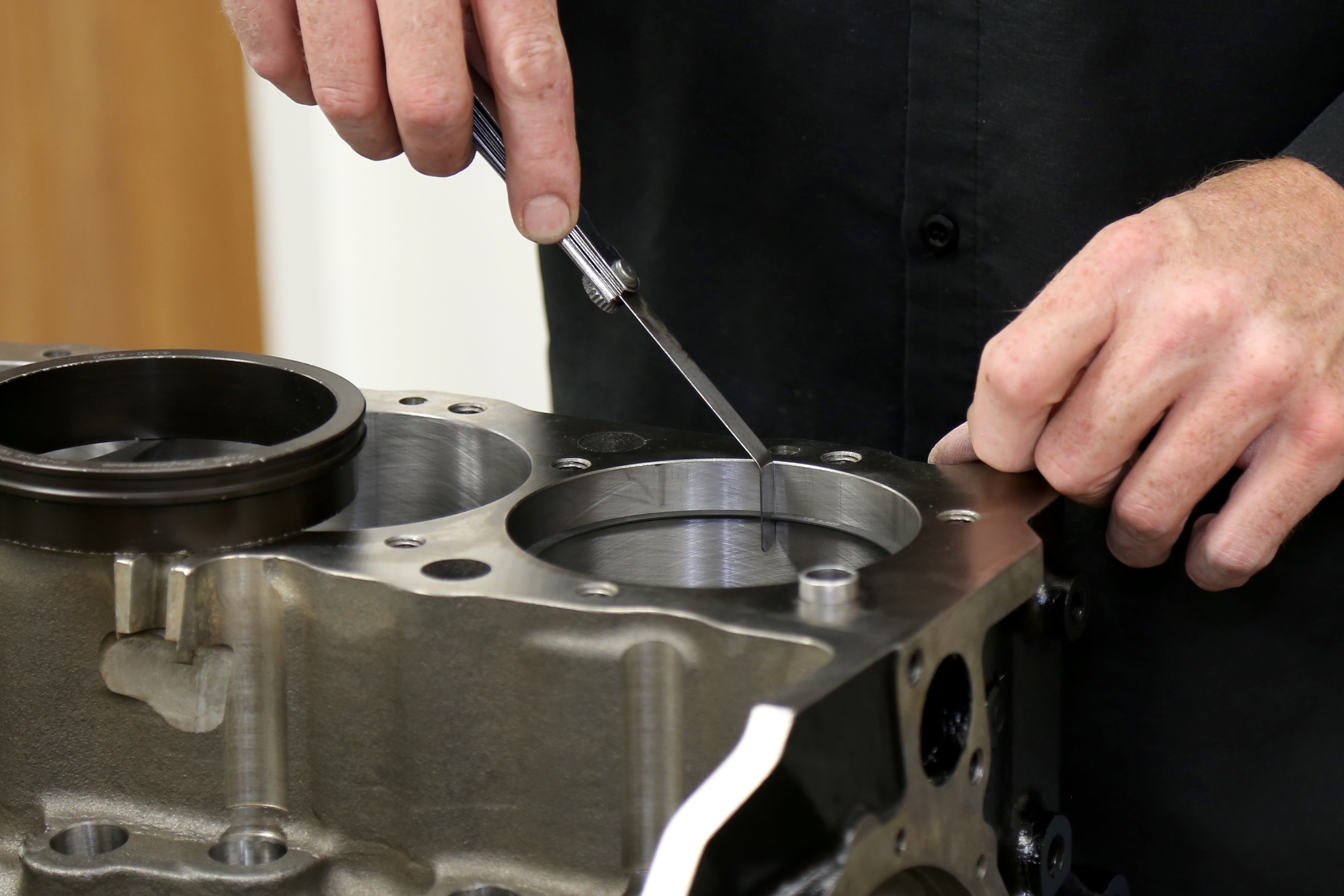
Bore finish will have a lasting effect on both how well the rings break in and the extent that they seal both cylinder pressure and keep oil out of the chamber.
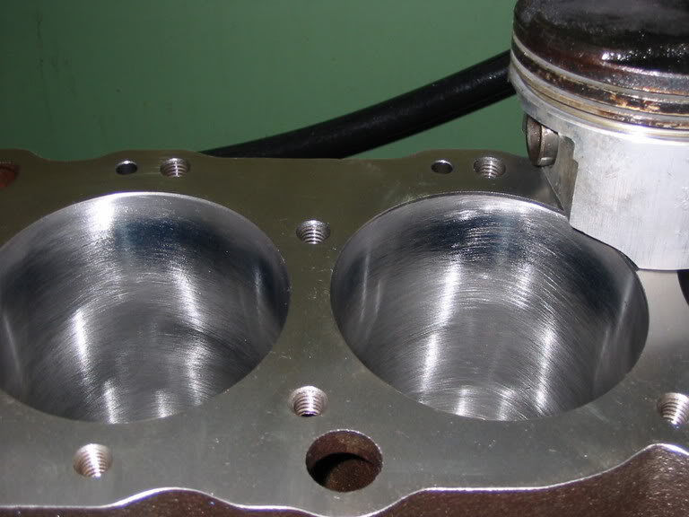
Idealizing ring seal starts with proper cylinder honing. It’s beyond the focus of this story to get into specific procedures, but a proper torque plate honing with a 45 degree included honing angle is certainly moving in the right direction. That included angle helps both retain oil and also promotes ring movement within the grooves, which is important to maintain sealing.

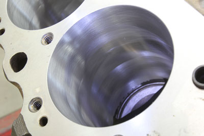
The somewhat rough surface of a freshly-honed cylinder is established in part to promote a wear pattern between it and the ring face. In order to do this, the rings will remove the microscopic peaks created by the honing process. Creating the proper height of these peaks and the depth of the valleys will significantly improve the potential for ring seal. Lubrication is another critical element in this process but oil can only achieve its intended goals of lubrication and improving ring seal when the other conditions are also met.

When assembling the engine, JE recommends using either engine oil or a light machine oil for the cylinder wall and rings. This lubricant will be present only for the initial revolutions until the engine starts. Highly viscous or sticky engine assembly lubes should be avoided around the ring package.

RING-02.jpg

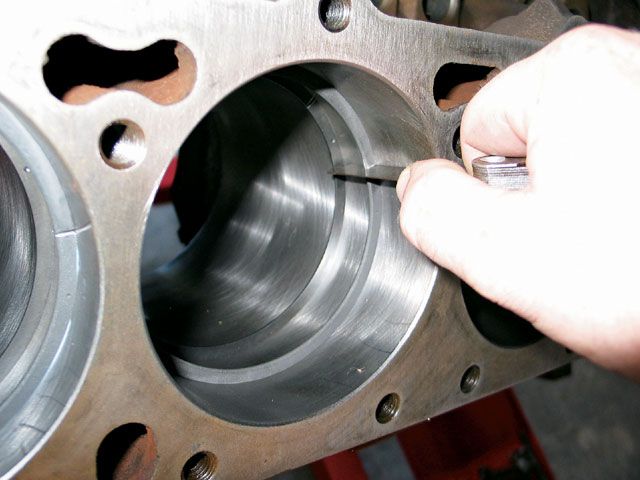
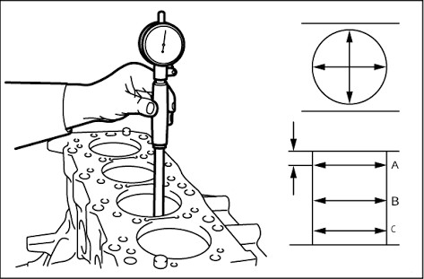
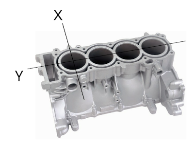
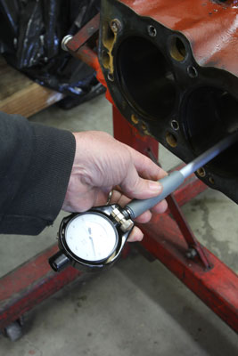
Cylinder wall taper or out-of-round makes the ring’s task of sealing and break-in much more difficult. This places a premium on proper honing technique and finish.
This brings us to how the engine should be run after initial startup. The ideal combination is to tune the engine so that it starts on the first or second revolution. For carbureted engines, this means pre-filling the fuel bowls and accurately setting the initial timing. As soon as the engine starts, immediately bring it up to an above-idle speed. According to JE’s Senior Technical Account Manager Alan Stevenson, “You don’t want to break-in an engine at idle. You want to keep the rpm above 1,500 and vary the speed continuously for about the first 20 minutes.” After bringing the engine up to normalized coolant and oil temperature, put the engine under load. The cylinder pressure from 50 to 75 percent and eventually to 100 percent load will place additional pressure on the back side of the rings which will quickly establish the proper wear pattern for seating. With today’s rings, especially moly-faced versions, this can be achieved in a very short period of time and certainly within 20 to 30 miles of street driving. In WOT dyno testing, likely the rings are seated by the end of the first few runs.

RING-03.jpg

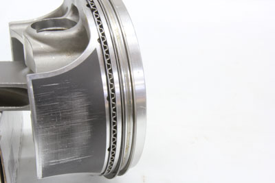
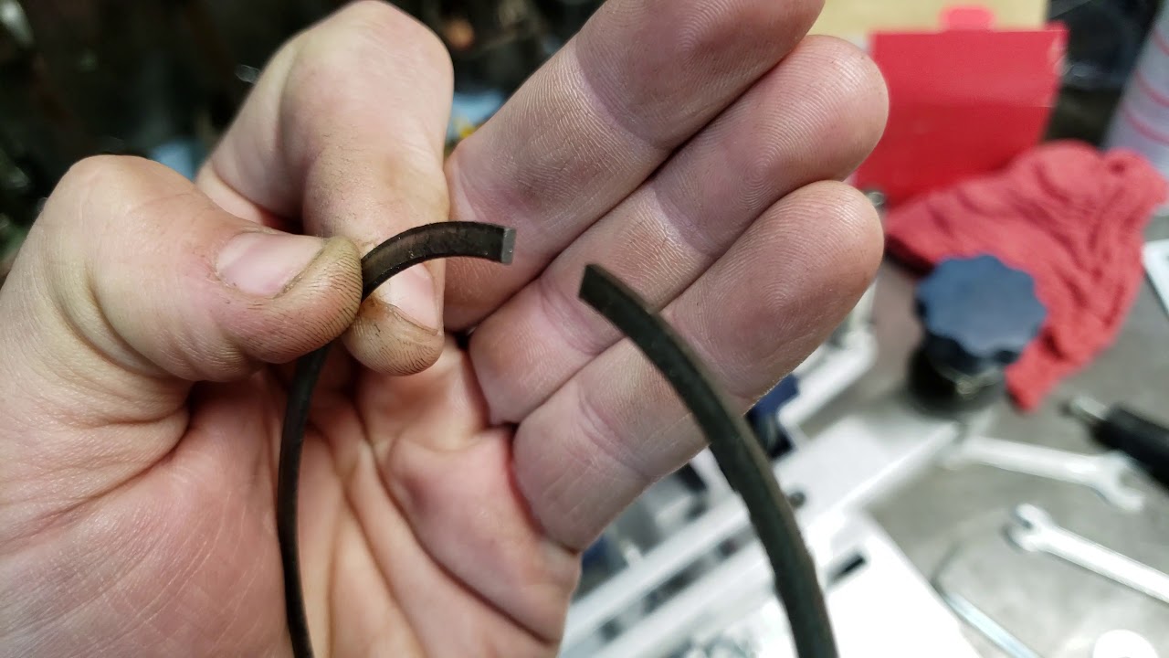
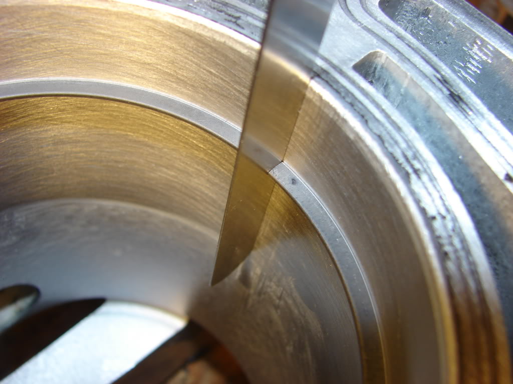
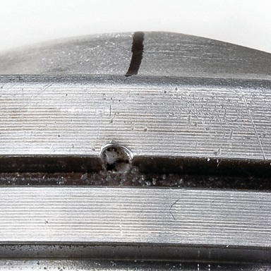
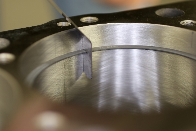
Note how the second ring is worn only on the bottom half – which is where this oil control ring should wear. The top ring wear is difficult to see but is actually only contacting in the center of the moly inlay finish.
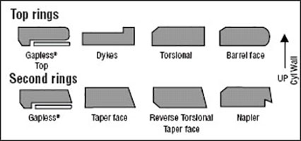
Engine enthusiasts are often quick to condemn a ring as “not seated” because the wear pattern is not spread across the full face of the ring. This is unfortunately an incorrect assumption. Nearly all top rings offer a barrel face where only a portion of the ring at the widest point is actually in contact with the cylinder wall. So only a small part of the ring will exhibit wear. A top or second ring that exhibits full face contact should be considered worn out. Proper ring performance and sealing is based on the rings sliding across a coating of oil between the ring and the cylinder wall in much the same fashion as a crankshaft journal rides on a thin film of oil between it and the bearing.

Glazing is a term often used when discussing a cylinder that is not broken in properly. This often occurs after an engine has been run at idle or very light load for a sufficient enough time. This creates a case where oxidized oil has collected on the cylinder walls and created a somewhat shiny surface coating that has completely filled in the peaks and valleys of the honing process. As a visual reference, imagine the microscopic cross-section of a freshly honed cylinder wall as similar in appearance to the side view of a hack saw blade with multiple peaks and valleys. Now imagine looking at a used hack saw blade where the teeth have worn nearly smooth. That’s what a glazed cylinder wall would present to the rings.

RING-04.jpg

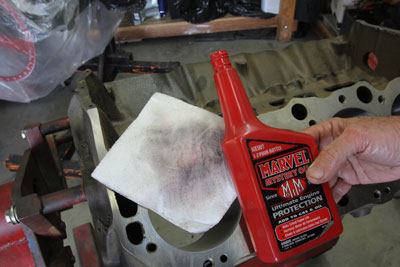
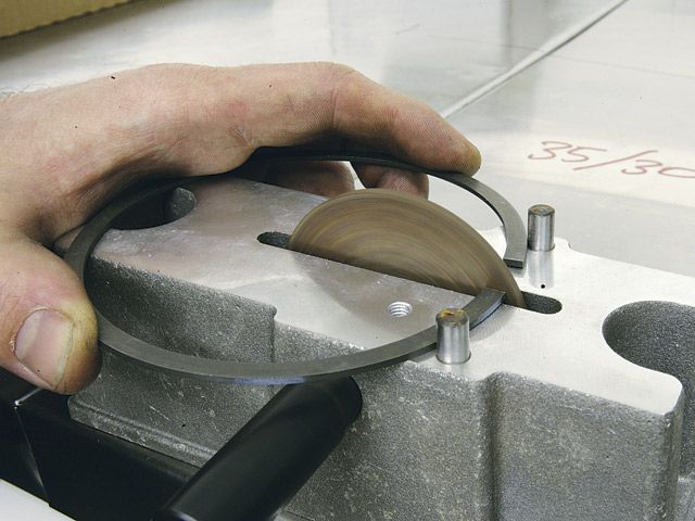
Establishing ring seal begins with proper assembly and that means cleaning the cylinder walls. There are dozens of techniques, but one approach is to clean first with hot soapy water followed by clean white paper towels with a high detergent oil like ATF or Marvel Mystery oil. This towel still shows grit after four earlier cleaning passes. Keep going until each bore is clean.
With the peaks and valleys filled in, the glaze creates an extremely smooth surface, making oil control very difficult. The net result is excessive oil usage. Sometimes this glaze will exhibit excessive oil consumption with or without the presence of the classic blue oil smoke. A quick way to evaluate above-normal oil usage is to pull the spark plugs and look for oil on the threads of the spark plugs. This is a common warning sign of a loss of oil control.

If you suspect the rings have not seated, sometimes this can be addressed with a top-end cleaner. This does not mean dumping a couple of teaspoons of Bon-Ami cleanser down the intake. While laughable, that flathead era recommendation has somehow survived the electronic age. But reputable top end cleaners have been used with some success.

Glazing can also be traced to an over-exuberant choice in break-in oil. There are probably almost as many choices for boutique engine oil as the Kardashian girls have in shoes. According to Stevenson, selecting a break-in oil should focus first on ensuring the oil is compatible with the camshaft. A flat-tappet cam will require a greater concentration of high pressure lubricants like zinc dialkyld-dithiophosphate (ZDDP) compared to pistons rings so selecting a break-in oil should prioritize in that fashion. There are no industry ZDDP level standards for break-in oils. For a high performance, non-API break-in oil, a common concentration would in the neighborhood of 1,000 to 1,500 parts-per-million (ppm).

RING-05.jpg

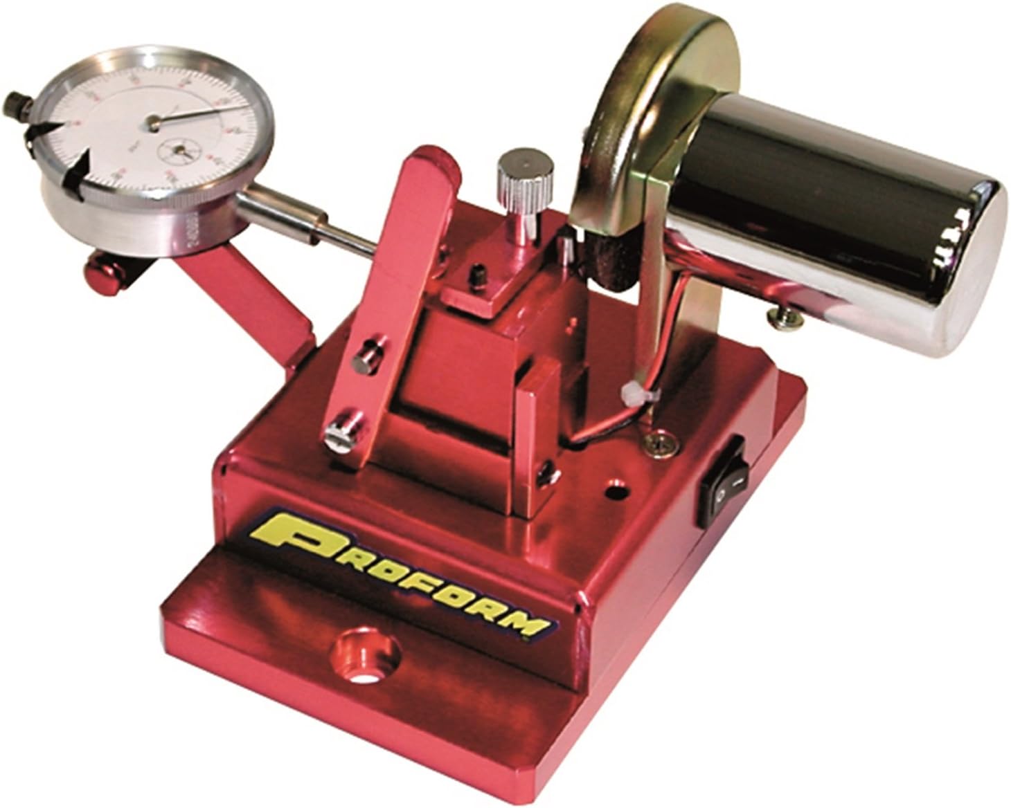
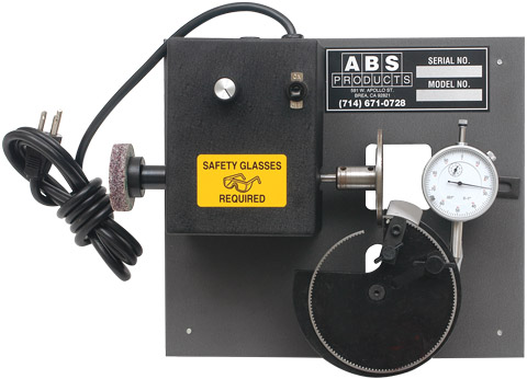
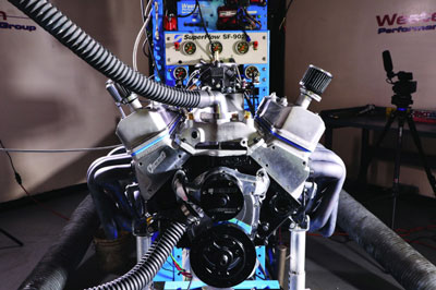
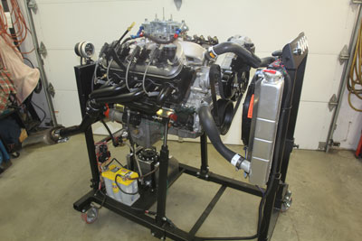
Engine test stands are great for checking for runs, drips, and errors but should not be used to break-in rings. Proper ring break-in requires a load be placed on the engine as soon as possible.
Problems can occur when the “more is better” theory is applied and ZDDP concentrations radically exceed the above-mentioned levels. An excessive ZDDP level accompanied by low levels of detergents is a poor combination. ZDDP tends to molecularly bond with metal while detergents work to strip these same additives from areas like the cylinder wall. If excessive ZDDP levels are used, this can cause cylinder wall glazing and loss of oil control.

Of course, the rest of the engine configuration must be properly prepared as well. A common cause of ring seal failure is created if the engine is run with an overly-rich air-fuel ratio. Carburetors are often accused of this malady, but a poorly-tuned EFI system running at 10:1 air-fuel ratio can do an equal amount of damage. Excessively rich air-fuel ratios allow raw fuel to strip oil off the cylinder wall, minimizing the lubrication at the precise time that the rings and cylinder walls need it the most. Part of a rich mixture mistake is the widely-maintained misconception that lean idle air-fuel ratios cause an engine to run hotter. The reality is that lean idle mixtures minimize temperature gain as less heat is exposed to the cooling system because less fuel is combusted.

Ring-06.jpg

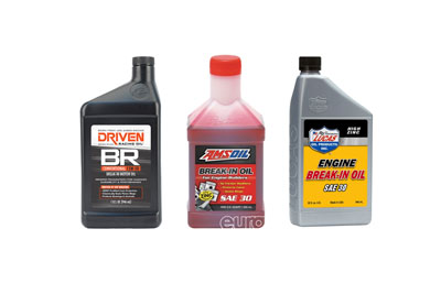
Choosing the correct break-in oil is pivotal for proper engine break-in. Almost every quality oil company offers a break-in oil that dispenses with some of the additives that can inhibit the break-in process.
If an engine is allowed to idle in an overly-rich condition for as little as 30 minutes, this can cause sufficient cylinder wall damage where the wall may exhibit a dull, dark grey color. If this occurs, the engine will likely require complete disassembly and fresh honing.

Break-in oil should also only be used for initial engine run-in and then changed along with the filter and replaced with the engine oil you intend to run. On a street engine, this would mean less than 100 miles. Changing the break-in oil removes the impurities that will be present in the oil from the break-in period. This is especially true with race engines that use less restrictive filters. JE also recommends avoiding synthetics during break-in in order to take full advantage of establishing wear patterns. Synthetics sometimes can do too good a job of reducing friction so that the rings cannot seat properly.

ring-07.jpg

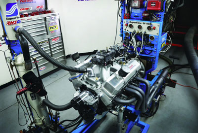
When breaking in an engine, it is important to vary the load on the engine. A dynamometer often has a preset break-in mode that varies load and engine RPM.
What should also be avoided is custom blending your own additive package either for break-in or long-term operation. Lubrication engineering is a complex game of blending a base oil and additive package brew that is intended for a specific application. So choosing the right lubricant is a great way to ensure your new engine starts life in the best way possible.

Piston ring break-in and optimized sealing isn’t difficult if you pay attention to the important initial steps on the way toward proper care and feeding of a high-performance engine.

This article was sponsored by JE Pistons. For more information, please visit our website at www.jepistons.com
 
Last edited:
http://www.onallcylinders.com/2016/...ith-piston-ring-thickness-and-why-thin-is-in/

Posted by Jeff Smith on January 15, 2016 at 10:18 am
I’ve heard that late model engines now run much thinner rings than the older production engines. Are these thinner rings just there to improve fuel mileage or is there a power advantage with these new rings? I’m about to rebuild my small-block Ford and I’d be willing to try something newer if it’s better. Thanks

F.R.

Jeff Smith:
According to the old Hollywood line – you can’t be too rich or too thin. In the case of piston rings – those two items are pretty closely tied together. Thinner is definitely better but that reduced girth will also cost you some coin. But that’s way too simplified an answer.

Let’s jump into this area with some interesting details.

In the muscle car days, the standard ring package was a 5/64-inch top and second ring with a 3/16 oil ring set. This dimension refers to the ring’s thickness as viewed from the side of the piston. This 5/64-inch thickness (0.078-inch) required a significant amount of load pushing outward to ensure an adequate seal. This load – called radial tension – also produced a significant amount of friction. The most friction in any three-ring piston package is created by the oil ring but the combination of all three rings in this width is significant.

Moving closer to the 21st Century, OE engineers revised these specs and realized that a thinner ring package would help reduce friction and improve better fuel economy. The GM LS engine family, for example, came with a 1.5mm/1.5mm/3.0mm ring package. This equates to 0.058/0.058/0.118 compared to the older thicknesses of 0.078/0.078/0.187. This is a 25-percent reduction in ring thickness. As the ring becomes thinner, the amount of radial (outward) tension required to seal it to the cylinder wall is reduced. This occurs because as we reduce the total surface area of the ring touching the cylinder wall, the radial tension can be reduced to produce the same amount of load on the ring. Think of it this way. A woman can easily walk across wet ground with normal, flat shoes with lots of surface area. But if she attempts to walk on soft ground in a pair of spike high heels, that tiny area under her heel will sink right into the soft ground. Her weight hasn’t changed, but that spike high heel concentrates that same weight (load) in a very small area. So if we think of a thin ring as that spiked high heel, it now requires far less outward load (radial tension) on the ring to present the same amount of sealing load against the cylinder wall.

By reducing the radial tension on a thin ring, this also reduces the friction created as that ring slides up and down the cylinder wall. This occurs with all three rings, including the oil control rings. So now we’ve just added a slight amount of horsepower just by reducing friction. But the news gets better. Thinner rings also tend to seal better to the cylinder wall, which means blow-by past the rings is reduced and more cylinder pressure is retained above the pistons to make more power.

So for performance engines, the industry has been slowly migrating toward thinner rings. Not all that long ago, the drag racing standard performance ring was a 0.043-inch wide Dykes ring with a step that improved ring loading. That equates to roughly to a 1.1mm ring. Until recently, Mahle’s performance ring package on most of its PowerPak performance forged pistons utilized a 1.5/1.5/3.0mm ring combination. The top two rings were equivalent to a 0.059-inch wide ring. But last year, Mahle introduced a new ring piston and ring package that now trims the rings to 1.0/1.0/2.0mm dimensions (0.039/0.039/0.078-inch). It’s clear that the movement is toward increasingly thinner ring packages.

Total Seal seems to be the company that is leading the way with an entire line of thin ring packages with top ring offerings in their Ultra-Thin Advanced Profile series with 0.9mm top and second rings with a 2mm oil ring. This 0.9mm equate to 0.035-inch thick top and second rings with the 2mm oil ring at 0.078-inch. According to Total Seal, replacing a typical 1/16/1/16/3/16-inch ring package with this Ultra-Thin 0.9/0.9/2mm combination would reduce ring friction by 90 percent!

You might also think that using these ultra-thin rings for example might demand a custom-built piston. But Total Seal’s Keith Jones says that they also offer ring spacers that allow the use of a thin ring package in pistons with wider ring grooves. As an example, you could go with a 0.043-inch wide top and second ring with spacers to fit within a typical 5/64-inch ring groove piston. The original reason for this was to accommodate NHRA Stock Eliminator engine builders were forced by the rules to use stock replacement pistons. The rules only governed the piston dimensions, not the rings. Enterprising racers began demanding spacers to allow them to run ultra-thin rings in these stock ring grooves.

If you take this idea a step further, long-stroke engines will especially benefit from this reduced friction since the longer the stroke, the father the piston must travel. This additional travel creates its own friction but you can mitigate that somewhat by using thinner rings.

As you might imagine, none of this new thin-ring technology is inexpensive. A typical Total Seal Classic 1/16-inch ring set from Summit Racing for a 4.030-inch bore for example runs around $112 for the complete set. Step up to a set of 0.043-inch rings for the same bore size with a Total Seal Gapless Second ring and the price jumps to around $380 for a set of rings. Spacers will bump that even further –potentially placing a set of rings near $500. Compare that to a stock replacement set of 5/64-inch iron rings for a small-block Chevy at $21 and you can see that technology comes with a steep price.

We also looked into a set of Mahle PowerPak pistons and rings using the 1.5/1.5/3.0mm ring package in a typical small-block Chevy 383 flat-top piston combination and that would run just a touch over $700 for the pistons, rings, and wrist pins. That’s just one example of how you could take advantage of this new ring technology, but there are as many different avenues as there are creative engine builders. You might want to think about taking advantage of some of this technology – the savvy engine builders are already doing exactly that.
btw that innitial resistence ,too rotation, to get the crank assembly rotating in the bearings and rings dragging accross the cylinder bore surfaces,
as the parts come up on the combined, wedge/lubricant bearing surfaces ,
when it breaks loose and spins easier, is closely related to and changes with the type of assembly lube you selected to use.
the components sellected and clearances and contact surface smoothness and consistency,
every assembly will have minor differences, as will every different lubricant, even temperature will change the results.

that's why you'll need a torque beam deflection torque wrench to check that
beam_torque_wrench.jpg


https://www.amazon.com/Presa-Drive-...ocphy=9012039&hvtargid=pla-669567243785&psc=1

good related info
http://www.hotrod.com/articles/dyno-tested-thin-piston-rings-worth-horsepower/


http://www.us.mahle.com/en/motorsports/news/get-thin-with-smaller-thinner-rings.jsp

http://www.enginebuildermag.com/2017/03/10-things-might-not-know-pistons-rings/

http://www.aamco.alldata.com/online...een_low-tension_and_ordinary_piston_rings.htm

http://www.dragzine.com/tech-stories/engine/mahles-thin-piston-ring-technology-affordable-effective/
 
Last edited:
Just my opinion this morning Grumpy.
No one has serious Drag Race intentions but You and me.
Specialized Drag Race individual items like Advanced Diametric profile rings made of Tool steel or stainless steel not needed.
Not for your 6000-6500 rpm redline street engine builds.
And entire rotating assembly prebalaced is best fit for most.
Keep the costs down.

Only guys that will spend $400-800 for a set of Race Piston Rings is you and me.
 
Grumpy I only found this web site after researching why my newly rebuilt engine,
smoked like a mosquito spray truck,
after reading these and a few related links, I have a very good idea what I did wrong,
I checked the ring end gap, but I never realized the rings have an upper and lower facing side!
Yeah I know "DUMB AS A BUCKET of ROCK's"
well, now Im forced to pull it all apart , and check it out,
but at least now I think the reasons obvious! ID bet at least ,several upper and secondary compression rings are installed incorrectly


WE ALL MAKE MISTAKES its simply part of the learning process,
If you think anyone ever learned everything they needed to know during the first engine assembly your totally WRONG!
I know I certainly made my share on a couple early engine builds!
just put it down too a LEARNING experience and check the rings proper orientation,
Check ring end gap and the bore hone and piston to bore side clearance,
check for detonation damage and valve to piston contact,
be sure you did NOT over fill the engine with oil,
if its several quarts too full that might also cause issues. etc.
and obviously check the valve guides , valve seals, and do a compression and leak down test.
Id suggest reading all the linked info on this web-site related to rings, pistons etc.
you might be amazed at the detailed info and useful tips they contain.


Every set of rings I have ever bought bought came in an individual pack with instructions on them or the box that carried them all showed which side went up on the piston. Most had a Dimple/Dot for that mark on the rings and a diagram of the oil ring installation. Some just showed which side of the ring with the bevel and whether it went up or down.

When all else fails---Read instructions first. Follow Grumpy"s linked info.
 
Last edited by a moderator:
you might be amazed at how few people read instructions over carefully
 
I looked around Last night.
Obamacare is the #1 Reason why Hotrodders & Corvette Guys are Broke in the USA.
Baby Boomers will not admit it.
They Need there Meds or will Die.

I am starting to see my generation get hit with healthcare problems and getting Bankrupted by Obama care.

I am in great physical shape yet luckily.
 

I can't get this image out of my head .......... and it has me really pissed off!
It's not the image itself, but what it represents. This is the poster child for the younger generation.
And to think that these "things" are going to have to run the country at some point. We're screwed!

CRASH POSITIONS everyone. Put your head between your legs and kiss your a$$ good-bye!
You old(er) people don't know how lucky you are to not have to see what is coming in the future.
 
I have to call BHJ yet and let them know The spacer count & seems to be a mixup in spacer heights.
Do that January 02 -03, 2019.
 
how do you find which side of a piston ring goes up

The general rule is that bevels go down and dots/top marks go up. Note, that the word “TOP” does not mean that this is a top ring! But rather, that side of the ring should face the top of the engine.


Back
Top