http://www.enginebuildermag.com/Article ... teria.aspx
http://www.circletrack.com/techarticles ... index.html
viewtopic.php?f=52&t=2782&p=7214#p7214
viewtopic.php?f=52&t=112&p=139#p139
viewtopic.php?f=52&t=324

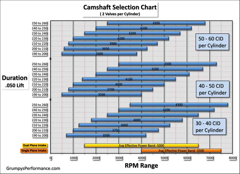
in case you don,t understand the chart, you take the engine displacement PER CYLINDER divided by the valve diam. then you use that on the chart to locate the lsa
example
lets assume youve got a 383sbc, 383/8=47.88
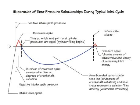
divide that by intake diam., lets say 2.02 and you get 23.7 youll see the ideal is near 105 lsa, but then you ask,WHY are most cams ground with a 110-112 LSA its because that tight lsa may maximize the peak volumetric efficiency,and peak hp/torque, it will also be far from ideal at low speed, with a lopey idle, or for emission testing or for ease of low and mid rpm ease of tuning or for sensors to read because of low rpm reversion in the intake runners.so a compromise with a wider LSA is used, sacrificing a bit of peak hp for better average drive ability and lower emissions and better mileage
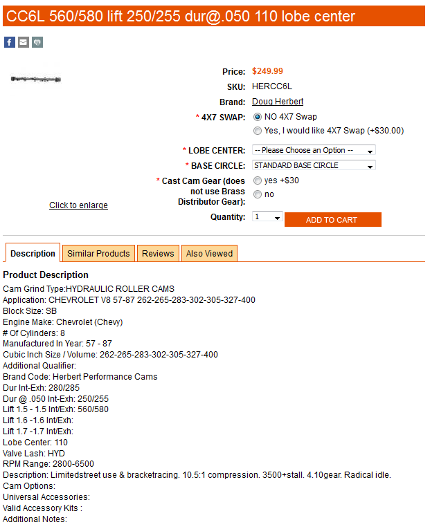
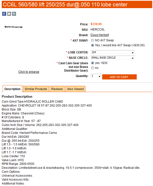
http://www.herbertcams.com/560-580-lift-250-255-dur-050-110-lobe-center/
theres some rather significant advantages in ordering a cam that closely matches the engines
requirements, and after building dozens of similar engines youll notice some trends and you may want to tweak the cam timing, this of course requires both a good understanding of what your trying to change or accomplish and what the changes you intend to make are likely to do to engine performance.
heres a cam thats rather well known for producing good power in a 10.7:1 compression 406 SBC combo.
(use mostly for racing in a light weight car like a cobra replica)
Ive built several times in the past, it really requires the following matched components
210-230cc port heads, 5" scat rods on a forged crank, a 3600-3800rpm stall converter, a 4.11:1-4.56:1 rear gear and an automatic trans that shifts at 6300rpm under full load race acceleration.
a good single plane intake like the edelbrock VIC series, an 850 cfm carb, long tube 1 3/4" headers 1.6:1 roller rockers and a rocker stud girdle
heres the came basic cam, but with a few mods that provide about 20 extra horse power, but at the cost of a noticeably rougher lope in the idle
notice the tighter LSA and its a 4/7 swap cam version on a smaller base circle
look at the chart,

Critical Cam Event Criteria
By David Vizard
I just know someone is going to ask what qualifies me to write on this subject so let’s get that out of the way up front. During a large portion of 1985 I dyno tested more than 4,000 cam and rocker combinations in three differently spec’d SB Chevys for Crane.
The following year I did a similar but larger exercise on 2.0L Pinto motors and the "A" series Mini Cooper motors for Kent Cams in England. Between 1987 and now I have done a number of similar, if somewhat smaller, exercises for other well-known cam companies including Isky and Comp Cams.
All this amounts to a stack of dyno sheets that I would estimate at over six feet high! Now that’s out of the way let’s get down to business.
None of us who are in business for ourselves has to be reminded that time is money and in the high-performance engine building business that can be a sensitive subject. Anyone intent on building a customer base understands that quality, reliability and results at a reasonable cost to the customer are the key factors toward success. The problem is, if you spend the time to do the job to your very best the customer probably can’t afford it.
The trick here is to understand where the best compromises lay. If you can get 98 percent of the results in 25-50 percent of the time then chances are you will have satisfied customers.
There are probably very few places where it is more important to strike the right compromises than in the area of cam selection and installation. Let’s set the scene here. You have a customer with a moderate budget who wants a performance street motor built and part of the deal is that it’s up to you to select the cam for the job. Without spending forever researching it, and nearly as long installing and timing it, what cam will be the best for the job? Here are some pointers that will help you make better choices in a number of areas for a better end result.
Duration
All too often, cams are selected on the basis of duration. This is not the best criterion, however. Overlap is a significantly more influential factor. The key here is not to go overboard on this.
The principle parameter dictating how much can be used is strongly influenced by the ratio of displacement relative to cylinder head airflow. This means large motors with less than adequate heads not only tolerate more overlap without losing streetable qualities but also need more to produce best output.
When the head flow is high in relation to the engine size overlap needs to be moderated. The key issue then is to strike a good compromise between overlap and duration. My advice here is to be conservative on duration and moderate on overlap, but try to go for as much lift as can be achieved without mechanically compromising valve train reliability.
Getting back to duration and overlap, we find that in considering these two factors together we are dictating what the cams Lobe Centerline Angle (LCA) will be.
LCAs
There is much said about LCAs that needs to be thrown out with the garbage. First let me make one major point quite clear. For a given spec of engine there is only one LCA that will give optimum torque and horsepower. It is not, as many cam company techs would have you believe, a variable parameter.
Consumers are often given the impression that cams need to be wider for street use than performance/race use so as to preserve idle quality. If a cam has to be ground on a wider LCA to preserve idle quality it is because the duration selected was too much to begin with. Fixing one cam selection mistake with another is not the way to go!
Here is something that, even as a professional engine builder, you may not be aware of. Some cam companies deliberately grind their off-the-shelf cams on wider-than-optimal LCAs. Why? Because they understand their customers.
Most performance orientated buyers a) are duration fixated and b) subconsciously or otherwise, adhere to the Stroker McGurk principle. This principle holds that "if some is good, more must be better and too much is just right." Although that may be true if we are talking bank balances it is most certainly not the case with cams.
By spreading the LCAs and reducing the overlap the cam grinders can give their customers a bigger cam to enhance bragging rights while still preserving some streetability for that same over-exuberant customer. Just how much this policy, consciously or otherwise, is adopted varies from company to company.
Being aware of this will go a long way to explaining why, when you look through different company catalogs, the cams for a given application differ by so much. If you ever thought that they can’t all be right then you are already a rung or two further up the ladder than the rest of the crowd.
For a truly impressive performance engine, its all about having lots of torque throughout the rpm range used. When considering valve events it pays to remember that, especially at low speed, torque is greatly influenced by the closing point of the intake valve. Tighter LCAs close the intake sooner as do cams timed in with more (and hopefully correct) advance.
So what is the price paid for a LCA that is artificially spread from optimum? Answer: a loss of ft.lbs. throughout the rpm range. Obviously the best situation is to have the optimum LCA but in the absence of this what are the best compromises?
The best way to cover this is to start from an optimum and see what we lose by first going too tight (a smaller number) then too wide (a larger number). If we have an optimally spec’d LCA for a race engine then we find that as the LCA is widened torque over the entire rpm band used drops off quite rapidly. For example, in a 350 SB Chevy, two degrees too wide can mean a loss of 20 or more ft.lbs. throughout the rpm range. On the other hand 2° too tight will have almost no effect on the output over the rpm range used while racing. If the LCA is too tight the motor needs to turn higher rpms before it comes on-the-cam and the idle is rougher. For a race engine then it is best to err on the tight side rather than the wide side. Because the idle quality goes as overlap is increased it is better to err slightly on the wide side if we are talking street usage. Here I am talking 2° off optimum, not the 4° to 6° and even 8° that is often seen. If you are installing such cams in commonly modified engines then you might want to consider upgrading your source of cam advice.
Cam Timing
If we are dealing with most domestic V8s then we have three options when it comes to what can be a time-consuming job, namely installing and timing the cam. The first and fastest option is to just install the cam and not bother to check to see where it is. This amounts to taking on blind faith the cam grinder’s ability to grind the cam right and the accuracy of the drive train from crank to cam. Granted, much of the time this will work but the other side of the coin is that a lesser, though still significant, number will not.
The second option is to use the commonly available multi-keyway gears. These are normally cut so that you can move in a 4° increment either way.
Lastly there is the "do it right by whatever means it takes" method. This, in its most convenient form, can involve adjustable timing gears; less conveniently, offset dowel pins; and the worst-case and most time-consuming scenario, shims and files.
Going with option number one is fine if you know that the type of engine you are working on has consistent timing gears and that the cam you are using is also ground right (usually the case if it is a quantity-produced off-the-shelf item). If this does work for you I don’t have anything further to say on the subject but if options two or three are it, then the following guidelines might prove useful.
If you are using a 4° increment multi-keyway gear then the chances of getting the timing within +/- one-half a degree are 4 to 1.
Let us consider the situation when one keyway puts the cam 2° retarded and the other 2° advance. Which do you go for? Assuming the cam has optimal valve opening events to start with then, in terms of power production, the output drops off faster if the cam is retarded than if it is advanced.
In the case in question, 2° too much advance will still typically deliver 99.7 percent of the engine’s capability whereas 2° retarded can drop output by as much as 3 percent. Also it is worth taking into account that as the valve train drive wears the cam becomes retarded. In the first 5,000 miles cam and timing chain wear can bring about a half-degree of retard.
The worst-case scenario is when the choice is between 1° retard and 3° of advance. The difference between optimal timing and one degree retarded is barely measurable on the dyno and, if the drive system is unlikely to change that situation, then go with the one degree retard. If the initial timing chain/gear wear is a factor in the equation then go with the 3° too far advance, especially if your customer is likely to shoot some nitrous into the motor. After 5,000 miles the advance is likely to be only 2-1/2° too much and that is still marginally better than 1-1/2° retarded.
It is commonly accepted that if a cam is too advanced it enhances low-end output because the intake closes earlier. It is also generally held that if the cam is retarded it will enhance top-end output at the expense of low end mainly because the intake closes later.
In reality the complete picture is a little more complex. If you find that retarding the cam makes a worthwhile difference in top-end output then part of the reason is that the cam’s basic valve events are not that close to optimal. The same goes if low end increases by any significant amount.
If cam events are virtually optimal on the cam then timing the cam correctly becomes more important. If events are not "right on" then we find that retiming the cam may put one event nearer optimal while others move away from optimal. Under these circumstances retiming the cam only produces marginal changes. These may show a certain advantage in one part of the rpm range at the expense of another.
However if the cam is capable of delivering optimal valve events in every respect we find the cam becomes much more sensitive to timing. An error in timing means that all events are now displaced from optimum. The result is that the engine can lose output everywhere over its entire working rpm band.
The bottom line here is if you know the cam is well speced for the application it becomes more important to time it in as the chance of impaired results is greater. "
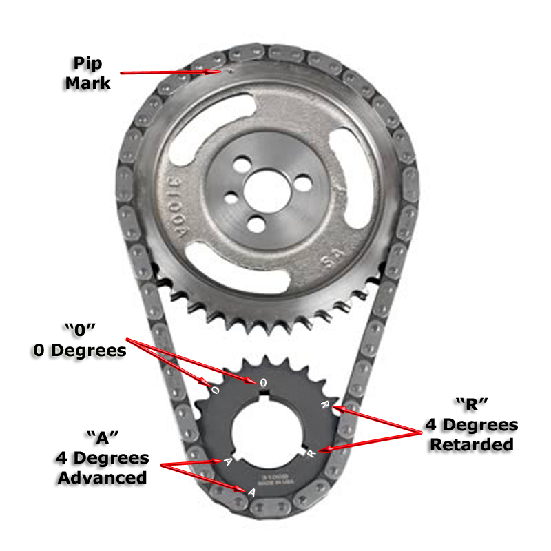
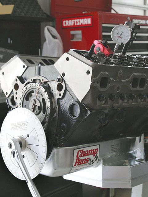
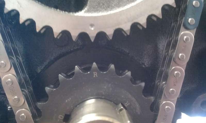
many guys don,t understand that on these multi key timing sets there areTHREE different letters,
on the crank gear and three matching keyway slots.
0 on the cam gear gets lined up with 0 on the crank gear, if the 0 crank key slot is used to index the cam at TDC
0 on the cam gear gets lined up with R on the crank gear, if the R crank key slot is used to index the cam at 4 degrees retarded from TDC
0 on the cam gear gets lined up with A on the crank gear, if the A crank key slot is used to index the cam at 4 degrees ADVANCED from TDC
BTW, read thru these
http://www.webcamshafts.com/pages/cam_glossary.html
viewtopic.php?f=52&t=480
viewtopic.php?f=52&t=322
http://www.thirdgen.org/sbc-camshafts-primer
viewtopic.php?f=52&t=90
viewtopic.php?f=52&t=727
viewtopic.php?f=52&t=181
http://www.popularhotrodding.com/tech/0 ... index.html
http://www.compcams.com/Community/Artic ... 2026144213
http://www.compcams.com/CAMQUEST/
http://www.crower.com/valve-timing-chart
http://cochise.uia.net/pkelley2/Overlap.html
http://www.compcams.com/Technical/TimingTutorial/

http://www.circletrack.com/techarticles ... index.html
viewtopic.php?f=52&t=2782&p=7214#p7214
viewtopic.php?f=52&t=112&p=139#p139
viewtopic.php?f=52&t=324
in case you don,t understand the chart, you take the engine displacement PER CYLINDER divided by the valve diam. then you use that on the chart to locate the lsa
example
lets assume youve got a 383sbc, 383/8=47.88
divide that by intake diam., lets say 2.02 and you get 23.7 youll see the ideal is near 105 lsa, but then you ask,WHY are most cams ground with a 110-112 LSA its because that tight lsa may maximize the peak volumetric efficiency,and peak hp/torque, it will also be far from ideal at low speed, with a lopey idle, or for emission testing or for ease of low and mid rpm ease of tuning or for sensors to read because of low rpm reversion in the intake runners.so a compromise with a wider LSA is used, sacrificing a bit of peak hp for better average drive ability and lower emissions and better mileage
http://www.herbertcams.com/560-580-lift-250-255-dur-050-110-lobe-center/
theres some rather significant advantages in ordering a cam that closely matches the engines
requirements, and after building dozens of similar engines youll notice some trends and you may want to tweak the cam timing, this of course requires both a good understanding of what your trying to change or accomplish and what the changes you intend to make are likely to do to engine performance.
heres a cam thats rather well known for producing good power in a 10.7:1 compression 406 SBC combo.
(use mostly for racing in a light weight car like a cobra replica)
Ive built several times in the past, it really requires the following matched components
210-230cc port heads, 5" scat rods on a forged crank, a 3600-3800rpm stall converter, a 4.11:1-4.56:1 rear gear and an automatic trans that shifts at 6300rpm under full load race acceleration.
a good single plane intake like the edelbrock VIC series, an 850 cfm carb, long tube 1 3/4" headers 1.6:1 roller rockers and a rocker stud girdle
heres the came basic cam, but with a few mods that provide about 20 extra horse power, but at the cost of a noticeably rougher lope in the idle
notice the tighter LSA and its a 4/7 swap cam version on a smaller base circle
look at the chart,
Critical Cam Event Criteria
By David Vizard
I just know someone is going to ask what qualifies me to write on this subject so let’s get that out of the way up front. During a large portion of 1985 I dyno tested more than 4,000 cam and rocker combinations in three differently spec’d SB Chevys for Crane.
The following year I did a similar but larger exercise on 2.0L Pinto motors and the "A" series Mini Cooper motors for Kent Cams in England. Between 1987 and now I have done a number of similar, if somewhat smaller, exercises for other well-known cam companies including Isky and Comp Cams.
All this amounts to a stack of dyno sheets that I would estimate at over six feet high! Now that’s out of the way let’s get down to business.
None of us who are in business for ourselves has to be reminded that time is money and in the high-performance engine building business that can be a sensitive subject. Anyone intent on building a customer base understands that quality, reliability and results at a reasonable cost to the customer are the key factors toward success. The problem is, if you spend the time to do the job to your very best the customer probably can’t afford it.
The trick here is to understand where the best compromises lay. If you can get 98 percent of the results in 25-50 percent of the time then chances are you will have satisfied customers.
There are probably very few places where it is more important to strike the right compromises than in the area of cam selection and installation. Let’s set the scene here. You have a customer with a moderate budget who wants a performance street motor built and part of the deal is that it’s up to you to select the cam for the job. Without spending forever researching it, and nearly as long installing and timing it, what cam will be the best for the job? Here are some pointers that will help you make better choices in a number of areas for a better end result.
Duration
All too often, cams are selected on the basis of duration. This is not the best criterion, however. Overlap is a significantly more influential factor. The key here is not to go overboard on this.
The principle parameter dictating how much can be used is strongly influenced by the ratio of displacement relative to cylinder head airflow. This means large motors with less than adequate heads not only tolerate more overlap without losing streetable qualities but also need more to produce best output.
When the head flow is high in relation to the engine size overlap needs to be moderated. The key issue then is to strike a good compromise between overlap and duration. My advice here is to be conservative on duration and moderate on overlap, but try to go for as much lift as can be achieved without mechanically compromising valve train reliability.
Getting back to duration and overlap, we find that in considering these two factors together we are dictating what the cams Lobe Centerline Angle (LCA) will be.
LCAs
There is much said about LCAs that needs to be thrown out with the garbage. First let me make one major point quite clear. For a given spec of engine there is only one LCA that will give optimum torque and horsepower. It is not, as many cam company techs would have you believe, a variable parameter.
Consumers are often given the impression that cams need to be wider for street use than performance/race use so as to preserve idle quality. If a cam has to be ground on a wider LCA to preserve idle quality it is because the duration selected was too much to begin with. Fixing one cam selection mistake with another is not the way to go!
Here is something that, even as a professional engine builder, you may not be aware of. Some cam companies deliberately grind their off-the-shelf cams on wider-than-optimal LCAs. Why? Because they understand their customers.
Most performance orientated buyers a) are duration fixated and b) subconsciously or otherwise, adhere to the Stroker McGurk principle. This principle holds that "if some is good, more must be better and too much is just right." Although that may be true if we are talking bank balances it is most certainly not the case with cams.
By spreading the LCAs and reducing the overlap the cam grinders can give their customers a bigger cam to enhance bragging rights while still preserving some streetability for that same over-exuberant customer. Just how much this policy, consciously or otherwise, is adopted varies from company to company.
Being aware of this will go a long way to explaining why, when you look through different company catalogs, the cams for a given application differ by so much. If you ever thought that they can’t all be right then you are already a rung or two further up the ladder than the rest of the crowd.
For a truly impressive performance engine, its all about having lots of torque throughout the rpm range used. When considering valve events it pays to remember that, especially at low speed, torque is greatly influenced by the closing point of the intake valve. Tighter LCAs close the intake sooner as do cams timed in with more (and hopefully correct) advance.
So what is the price paid for a LCA that is artificially spread from optimum? Answer: a loss of ft.lbs. throughout the rpm range. Obviously the best situation is to have the optimum LCA but in the absence of this what are the best compromises?
The best way to cover this is to start from an optimum and see what we lose by first going too tight (a smaller number) then too wide (a larger number). If we have an optimally spec’d LCA for a race engine then we find that as the LCA is widened torque over the entire rpm band used drops off quite rapidly. For example, in a 350 SB Chevy, two degrees too wide can mean a loss of 20 or more ft.lbs. throughout the rpm range. On the other hand 2° too tight will have almost no effect on the output over the rpm range used while racing. If the LCA is too tight the motor needs to turn higher rpms before it comes on-the-cam and the idle is rougher. For a race engine then it is best to err on the tight side rather than the wide side. Because the idle quality goes as overlap is increased it is better to err slightly on the wide side if we are talking street usage. Here I am talking 2° off optimum, not the 4° to 6° and even 8° that is often seen. If you are installing such cams in commonly modified engines then you might want to consider upgrading your source of cam advice.
Cam Timing
If we are dealing with most domestic V8s then we have three options when it comes to what can be a time-consuming job, namely installing and timing the cam. The first and fastest option is to just install the cam and not bother to check to see where it is. This amounts to taking on blind faith the cam grinder’s ability to grind the cam right and the accuracy of the drive train from crank to cam. Granted, much of the time this will work but the other side of the coin is that a lesser, though still significant, number will not.
The second option is to use the commonly available multi-keyway gears. These are normally cut so that you can move in a 4° increment either way.
Lastly there is the "do it right by whatever means it takes" method. This, in its most convenient form, can involve adjustable timing gears; less conveniently, offset dowel pins; and the worst-case and most time-consuming scenario, shims and files.
Going with option number one is fine if you know that the type of engine you are working on has consistent timing gears and that the cam you are using is also ground right (usually the case if it is a quantity-produced off-the-shelf item). If this does work for you I don’t have anything further to say on the subject but if options two or three are it, then the following guidelines might prove useful.
If you are using a 4° increment multi-keyway gear then the chances of getting the timing within +/- one-half a degree are 4 to 1.
Let us consider the situation when one keyway puts the cam 2° retarded and the other 2° advance. Which do you go for? Assuming the cam has optimal valve opening events to start with then, in terms of power production, the output drops off faster if the cam is retarded than if it is advanced.
In the case in question, 2° too much advance will still typically deliver 99.7 percent of the engine’s capability whereas 2° retarded can drop output by as much as 3 percent. Also it is worth taking into account that as the valve train drive wears the cam becomes retarded. In the first 5,000 miles cam and timing chain wear can bring about a half-degree of retard.
The worst-case scenario is when the choice is between 1° retard and 3° of advance. The difference between optimal timing and one degree retarded is barely measurable on the dyno and, if the drive system is unlikely to change that situation, then go with the one degree retard. If the initial timing chain/gear wear is a factor in the equation then go with the 3° too far advance, especially if your customer is likely to shoot some nitrous into the motor. After 5,000 miles the advance is likely to be only 2-1/2° too much and that is still marginally better than 1-1/2° retarded.
It is commonly accepted that if a cam is too advanced it enhances low-end output because the intake closes earlier. It is also generally held that if the cam is retarded it will enhance top-end output at the expense of low end mainly because the intake closes later.
In reality the complete picture is a little more complex. If you find that retarding the cam makes a worthwhile difference in top-end output then part of the reason is that the cam’s basic valve events are not that close to optimal. The same goes if low end increases by any significant amount.
If cam events are virtually optimal on the cam then timing the cam correctly becomes more important. If events are not "right on" then we find that retiming the cam may put one event nearer optimal while others move away from optimal. Under these circumstances retiming the cam only produces marginal changes. These may show a certain advantage in one part of the rpm range at the expense of another.
However if the cam is capable of delivering optimal valve events in every respect we find the cam becomes much more sensitive to timing. An error in timing means that all events are now displaced from optimum. The result is that the engine can lose output everywhere over its entire working rpm band.
The bottom line here is if you know the cam is well speced for the application it becomes more important to time it in as the chance of impaired results is greater. "
many guys don,t understand that on these multi key timing sets there areTHREE different letters,
on the crank gear and three matching keyway slots.
0 on the cam gear gets lined up with 0 on the crank gear, if the 0 crank key slot is used to index the cam at TDC
0 on the cam gear gets lined up with R on the crank gear, if the R crank key slot is used to index the cam at 4 degrees retarded from TDC
0 on the cam gear gets lined up with A on the crank gear, if the A crank key slot is used to index the cam at 4 degrees ADVANCED from TDC
BTW, read thru these
http://www.webcamshafts.com/pages/cam_glossary.html
viewtopic.php?f=52&t=480
viewtopic.php?f=52&t=322
http://www.thirdgen.org/sbc-camshafts-primer
viewtopic.php?f=52&t=90
viewtopic.php?f=52&t=727
viewtopic.php?f=52&t=181
http://www.popularhotrodding.com/tech/0 ... index.html
http://www.compcams.com/Community/Artic ... 2026144213
http://www.compcams.com/CAMQUEST/
http://www.crower.com/valve-timing-chart
http://cochise.uia.net/pkelley2/Overlap.html
http://www.compcams.com/Technical/TimingTutorial/
Last edited by a moderator: