The True Junkyard Ford 302

Stuart Wall

Member
Let it be known, first and foremost, that this thread is about a E7TE roller short block purchased at a self-service junkyard during a 40% off sale. The fact that it was on sale should help you understand the priorities of the build. It is also the first engine I have ever put a dial indicator on, and the first Ford I have ever built. So, with the experimental nature of this project and full disclosure of my lack of experience, take whatever learning you wish from it at your own risk. If this motor proves to be a dud, or dies in the first 100 miles, I promise to be honest about it.

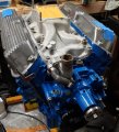
What: E7TE non HO block, GT40 iron heads, factory HO cam, performer RPM (American casting because I bought an old crusty used one), Holley 600 vacuum secondary, electric ignition and fan. Headers, single 3" exhaust.

Goal: to use 87 or 89 octane, horsepower will be whatever it will be, stock converter, 3.25 gear, C4 trans, 2850 pound car.

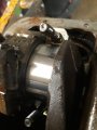
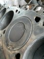
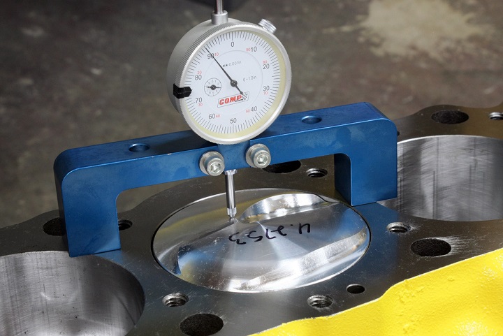
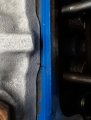
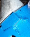
The block is on my engine stand. I am estimating it to have about 150K miles on it. It had a replacement timing chain that was tight, re-built 1978 heads that I left in the junkyard, and cross hatching still visible. The piston tops had no valve reliefs and are .020 out of the hole on one bank, and .015 out on the other. I took it upon myself to create valve reliefs, as there were small dents in 2 pistons. I have also scrounged up a Ford HO cam from a 1995 mustang GT. The cam is installed dot to dot with a new chain + a mechanical fuel pump eccentric. I have also replaced the rod bearings. This is how it sits currently. pictures are not in chronological order.

The heads, GT40 iron, were purchased out of the junkyard 2+ years ago, and were meant for a different engine, but will use them on this. I read a bit about "porting," and many warnings about how easily these can be messed up, but finally decided to do light bowl blending as outlined at http://diyporting.com/ . The valves got lapped in, new seals, and a spring kit. I had .040 milled off the bottom to go from a 65 cc chamber to a 58 cc chamber. I will admit for this application, .040 was probably too much.....but I was under the impression that any block I could find in a junkyard would have pistons below the deck.

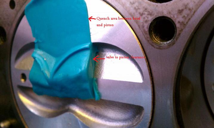
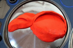
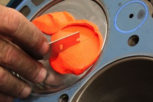
My next chore is placing the heads on the block with .055 sheet metal shims and put clay in all 8 cylinders to check clearances and make sure ALL of the valves are in the home made cut outs.
 

Attachments

  • 20200110_142650.jpg
    20200110_142650.jpg
    85.6 KB · Views: 12
  • 20200114_174107.jpg
    20200114_174107.jpg
    85.5 KB · Views: 10
  • 20191228_144127.jpg
    20191228_144127.jpg
    107.5 KB · Views: 9
I have to be impressed that you took the effort to cut valve notch clearance ,
and try to keep metallic trash from getting into the engine
you may want to read this thread
http://garage.grumpysperformance.com/index.php?threads/checking-piston-to-valve-clearances.399/
having the piston extend past the block deck surface is not all that rare,
find_tdc.jpg

but its generally seen mostly with pistons that have a combustion chamber shaped pop-up
dome, obviously degree the cam in and realize it can be advanced or retarded to gain the best physical piston to valve clearance if thats required, you really need a degree wheel and a dial indicator and stand to do that correctly

WITH THE CORRECT SOFT WARE BOTH THE PISTON TO VALVE CLEARANCE AND CAM TO ROD CLEARANCE CAN BE CALCULATED
BUT ANY COMPETENT ENGINE BUILDER WILL PHYSICALLY VERIFY CLEARANCE
PtV3.jpg

clay6.jpg

valclear2a.jpg

vcl1.jpg

vcl2.jpg
 
Last edited:
I measured the cam a few times until I had repeatable numbers. I came up with: IO @ .006 15 BTDC, @ .050 12 ATDC IC @ .050 41 ABDC, @ .006 74 ABDC
EO @ .006 60 BBDC, @ .050 39 BBDC EC @.050 10 BTDC @ .006 23 ATDC 116 ICL 116 LCA

The Pat Kelly calculator ( I did a lot of reading after I found out I had to deal with 9.94:1 with shaved heads) says I will have a dynamic compression ratio of 7.54:1 . That seems low...but I guess the factory did not want their mustangs to detonate? this should run on 87 octane? Unless the calculator does not use at .006 to find duration? I used .006 at the lifter.
 
The 95 GT cam is installed. I put clay in every cylinder to check clearance and verify all valve pocket locations. I got .100 on intakes and .120 on exhaust, so if I do a different cam someday there is room for a bit more duration.

Heads are bolted down with new dowels, thick hardened washers from the hardware store, and a .055 gasket on the .020 out bank, and a .050 gasket on the .015 out bank (drivers side). The old head bolts were not torque to yield, and were re-used. I used a torque wrench with a dial on it, and I could tell when the fire ring on the gaskets was crushing....at 50 ft. lbs. All bolt holes were chased, the top ones got oiled and the bottoms got thread sealer.
I started shimming all my pedestals at .040 to match what was removed from the head bottom, and by adding another .010 to 3 of them and subtracting .010 from one, all hit 20 ft. lbs. with 1/2 to 2/3 turn.

Up next is sorting out the intake and deciding if port alignment will be a concern, and how I will end up doing it. I have 3 different sets of intake gaskets.....I bought a bunch of parts for 40 bucks which included a complete 302 engine set with some additions. I may install the intake with one set, mark the location of it, and remove it to see how it lines up @ its torqued position, although I have read that for a mild application like this it may not be of much benefit.
 
Looks like you are doing a great job of checking things as you go!

When you talk about port alignment, do you mean just lining up the ports and if the head is bigger or
smaller than the intake manifold that is not a concern as long as they are centered on each other OR
are you considering actually matching their size and alignment ???

You shaved off .040" from the head to block surface, did you cut anything from the intake surface of
the head ?
 
Looks like you are doing a great job of checking things as you go!

Thank-you. This is mostly a first time event for me, and I have read many, many hours worth of stuff on the internet. This motor is so common that information is over-abundant.

When you talk about port alignment, do you mean just lining up the ports and if the head is bigger or
smaller than the intake manifold that is not a concern as long as they are centered on each other OR
are you considering actually matching their size and alignment ???

For this build, I just want the alignment to be as good as I can get it without removing material. I moved the intake gaskets slightly, one towards the front and one towards the rear, by dremeling the alignment tabs. this centered them on the ports. I used a straight edge across the tops of the ports in the head and put a mark on the front of the head, also did the same for the intake and marked that, so when it got torqued down I could see if the two lines aligned. I did a vertical line up the edge of a port on the head and marked that on top, and marked the top of the intake for the same port edge. I had to pull the intake forward up against all the bolt edges before torquing it to get it close. I would have had to file out all the bolt holes to get perfect alignment front to back. Up and down alignment was off about .040......ahem, I shaved only the bottom of my heads. All in all, considering the intake port was slightly smaller than the head, what little miss alignment I can see should be tolerable. For a precise fit, a tiny bit off the intake, or intake side of head, would have allowed the manifold to sit lower and be more perfect.
 
I used a straight edge across the tops of the ports in the head and put a mark on the front of the head, also did the same for the intake and marked that, so when it got torqued down I could see if the two lines aligned. I did a vertical line up the edge of a port on the head and marked that on top, and marked the top of the intake for the same port edge.
A few pics would go a long ways toward helping us understand your process if that's important to you.
 
A few pics would go a long ways toward helping us understand your process if that's important to you.

lol....yes....I had to crop these to make them upload. This is the tail end of the process....and although the ball point pen marks are fat and awkward, I am actually trying to use the edge of the pen marks, but a real scribe mark would probably be better. At least I did learn that my manifold ports and head ports are out of alignment on two sides, maybe about .050 each way. If that was a concern for this build, I would have to take the intake off and fix it.

If I were going all out, I would also have to mark every port and treat them all individually. I never understood the tediousness of getting everything exact. It would seem to cost a small fortune to pay someone to undertake every detail of a perfect build....or worse yet would it be for the extremely fussy builder that would give attention to all this stuff without the extra payment.
 

Attachments

  • 20200303_103641 (2).jpg
    20200303_103641 (2).jpg
    126.4 KB · Views: 8
  • 20200303_104031 (3).jpg
    20200303_104031 (3).jpg
    179.9 KB · Views: 8
lol....yes....I had to crop these to make them upload.
Check out this thread, it has a link to free software that will reduce the file size, image size and
add notations like text and arrows.

http://garage.grumpysperformance.com/index.php?threads/photo-software-and-resizing.14044/

If I were going all out, I would also have to mark every port and treat them all individually. I never understood the tediousness of getting everything exact. It would seem to cost a small fortune to pay someone to undertake every detail of a perfect build....or worse yet would it be for the extremely fussy builder that would give attention to all this stuff without the extra payment.

With a few tools, many of the tedious things can be done yourself and not pay someone. Some things
you would never know if they got done, just have to take their word. There are lots of procedures for
matching the intake ports for size and alignment, below is mine. I enjoyed the process for making
things perfect or as close as I can get.

http://garage.grumpysperformance.co...cedure-step-by-step-guide-with-pictures.5378/

If you have time for a long read and want to see how many details one person can manage in a 2 car
garage read below.

http://garage.grumpysperformance.com/index.php?threads/tbucket-engine-project-dart-shp.3814/
 
That doweling process is clever, and I would have to say it is as accurate as I can imagine any process could be. Very well done sir! The problem with the SBF intake is that it bolts straight down into the head, and I dont know how to predict where the alignment will be after it is all torqued down. If I were to drill dowel holes through the intake and into the head after assembly, and then take it apart, I should have good reference points? HMMMM.....Ya got me thinking.....
 
That doweling process is clever, and I would have to say it is as accurate as I can imagine any process could be. Very well done sir!
Thanks, appreciate the nice compliment !

If I were to drill dowel holes through the intake and into the head after assembly, and then take it apart, I should have good reference points?
After you have the hole drilled thru the intake into the head, then drill the hole in the intake slightly
larger. You need to be able to see the reference in the head before you torque the manifold down. Another
words, when you set the intake on, how will you know if it's going to be aligned when torqued.

You will want to document the gasket you use, so you can get the same gasket any time the intake comes
off. A different thickness will throw off your alignment if it's considerably different in thickness.
 
You will want to document the gasket you use, so you can get the same gasket any time the intake comes
off. A different thickness will throw off your alignment if it's considerably different in thickness.

That is for sure. I have had to document parts used in this build in case I need to ever tear it down. I have two different brand and thicknesses in head gaskets alone, and I have to remember which goes to what side. Lol...I will not remember what I did if I dont write it down!
 
Getting real close. I will get a parts store distributor that comes with a steel gear and a vacuum advance, and re-curve it when everything is set up and I have an idea how much advance this engine will like. I am leaning toward a GM 4 pin distributor module, as it optimizes the dwell also? The ford version of the 4 pin will not work with the distributor I need, and the ford version that does work with this distributor has a set dwell. Probably overthinking this for a motor that will poop out at 5800rpm, but hoping to do it only once. This distributor and module will be the only "new" parts in the whole build....other than the oil filter and plugs.
 

Attachments

  • 20200327_182932 (2).jpg
    20200327_182932 (2).jpg
    164.8 KB · Views: 5
For TEOTW scenario I'd get a points type distributor --just in case. I keep spares for my Chevy V8s in case the world ends or electronics get fried.

I love you working with a Ford engine--they are most dependable. Just not cheap for parts.
 
For most people yes, but not for you and I. Learning something is where the fun happens, doesn't
matter how much you spend!

lol....yes. But I have been spending more time in school than on the play ground it seems....but I am looking forward to re curving that distributor as though getting it to run as close to perfect as I can get is better than actually driving it? My daily driver gets no such love or care. it is just a mule. I guess the one car that I can understand well enough to puzzle over it gets the love.

For TEOTW scenario I'd get a points type distributor --just in case. I keep spares for my Chevy V8s in case the world ends or electronics get fried.

I have a 1970 step van with a points fired 6 and a manual trans. I have collected parts to convert it to points triggered electronic ignition.....but it waits. The extra points distributors you got are cheap insurance....and I have wondered more than once if that old van is going to be my hero someday. Thing is, we would probably be limited to gas on hand, so the last drive would need to be well planned.
 
lol....yes. But I have been spending more time in school than on the play ground it seems....but I am looking forward to re curving that distributor as though getting it to run as close to perfect as I can get is better than actually driving it? My daily driver gets no such love or care. it is just a mule. I guess the one car that I can understand well enough to puzzle over it gets the love.


I have a 1970 step van with a points fired 6 and a manual trans. I have collected parts to convert it to points triggered electronic ignition.....but it waits. The extra points distributors you got are cheap insurance....and I have wondered more than once if that old van is going to be my hero someday. Thing is, we would probably be limited to gas on hand, so the last drive would need to be well planned.
Points will continue to work in an EMP strike. Electronic ignition gets fried.
 
Points will continue to work in an EMP strike. Electronic ignition gets fried.

True. If I used points to trigger a Ford TFI module and it fried, I would just have to re-wire the system to run the current back through the points....and re-employ the resistor wire.....yuk. And maybe swap the coil back.....and hope I am not in a hurry!!! oh yeah, and put the condenser back...lol.
 
Back
Top