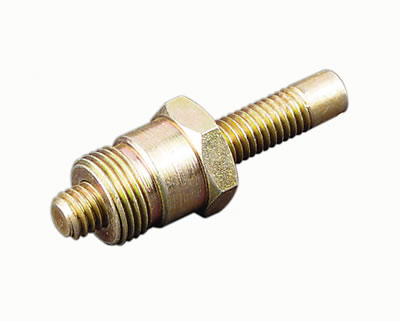
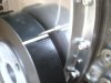
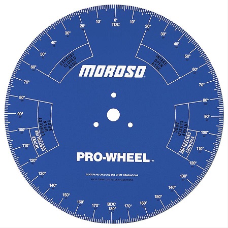
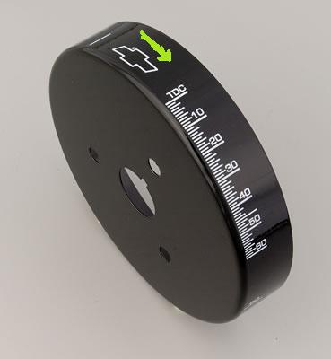
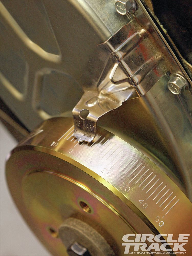
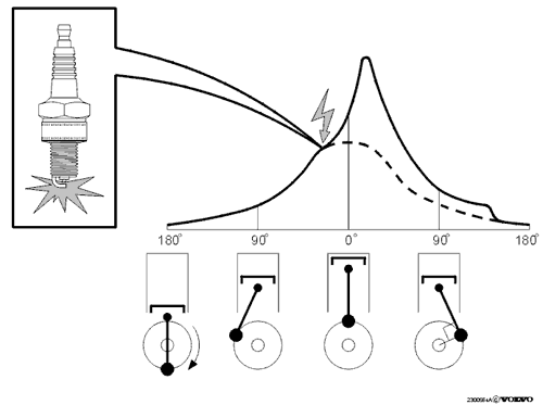
these things are a deceptively simply but necessary component on your engine, they range from the cheap stamped steel, and non adjustable versions to the much nicer adjustable versions, ONE basic thing youll need to know is where TDC, 90,180,270 degrees are located if and when you get involved with tuning your engine ignition timing advance curve or adjusting valves if you do in with the engine not running, ignition spark should be bright blue and impressive, if its, weak,narrow, yellow or red theres a problem so research the cause, verify the coil and voltage
stock timing marks are very limited in the extent of timing changes that can be indicated
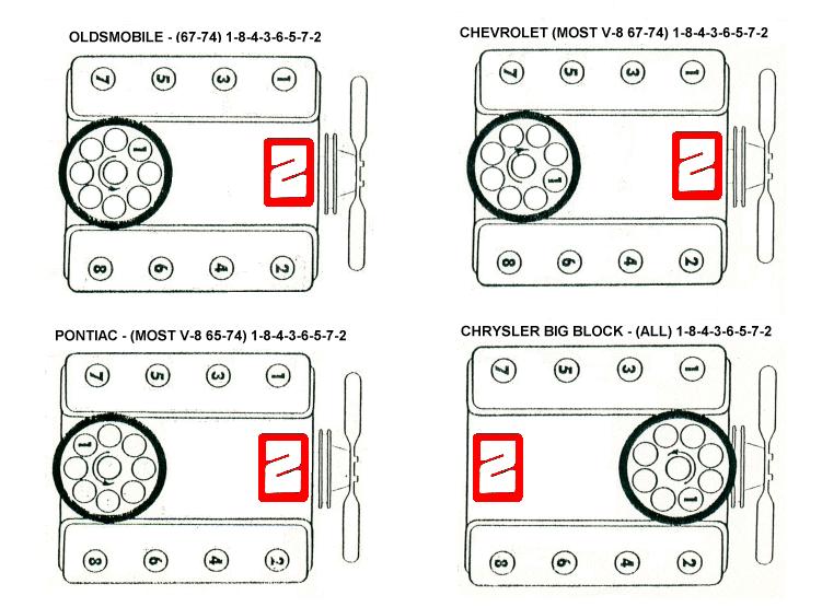
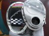
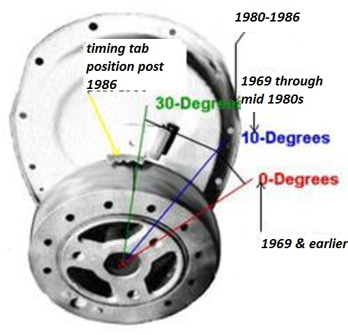
There are 3 timing mark locations on the balancers on SBC engines that I know of, therefore there are 3 timing tab locations also. Plus the tab location varies with small and large balancers as far as the distance from the crankshaft.
READ THIS RELATED THREAD, ON FINDING TDC
http://garage.grumpysperformance.com/index.php?threads/finding-top-dead-center.967/
http://garage.grumpysperformance.co...evy-damper-is-designed-for-your-engine.11561/
http://www.superchevy.com/how-to/ad...now-about-vacuum-advance-and-ignition-timing/
https://www.speedwaymotors.com/Speedway-Motors-Pontiac-V8-Pro-Series-Distributor,443619.html
RICK L posted this bit of info
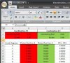
"#1 is the balancer TDC mark lines up with the keyway. This is the configuration for 1968 and older balancers. There are two timing tabs for this, one for 6"+ balancers, and one for 8" balancers. This would not include 400 engines since they were all made after 1968.
#2 is the balancer TDC mark is 10 degrees CCW from the keyway, looking at it from the front. This is the most common location for 69-up engines, and that includes 400s. There is a bolt on timing tab that works with this setup.
#3 is the balancer TDC mark is 30 degrees CCW from the keyway, again looking at it from the front. Only a few 69-up engines were made this way. You have to point the timing light through the gap between the water pump and timing cover. I don't know if any 400 engines were built this way, I really doubt it. I had a 76 350 truck core that had this balancer and timing mark on it. The tab was welded to the timing cover instead of the usual bolt on tab in those years. The balancer was also very light for an 8" balancer."
I found this info posted several places
The three most common locations for the timing mark on the damper
The exact years of the type of damper timing marks overlap one another, depending on the exact application.
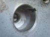
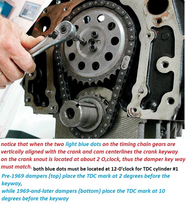
The pre-1969 damper has the TDC line on the outer ring at the 2:30 o’clock position- or 2º before the keyway centerline- i.e. the line is to the LEFT of the keyway, looking at the front of the damper or engine. The keyway is seen in the ID of the damper nose.
The damper used from 1969 to about 1984 has the TDC line at the 2 o’clock position- or 10º before the keyway. You'll find that aftermarket dampers are the 10º type, as are the bolt-on tabs sold by the aftermarket, unless they're adjustable.
Warning Note: This includes the SBC 400, although the 400 damper is counterweighted because the engine is externally balanced. Do not mix and match internal and external balanced dampers!
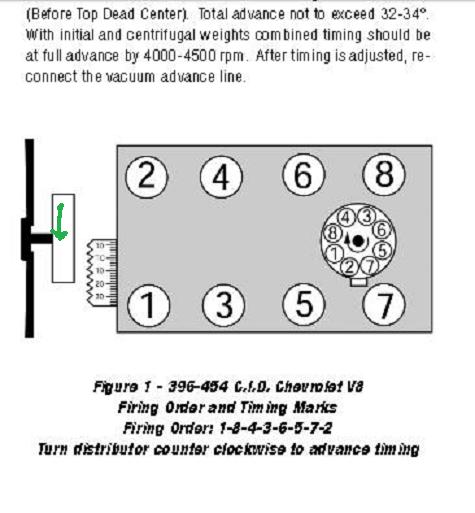
A third timing mark was used from (some) 1978 to about 1995, and nearly all 1984-1995. It is at the 12 o’clock position- or 40º before the keyway. This damper uses a timing cover that has the tab welded on at about the 12 o'clock position. Professional Products lists the years for this type damper line as being 1984-1995 and is a 6-3/4” diameter damper.
READ THESE CLOSELY RELATED THREADS
viewtopic.php?f=70&t=4683&p=12672#p12672
viewtopic.php?f=70&t=967
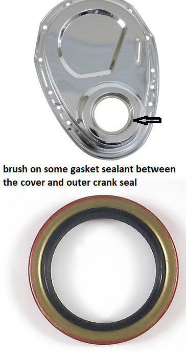
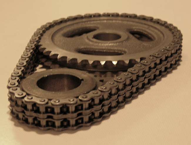
the double roller cloyes timing chains tend to last longer before they wear and have excess slack
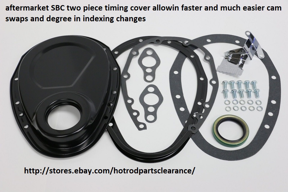
and they can be used with the stock O.E.M timing chain cover

TRUE DOUBLE ROLLER TIMING CHAIN SETS FROM QUALITY MANUFACTURERS TEND TO BE MORE DURABLE

KEEP IN MIND that theres TWO totally different damper and timing tab locations that are correct on the SBC engines and you must use matched components for almost all years the ting tabs and dampers show TDC to be at about 2 o,clock, but theres a few applications that used a 12 o,clock timing tab and damper combo and you can,t mix&match the two types
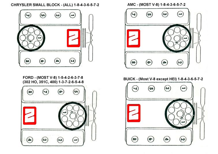
(Windshield)
_____6___5
___3_______7
___4_______2
_____8___1
(Radiator)
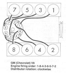


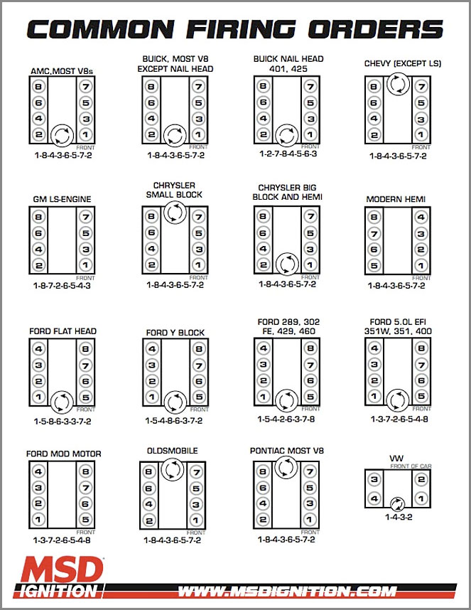
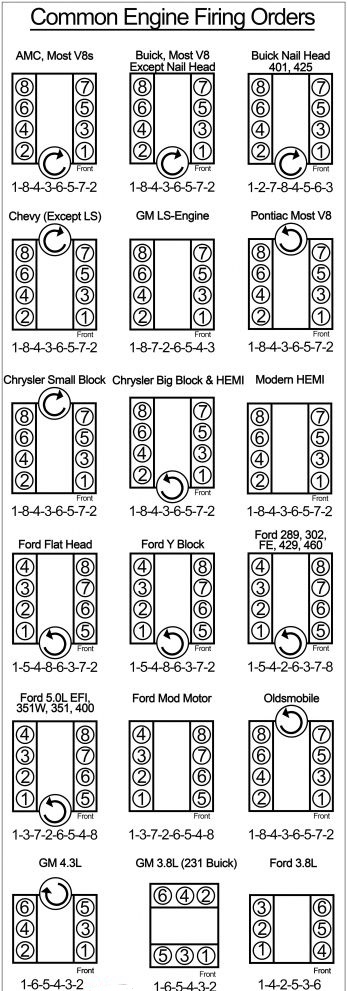
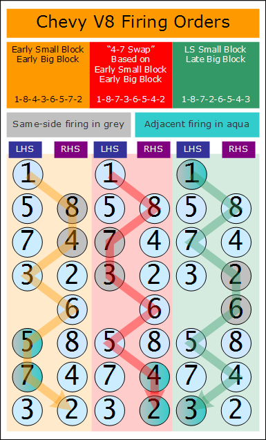
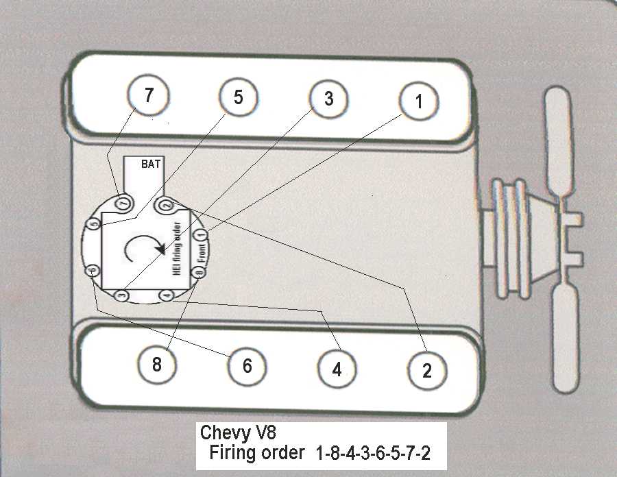
the fact is that due to manufacturing tolerances a dot-to-dot install will frequently be a few degrees off! now most guys might never notice, but it can and frequently does effect the engines power band so getting it correct helps and eliminates one potential source of problems (be damn sure you verify the cams degreed in correctly and the ignition firing orders correct and all the distributor wires go to the correct cylinder,s spark plugs and distributor cap locations)
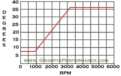
obviously you need to have a consistent base line advance curve to work with,
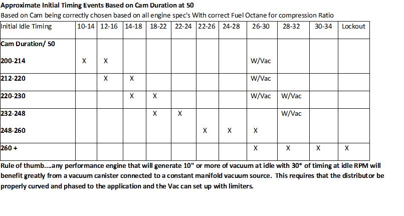
on most Chevy v8 engines that run cams designed for street/strip use Ive generally found a advance that goes from about 8 degrees at idle speed (800-900rpm in most cases) and smoothly advances the ignition to about 36 degrees or about 28 degrees advance from where it started at to reach 36 degrees at about 3200rpm , is generally a good place to start, or about 82 rpm increase per degree of ignition advance , up to about 3200rpm, where increase turbulence and squish tends to speed the burn process, you can then play with the engine and determine what changes MIGHT be require
WATCH THIS
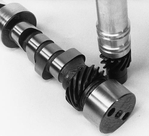
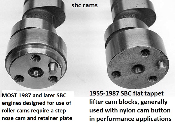
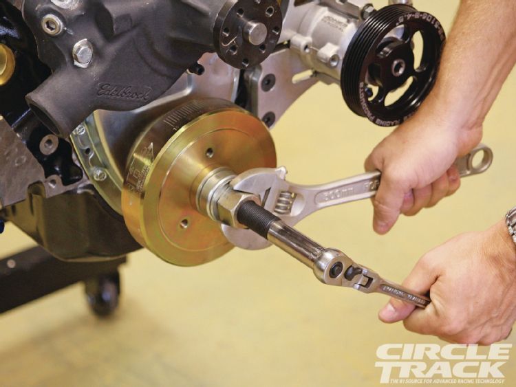
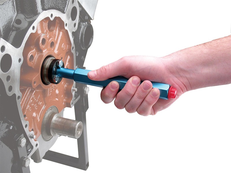
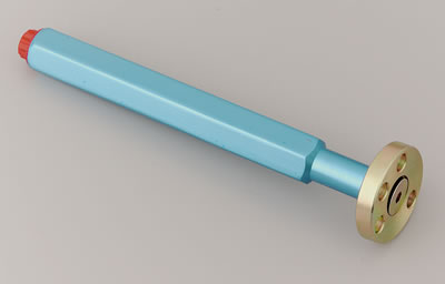
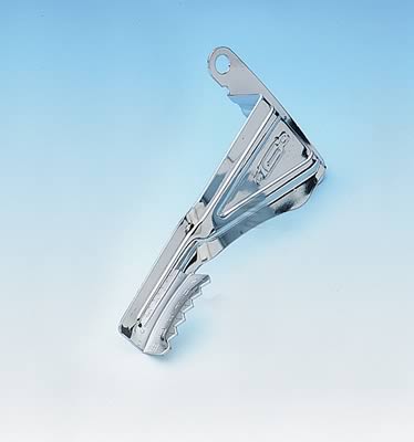
use of a camshaft install handle generally reduces the chances of damaged cam bearings
YOU MIGHT WANT TO READ THESE THREADS ALSO
http://www.familycar.com/Classroom/ignition.htm
viewtopic.php?f=70&t=967
http://www.corvette-restoration.com/res ... ing101.pdf
http://stores.unleashedcustommachining. ... gories.bok
viewtopic.php?f=70&t=875
viewtopic.php?f=70&t=202
viewtopic.php?f=53&t=562
http://www.atiracing.com/products/dampe ... ctions.htm
viewtopic.php?f=53&t=279
viewtopic.php?f=52&t=130
viewtopic.php?f=52&t=90
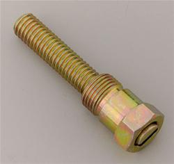
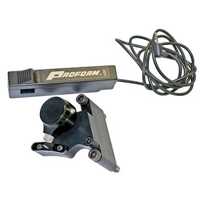
SUMMIT RACING AND JEGS CARRY DOZENS OF DESIGNS

you can even find them with a built in timing light strobe
http://store.summitracing.com/partdetai ... toview=sku
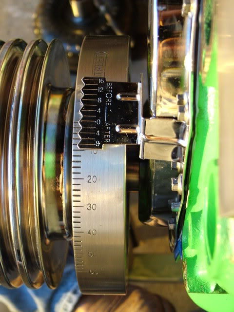
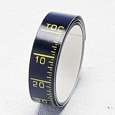
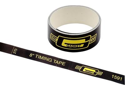
you generally use them with a timing tape like this
http://www.summitracing.com/parts/MRG-4599/?image=large
http://www.summitracing.com/parts/MRG-4600/?rtype=10
http://forum.grumpysperformance.com/viewtopic.php?f=50&t=723
http://www.summitracing.com/parts/MRG-4598/
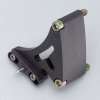
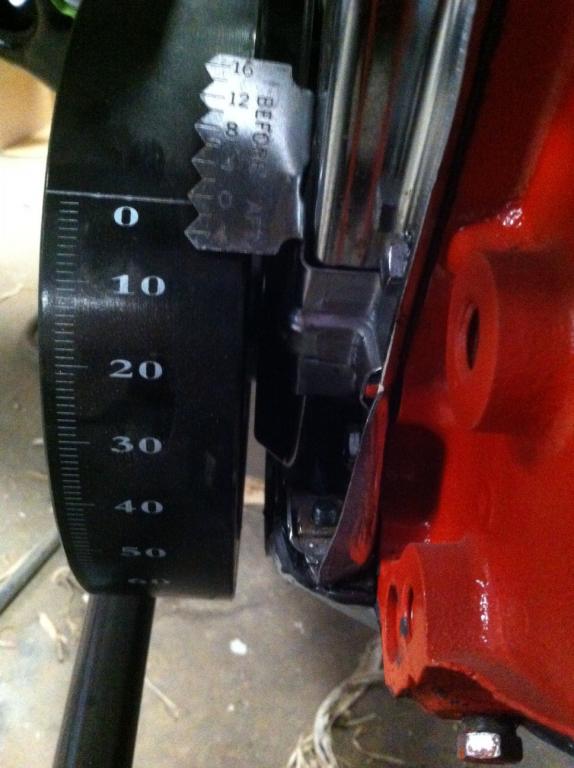
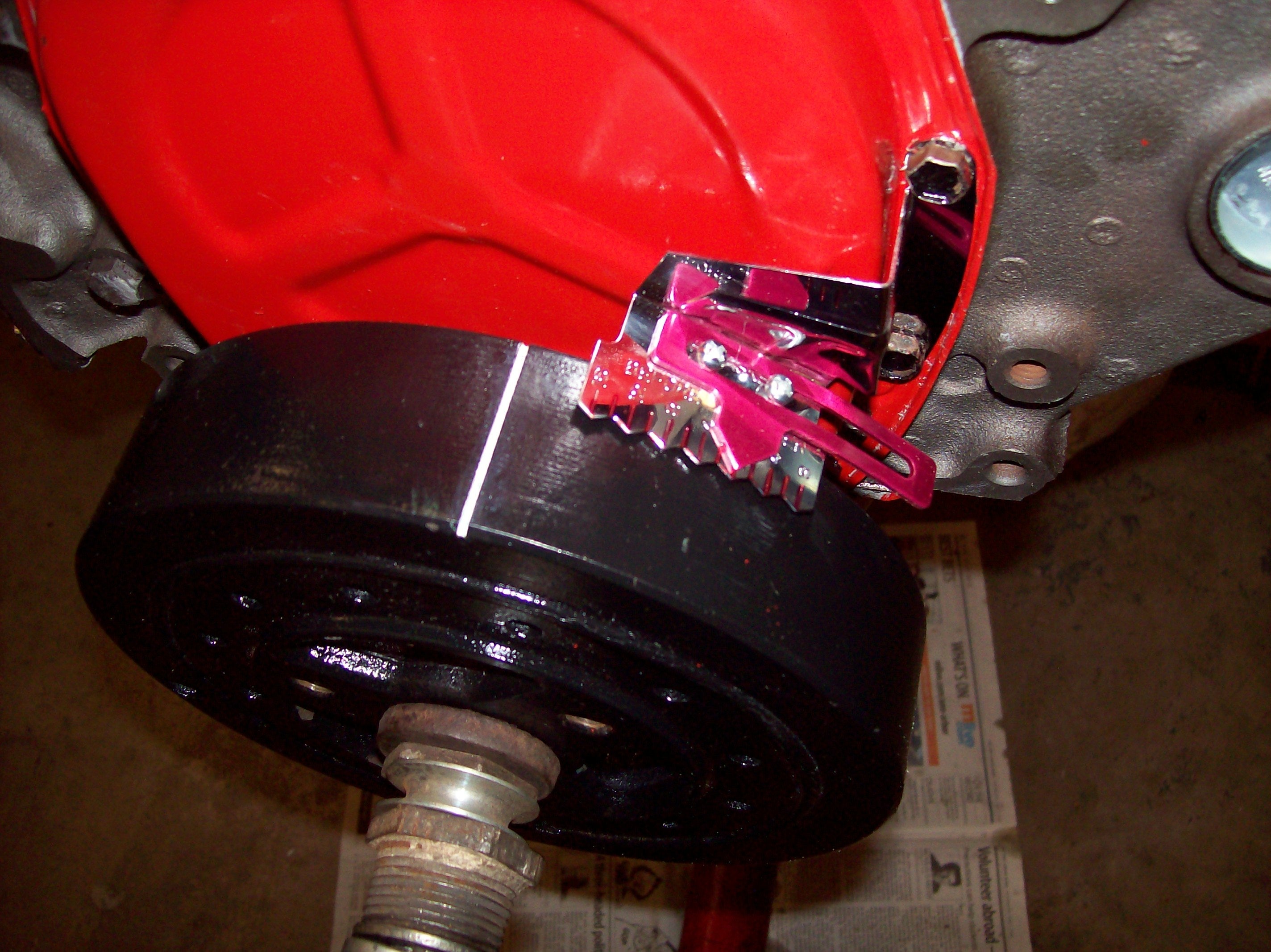
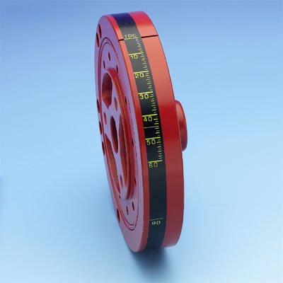
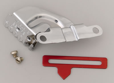
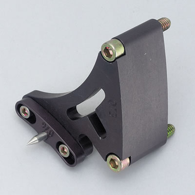
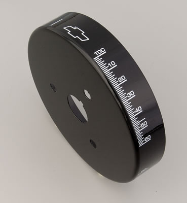
the use of timing tape on the damper is a huge help and yeah, the glue on the tape tends to get loose so use some contact cement sparingly, the contact cement works, but a simple spray coat of a clear lacquer spray paint sprayed over the tape and allowed to dry locks it on the damper fairly well also, or you can spend just a bit more, and buy a damper cover, and adjustable timing tab, just remember to verify TDC

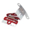
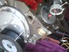
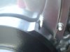
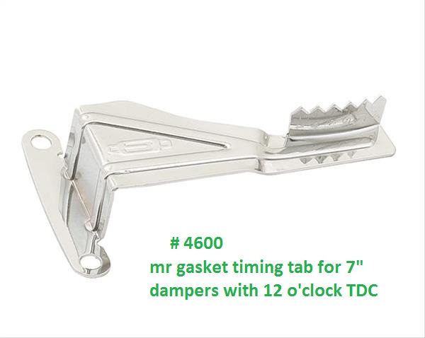
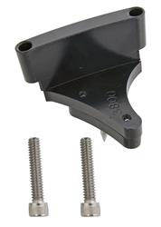
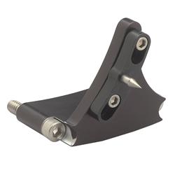
they make these timing tabs for BOTH SBC AND BBC , and IN SEVERAL DIFFERENT DAMPER SIZES ,SO BE SURE YOU ORDER THE CORRECT ONE FOR YOUR APPLICATION, remember theres been both different damper diameters and two common and actually three different locations on the timing tab index location for small blocks, so make darn sure the damper you use matches the timing tab your using, by verifying top dead center and not assuming the parts you have are correct, some SBC dampers and tabs fit/index on the timing tab location at about 2 o'clock on the timing cover, a few at about 12 o'clock
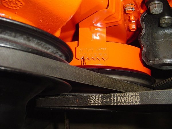
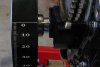
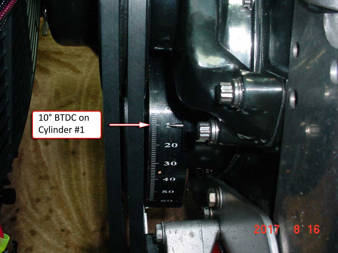
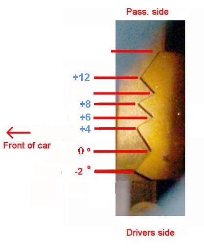
this picture shows almost exactly where the timing mark should be when the timing light flashes at idle
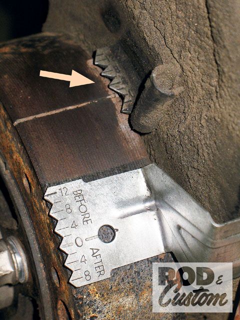
start with the basics, verify tdc (top dead center)on the damper and timing tab are truly indicating TDC
if it is it sounds like the cam was installed a few degrees out of its intended index with the crank rotation(easily done if installing it (dot-to-dot)
keep in mind that if the cam was installed without degreeing it in, with a degree wheel theres at least some chance the cams indexed incorrectly and its installed several degrees out of sinc.
viewtopic.php?f=52&t=966&p=1682#p1682
viewtopic.php?f=52&t=90
viewtopic.php?f=52&t=196
viewtopic.php?f=52&t=4548&p=12699&hilit=timing+marks#p12699
one common problem I see many guys go thru is the result of not understanding what visual clues, or obvious symptoms indicate, when they see them.
when your breaking in a new engine or cam, one common problem indicator is the headers running excessively hot
EXAMPLE
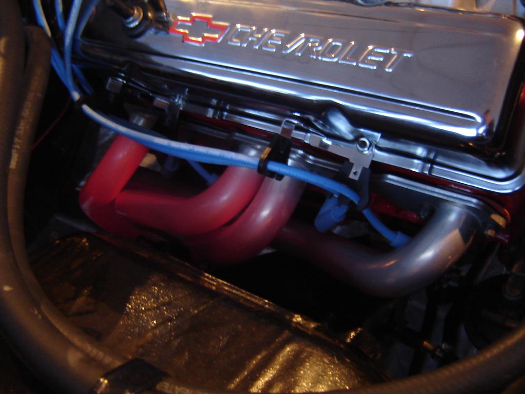
btw notice the front header tube seems to be a bit cooler and each header tube as you move to the rear looks a bit hotter, thats because the engine compartment air flow cools the headers less effectively as its heated as it moves from the radiator rear ward
the picture above is commonly the result of having Your ignition timing too retarded for the 2500rpm-3500rpm your supposed to be lapping a new cam in at for the first few minutes,or the ignition advance curve rpm is to slow with a light load. Under a light load combustion is a slower process. Some of the combustion is still taking place after the exhaust valve opens which will make the headers glow.
if your running a LEAN due to either jetting, tuning issues or a large vacuum leak....the overly lean fuel/air mix tends to raise the exhaust temps, obviously an IR temp gun can be very useful in spotting this condition early, but its even more useful because it can easily tell you if only one or two headers are running significantly hotter, usually indicating a vacuum leak or tuning issue rather than ignition timing where all the header tubes tend to run hot.
now obviously you should have verified the correct oil and coolant levels and verified your ignition timing and advance and firing order before starting it , or seeing the headers glow before letting the engine run very long
If your trying to isolate and test and get the engine tune correct, on any efi system,
Id suggest you leave the fuel pressure alone if its at least 40 psi and does not exceed about 58 psi,
and if the fuel pressures consistent, and set the spark plug gap at .043-.045 max and keep th engine coolant temps as consistent and near about 180F-190F as you can get them,
the fewer variable your forced to deal with the better, make the changes in INJECTOR PULSE DURATION and ignition advance curves
to vary the fuel/air ratios and cylinder pressure
to avoid detonation and tuning issues
always start by verifying what your dealing with in temps fuel pressure and sensor function, pull trouble codes and read and tuning instructions, get a shop manual and verify sensor functions and electrical connections electrical grounds, ignition firing orders, do a compression test and verify the valve lash, set the valves if that's required, and make sure your not dealing with partially clogged catalytic converter carefully, verify what your dealing with, don,t guess, verify.
I can assure you that most problems are related to guessing or defective sensors, or assuming somethings working, that you fail to verify, like the ohms resistance in ignition wire or the firing order or verifying TDC, vs the damper/timing tabs
having a set of multi meter/timing light, compression gauge, vacuum and fuel pressure gauges and a shop manual is critical.
stock timing marks are very limited in the extent of timing changes that can be indicated
There are 3 timing mark locations on the balancers on SBC engines that I know of, therefore there are 3 timing tab locations also. Plus the tab location varies with small and large balancers as far as the distance from the crankshaft.
READ THIS RELATED THREAD, ON FINDING TDC
http://garage.grumpysperformance.com/index.php?threads/finding-top-dead-center.967/
http://garage.grumpysperformance.co...evy-damper-is-designed-for-your-engine.11561/
http://www.superchevy.com/how-to/ad...now-about-vacuum-advance-and-ignition-timing/
https://www.speedwaymotors.com/Speedway-Motors-Pontiac-V8-Pro-Series-Distributor,443619.html
RICK L posted this bit of info
"#1 is the balancer TDC mark lines up with the keyway. This is the configuration for 1968 and older balancers. There are two timing tabs for this, one for 6"+ balancers, and one for 8" balancers. This would not include 400 engines since they were all made after 1968.
#2 is the balancer TDC mark is 10 degrees CCW from the keyway, looking at it from the front. This is the most common location for 69-up engines, and that includes 400s. There is a bolt on timing tab that works with this setup.
#3 is the balancer TDC mark is 30 degrees CCW from the keyway, again looking at it from the front. Only a few 69-up engines were made this way. You have to point the timing light through the gap between the water pump and timing cover. I don't know if any 400 engines were built this way, I really doubt it. I had a 76 350 truck core that had this balancer and timing mark on it. The tab was welded to the timing cover instead of the usual bolt on tab in those years. The balancer was also very light for an 8" balancer."
I found this info posted several places
The three most common locations for the timing mark on the damper
The exact years of the type of damper timing marks overlap one another, depending on the exact application.
The pre-1969 damper has the TDC line on the outer ring at the 2:30 o’clock position- or 2º before the keyway centerline- i.e. the line is to the LEFT of the keyway, looking at the front of the damper or engine. The keyway is seen in the ID of the damper nose.
The damper used from 1969 to about 1984 has the TDC line at the 2 o’clock position- or 10º before the keyway. You'll find that aftermarket dampers are the 10º type, as are the bolt-on tabs sold by the aftermarket, unless they're adjustable.
Warning Note: This includes the SBC 400, although the 400 damper is counterweighted because the engine is externally balanced. Do not mix and match internal and external balanced dampers!
A third timing mark was used from (some) 1978 to about 1995, and nearly all 1984-1995. It is at the 12 o’clock position- or 40º before the keyway. This damper uses a timing cover that has the tab welded on at about the 12 o'clock position. Professional Products lists the years for this type damper line as being 1984-1995 and is a 6-3/4” diameter damper.
READ THESE CLOSELY RELATED THREADS
viewtopic.php?f=70&t=4683&p=12672#p12672
viewtopic.php?f=70&t=967
the double roller cloyes timing chains tend to last longer before they wear and have excess slack
and they can be used with the stock O.E.M timing chain cover
TRUE DOUBLE ROLLER TIMING CHAIN SETS FROM QUALITY MANUFACTURERS TEND TO BE MORE DURABLE
KEEP IN MIND that theres TWO totally different damper and timing tab locations that are correct on the SBC engines and you must use matched components for almost all years the ting tabs and dampers show TDC to be at about 2 o,clock, but theres a few applications that used a 12 o,clock timing tab and damper combo and you can,t mix&match the two types
(Windshield)
_____6___5
___3_______7
___4_______2
_____8___1
(Radiator)
the fact is that due to manufacturing tolerances a dot-to-dot install will frequently be a few degrees off! now most guys might never notice, but it can and frequently does effect the engines power band so getting it correct helps and eliminates one potential source of problems (be damn sure you verify the cams degreed in correctly and the ignition firing orders correct and all the distributor wires go to the correct cylinder,s spark plugs and distributor cap locations)
obviously you need to have a consistent base line advance curve to work with,
on most Chevy v8 engines that run cams designed for street/strip use Ive generally found a advance that goes from about 8 degrees at idle speed (800-900rpm in most cases) and smoothly advances the ignition to about 36 degrees or about 28 degrees advance from where it started at to reach 36 degrees at about 3200rpm , is generally a good place to start, or about 82 rpm increase per degree of ignition advance , up to about 3200rpm, where increase turbulence and squish tends to speed the burn process, you can then play with the engine and determine what changes MIGHT be require
WATCH THIS
use of a camshaft install handle generally reduces the chances of damaged cam bearings
YOU MIGHT WANT TO READ THESE THREADS ALSO
http://www.familycar.com/Classroom/ignition.htm
viewtopic.php?f=70&t=967
http://www.corvette-restoration.com/res ... ing101.pdf
http://stores.unleashedcustommachining. ... gories.bok
viewtopic.php?f=70&t=875
viewtopic.php?f=70&t=202
viewtopic.php?f=53&t=562
http://www.atiracing.com/products/dampe ... ctions.htm
viewtopic.php?f=53&t=279
viewtopic.php?f=52&t=130
viewtopic.php?f=52&t=90
SUMMIT RACING AND JEGS CARRY DOZENS OF DESIGNS
you can even find them with a built in timing light strobe
http://store.summitracing.com/partdetai ... toview=sku
you generally use them with a timing tape like this
http://www.summitracing.com/parts/MRG-4599/?image=large
http://www.summitracing.com/parts/MRG-4600/?rtype=10
http://forum.grumpysperformance.com/viewtopic.php?f=50&t=723
http://www.summitracing.com/parts/MRG-4598/
the use of timing tape on the damper is a huge help and yeah, the glue on the tape tends to get loose so use some contact cement sparingly, the contact cement works, but a simple spray coat of a clear lacquer spray paint sprayed over the tape and allowed to dry locks it on the damper fairly well also, or you can spend just a bit more, and buy a damper cover, and adjustable timing tab, just remember to verify TDC
they make these timing tabs for BOTH SBC AND BBC , and IN SEVERAL DIFFERENT DAMPER SIZES ,SO BE SURE YOU ORDER THE CORRECT ONE FOR YOUR APPLICATION, remember theres been both different damper diameters and two common and actually three different locations on the timing tab index location for small blocks, so make darn sure the damper you use matches the timing tab your using, by verifying top dead center and not assuming the parts you have are correct, some SBC dampers and tabs fit/index on the timing tab location at about 2 o'clock on the timing cover, a few at about 12 o'clock
this picture shows almost exactly where the timing mark should be when the timing light flashes at idle
start with the basics, verify tdc (top dead center)on the damper and timing tab are truly indicating TDC
if it is it sounds like the cam was installed a few degrees out of its intended index with the crank rotation(easily done if installing it (dot-to-dot)
keep in mind that if the cam was installed without degreeing it in, with a degree wheel theres at least some chance the cams indexed incorrectly and its installed several degrees out of sinc.
viewtopic.php?f=52&t=966&p=1682#p1682
viewtopic.php?f=52&t=90
viewtopic.php?f=52&t=196
viewtopic.php?f=52&t=4548&p=12699&hilit=timing+marks#p12699
one common problem I see many guys go thru is the result of not understanding what visual clues, or obvious symptoms indicate, when they see them.
when your breaking in a new engine or cam, one common problem indicator is the headers running excessively hot
EXAMPLE
btw notice the front header tube seems to be a bit cooler and each header tube as you move to the rear looks a bit hotter, thats because the engine compartment air flow cools the headers less effectively as its heated as it moves from the radiator rear ward
the picture above is commonly the result of having Your ignition timing too retarded for the 2500rpm-3500rpm your supposed to be lapping a new cam in at for the first few minutes,or the ignition advance curve rpm is to slow with a light load. Under a light load combustion is a slower process. Some of the combustion is still taking place after the exhaust valve opens which will make the headers glow.
if your running a LEAN due to either jetting, tuning issues or a large vacuum leak....the overly lean fuel/air mix tends to raise the exhaust temps, obviously an IR temp gun can be very useful in spotting this condition early, but its even more useful because it can easily tell you if only one or two headers are running significantly hotter, usually indicating a vacuum leak or tuning issue rather than ignition timing where all the header tubes tend to run hot.
now obviously you should have verified the correct oil and coolant levels and verified your ignition timing and advance and firing order before starting it , or seeing the headers glow before letting the engine run very long
If your trying to isolate and test and get the engine tune correct, on any efi system,
Id suggest you leave the fuel pressure alone if its at least 40 psi and does not exceed about 58 psi,
and if the fuel pressures consistent, and set the spark plug gap at .043-.045 max and keep th engine coolant temps as consistent and near about 180F-190F as you can get them,
the fewer variable your forced to deal with the better, make the changes in INJECTOR PULSE DURATION and ignition advance curves
to vary the fuel/air ratios and cylinder pressure
to avoid detonation and tuning issues
always start by verifying what your dealing with in temps fuel pressure and sensor function, pull trouble codes and read and tuning instructions, get a shop manual and verify sensor functions and electrical connections electrical grounds, ignition firing orders, do a compression test and verify the valve lash, set the valves if that's required, and make sure your not dealing with partially clogged catalytic converter carefully, verify what your dealing with, don,t guess, verify.
I can assure you that most problems are related to guessing or defective sensors, or assuming somethings working, that you fail to verify, like the ohms resistance in ignition wire or the firing order or verifying TDC, vs the damper/timing tabs
having a set of multi meter/timing light, compression gauge, vacuum and fuel pressure gauges and a shop manual is critical.
Last edited by a moderator: