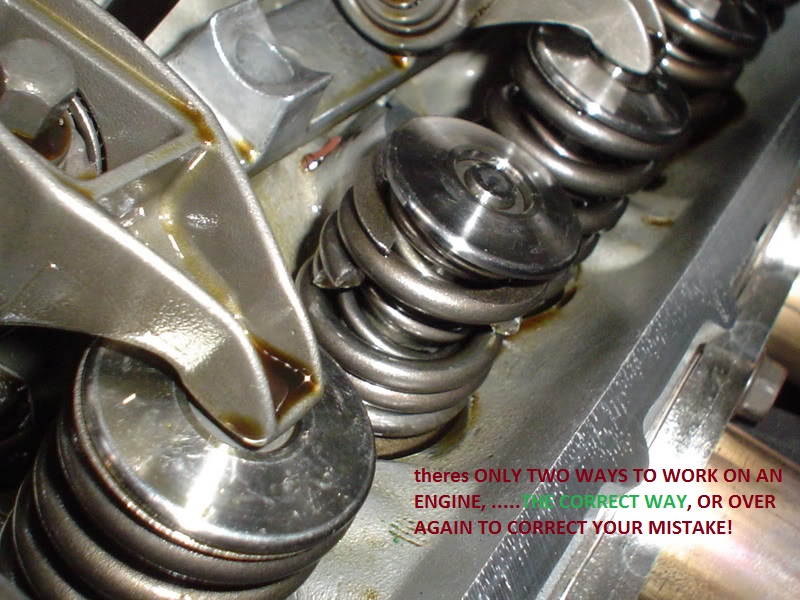
STOP AND ACKNOWLEDGE THE FACT YOU NEED BOTH TOOLS AND KNOWLEDGE,
THAT WILL TAKE TIME AND RESEARCH AND SOME EXPERIENCE,
AS I've stated before, I could have you watch me build a kick-ass race engine and then let you try and duplicate the effort, the problem is not in your new found skills its in the fact it takes decades to look over the fit finish and condition of components to know what needs to be tested, clearances required and what might need in depth testing or extensive machine work, and because every last combo will have different requirements you would not have acquired ALL the skills and EXPERIENCE NEEDED,YOU WILL NEED TO DO EXTENSIVE RESEARCH, and the fact is that, until you have had several dozen engine builds in your past, and have acquired several thousand dollars in tools and made dozens of reliable contacts in machine shops and parts supply houses. and made plenty of minor mistakes in the process!
now that in no way means you can.t build a decent engine on the first try, IF your willing to take things slowly , think logically and ask questions and do a good deal of reading!
have you ever taken the time, and effort,
too step back and grab a legal pad and pen, and logically make a reasonably complete list of the parts you,ll need,
and do the research required too list every part, (including all the small components like bolts, bearings gaskets) and their current cost, where you can find those components for sale, and part number, brand and supplier, and the phone numbers etc.
and call a local machine shop to get a better idea as to the labor cost of a project your looking into starting?
once you do theres commonly three things youll face,
the first is generally a sense of being over whelmed and depressed at the un-expected,total projected cost!
the second is a very common and strong temptation to either scrap the whole idea or to start substituting cheaper and generally considerably lower quality components that in the long run will eventually make the completed project either not worth owning and certainly something your less than proud to own.
and the third is the strong tendency to purchase parts that you find for bargain priced that either are not well matched to the intended projects goals, or nearly useless when matched to the project goals, but the bargain price seems nearly impossible to pass on.
all these tendency's result in a great many partly complete or abandoned projects, or projects that don,t resemble anything close to the original intent, or projects that never get started in the first place.
the completion of a well designed project will take some detailed planing and the ability to stick with the original projects part list and goals, and doing your research in detail, as to both the parts and machine shop costs, the time required and in many cases the tools that you might need,and of course youll need a place to work and store the project while its being built or repaired, well before you start buying components
http://www.themotorbookstore.com/resmchstvi.html
http://www.amazon.com/Lingenfelter-Modi ... 82&sr=8-11"]Amazon.com: John Lingenfelter on Modifying Small-block Chevy Engines (0075478012381): John Lingenfelter: Books
http://www.amazon.com/Smokey-Yunicks-Po ... 809&sr=8-2"]Amazon.com: Smokey Yunick's Power Secrets (9780931472060): Smokey Yunick: Books
http://www.summitracing.com/popup/calcsandtools/stroker-combinations
http://garage.grumpysperformance.com/index.php?threads/rod-bolt-mics-stretch-gauges.989/
http://www.airflowresearch.com/articles/SBC/biggerbetter/big.php
(hit cancel the info appears)
https://www.dragzine.com/news/engine-machining-101-getting-started-with-your-engine-build/
http://garage.grumpysperformance.co...ty-thats-key-in-building-a-good-engine.11682/
http://www.hotrod.com/how-to/engine...-assembly-for-a-stroker-383-chevrolet-engine/
buy these book/video's its probably the best money value you can get, you might be amazed at what a couple hours research into the subject will do to help you build a much more durable engine, and actually reading thru links and sub-links and asking questions helps a great deal
http://www.bracketmasters.com/small_blo ... 383_cu.htm
http://www.circletrack.com/enginetech/1 ... education/
HERES A FEW GENERAL TIPS
http://www.powerperformancenews.com/fea ... ve-longer/
milling stroker clearance on 350/383

 www.motortrend.com
viewtopic.php?f=51&t=7697&p=26187#p26187
http://www.chevyhiperformance.com/tech/ ... clearance/
http://www.carcraft.com/techarticles/cc ... ewall.html
http://garage.grumpysperformance.com/index.php?threads/torque-specs-calculator-links-etc.1222/
http://www.small-block-chevy.com/assemblyspec.html
youll need a decent value in a less expensive yet stable engine stand
http://www.northerntool.com/shop/tools/ ... _200305217
all these threads add useful info on your parts selection
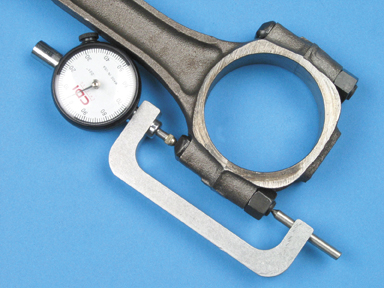
you'll
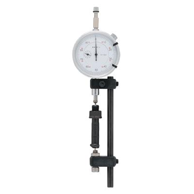
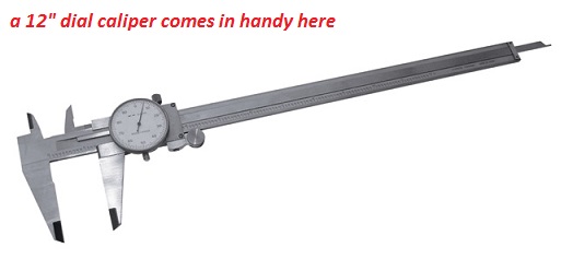
need accurate precision measuring tools
http://garage.grumpysperformance.com/index.php?threads/precision-measuring-tools.1390/
http://www.maintenanceresources.com/ref ... alance.htm
http://www.circletrack.com/enginetech/c ... rminology/
http://www.flatlanderracing.com/probe-sportsbc04.html
http://www.flatlanderracing.com/probe-sportsbc04.html
viewtopic.php?f=69&t=2378&p=6279&hilit=hemi#p6279
http://www.technovelocity.com/chevyhack ... cation.htm
I know some of you guys would rather pluck your eye out with a red hot fork, rather than read links and sub links but for the few who want to learn...
http://www.carcraft.com/techarticles/cc ... index.html
http://garage.grumpysperformance.com/index.php?threads/replacing-a-gen1-rear-main-seal.474/#post-585
here high lights, or cliff note version
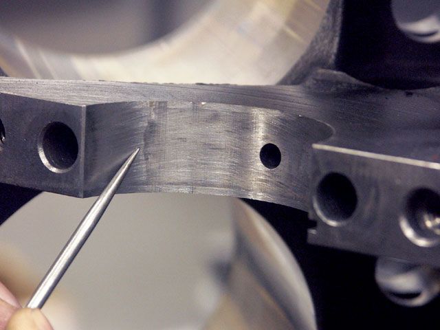
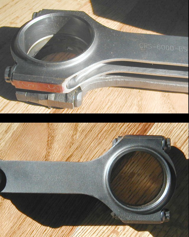
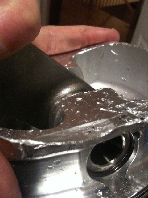
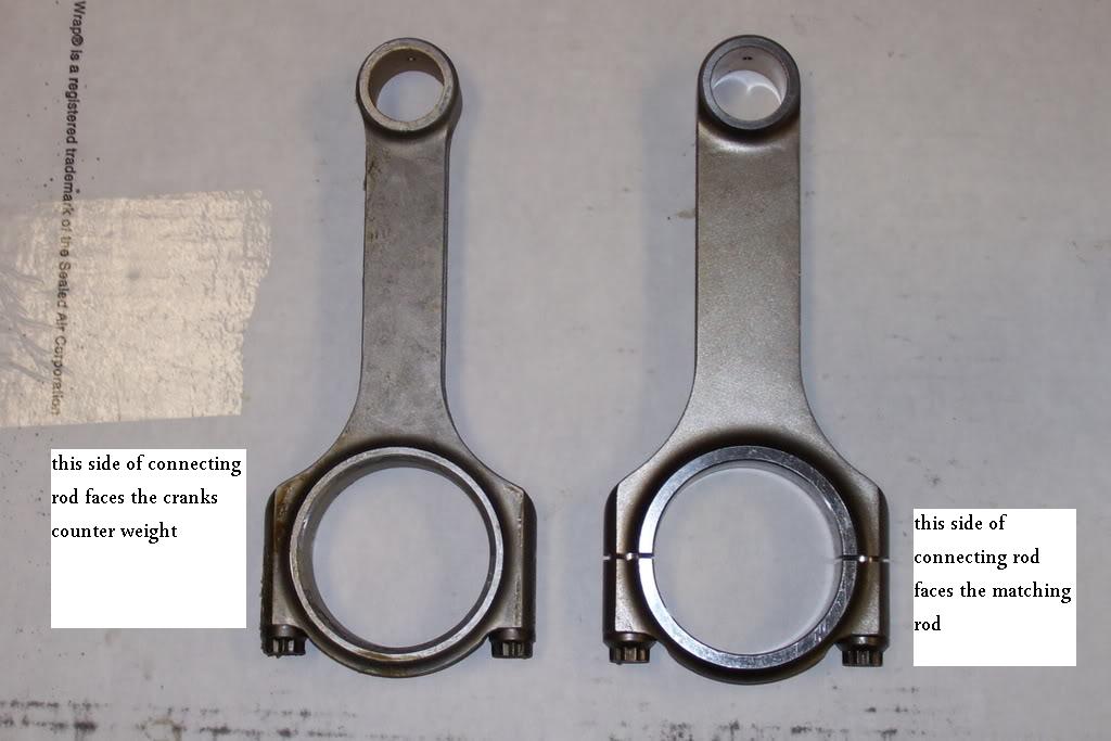
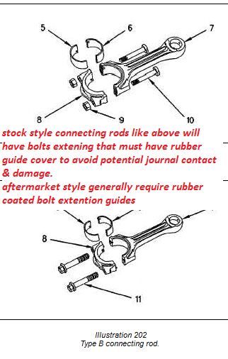
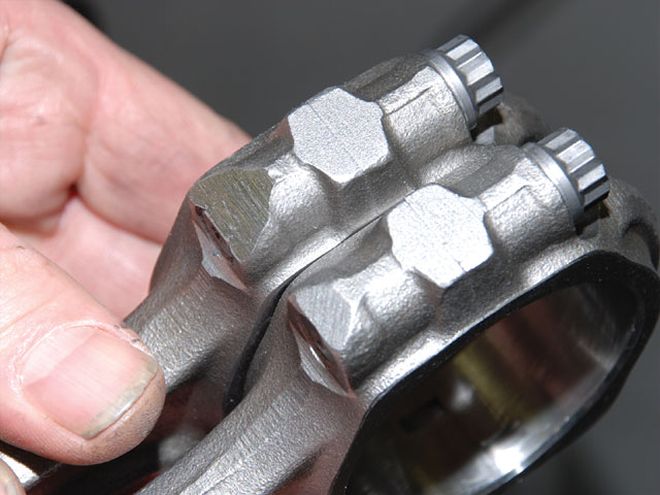
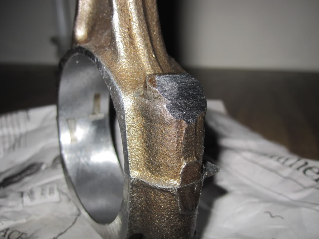
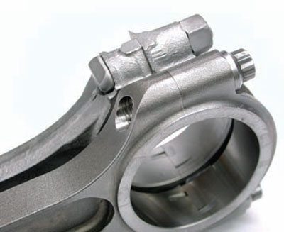
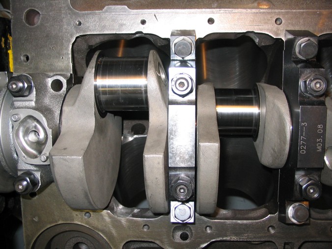
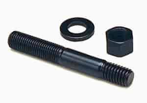
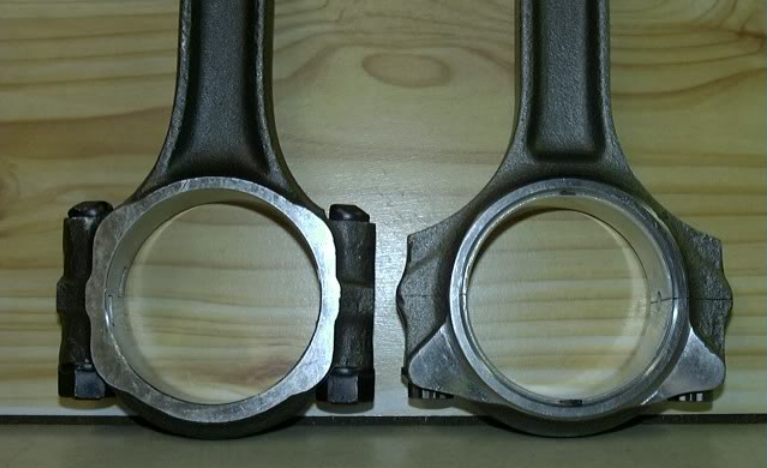
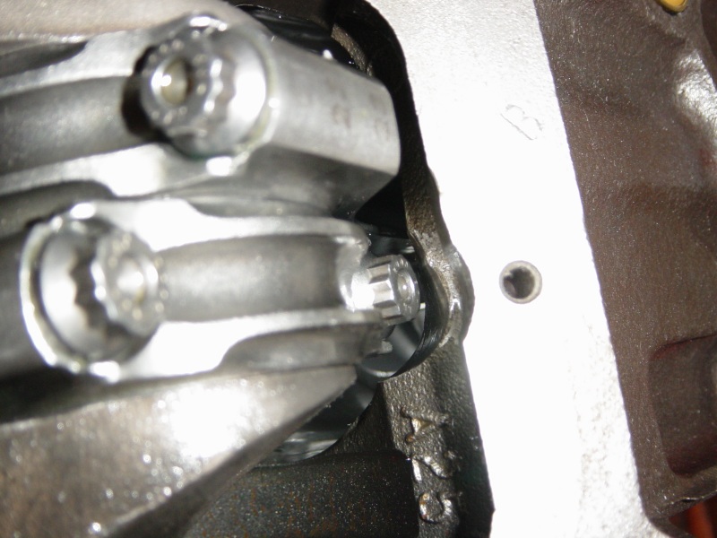
rods that use bolts with nuts like pictured below will be weakened if excessively clearance ground
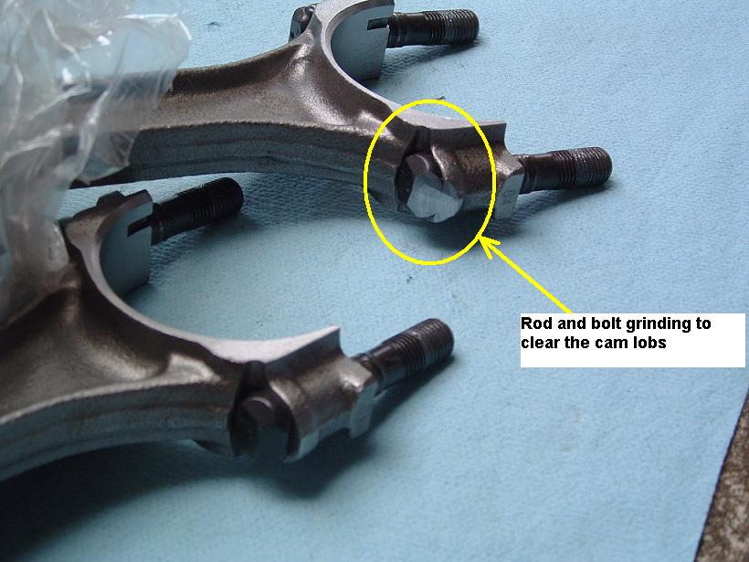
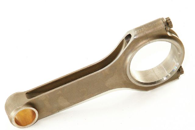
stroker profile rods offer more clearance to cam lobes, and yes the stroker clearanced profile rods are available in both (h) and (I ) beam designs

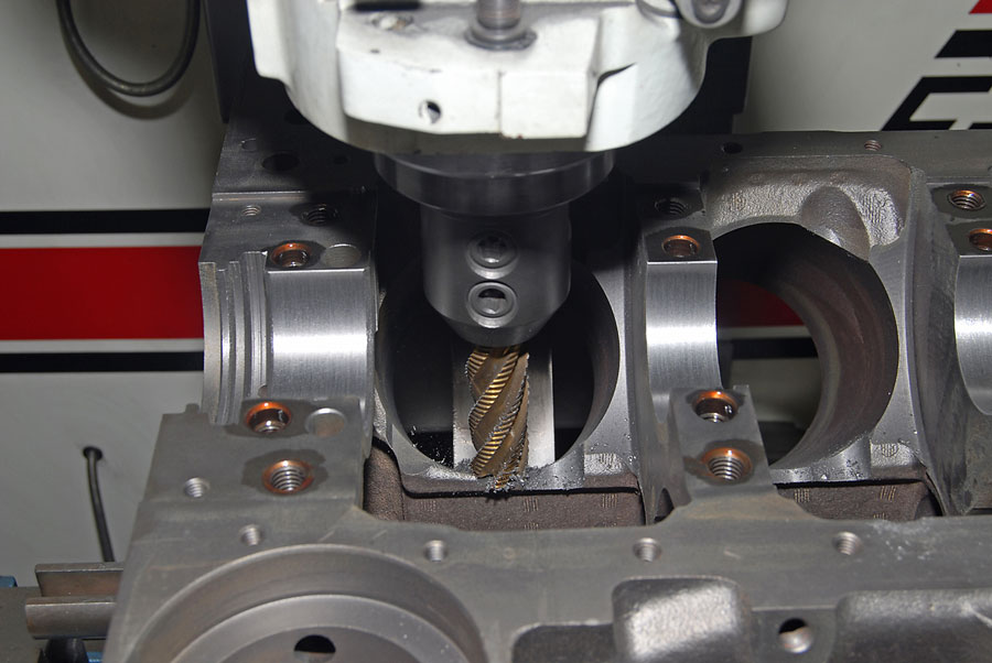
generally its a minor easily done clearance job
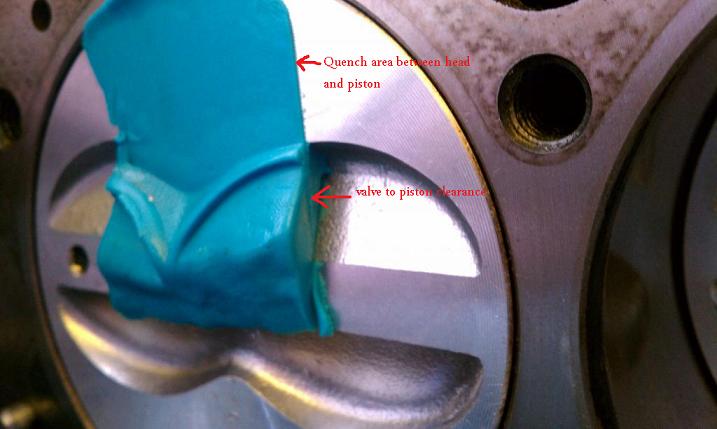
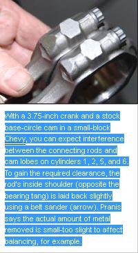
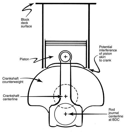
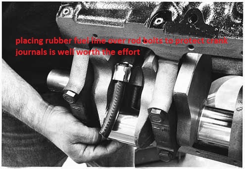
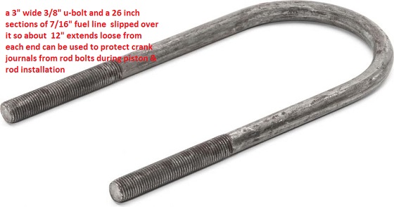
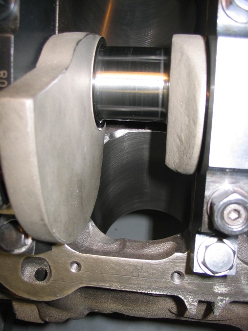
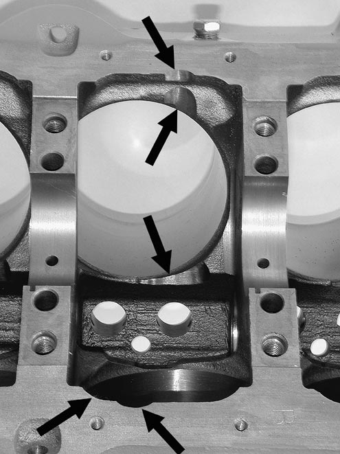
place a single rod/piston assembly with well oiled bearings and use no rings installed on the piston,in the first cylinders bore , be sure the crank journal,has old bearings well greased in the rod your using to get the clearances and have the cam installed to check clearances, also, you don,t necessarily need to degree it in, correctly a dot-to-dot install on the cam will give you a good idea on clearance work. ,now, rotate the crank thru a couple full rotations so the piston slides freely in the oiled bore, while you look closely at the rod too block clearance and rod too cam lobe clearance, if the cam lobes are too close the edge of the rod bolt upper/edge ( no less than .080 thousands, is ideal) of the rod bolt or the rod itself needs to be filed/ground for clearance since you can,t grind the cam lobe, on the block the block gets clearances ground, you want about a .060 minimum clearance. a large paper clip can be used as a crude feeler gauge,
a 1/2" diam carbide cutting burr in a die grinder can do it in seconds,once that's done you move that piston & rod to the next cylinder and repeat 7 more times, etc. don,t forget to clean up afterward,with both a strong magnet, and a pressure washer and solvent or at least high pressure air, and DON,T forget the rod and piston has the exhaust/intake valve and rod bearing radius fit correctly in only one direction on that cylinder, so youll need two rods/pistons, a left and a right for the clearance work,
read the links
http://www.chevymania.com/tech/383.htm
http://www.hotrod.com/how-to/engine/ccrp-0808-383-stroker-small-block-chevy/
http://www.hotrod.com/howto/69883_strok ... index.html
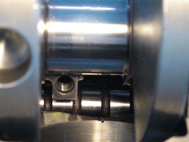
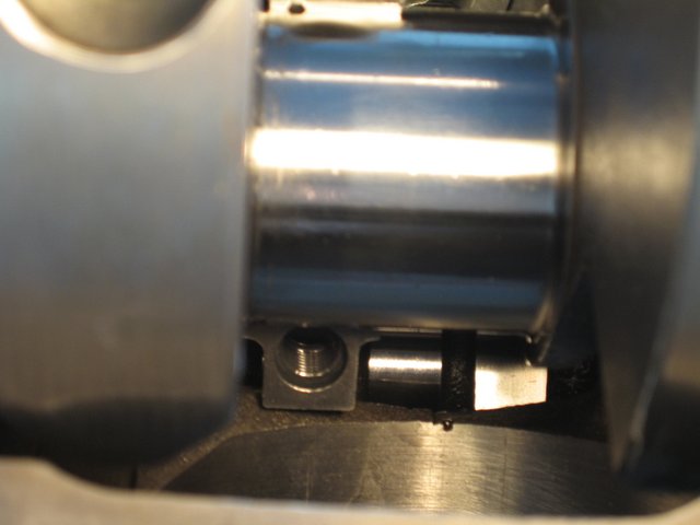
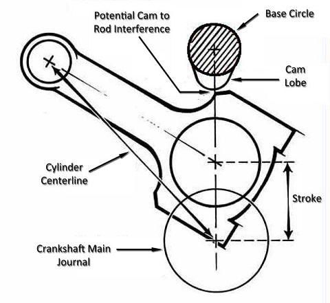
notice how the rod bolts come close to the cam bearings and cam lobes,as the pistons reach top dead canter in the bores, this clearance must be individually checked and should be no less than about .060 (generally you cam use a LARGE plastic tie-wrap
https://www.amazon.com/BuyCableTies...D=41U9CtmwOuL&preST=_SY300_QL70_&dpSrc=detail
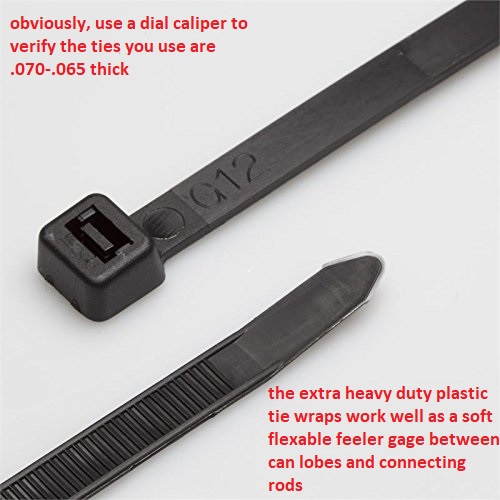
placed between the cam lobe and connecting rod bolts or connecting rod shoulder areas to check clearances as the soft tie-wrap will not damage the cam lobe while you verify clearances)you must install the timing set and index the cam correctly to get a valid clearance , as the cam lobes rotate and at some point they can be incorrectly indexed too hit the rods, while they would not if correctly timed.
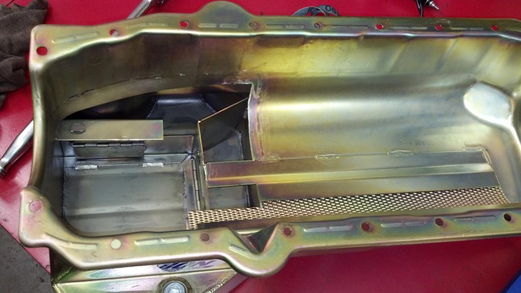
use a good 7-8 quart baffled oil pan
keep in mind the (H) style rods and the CAP SCREW designs generally have more clearance than the stock bolt/nut design rods, and theres are stroker rods designed for max clearance
AFTER
some of the newer stroker rods do in most cases let you avoid the use of a smaller base circle cam, but because there's dozens of different connecting rod designs and different types of rods and rod bolts clearances vary a good deal,
as alway you'll need to check & verify the clearances, once the cam is degreed in, and rods are installed in your particular engine.
 www.chevydiy.com
 www.chevydiy.com
 www.motortrend.com
http://garage.grumpysperformance.com/index.php?threads/bearings-and-oil-flow.150/#post-68205
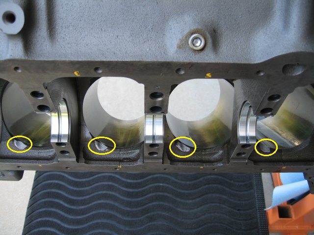
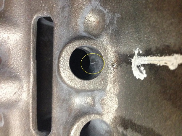
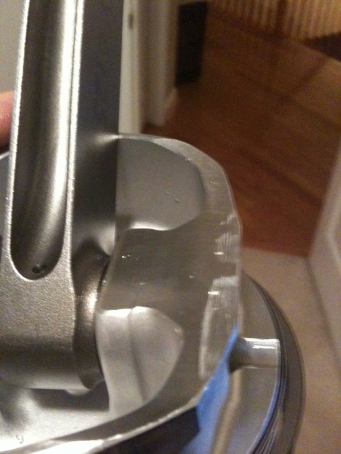
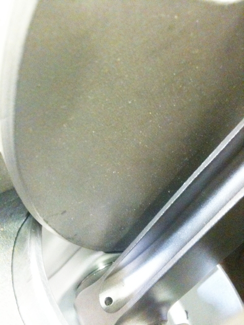
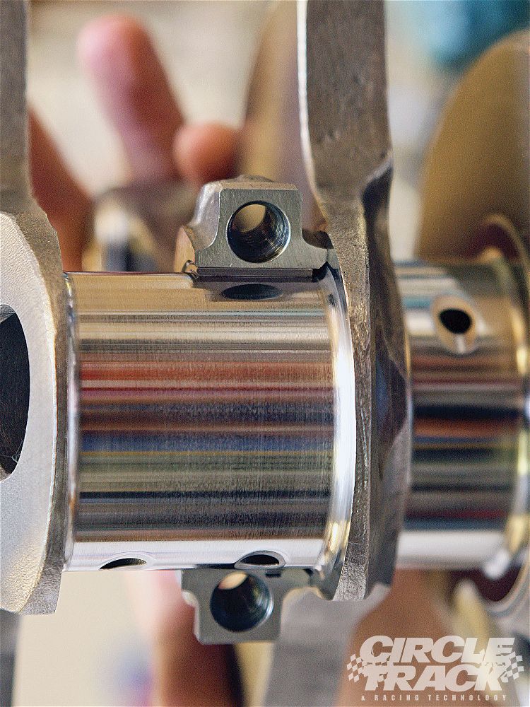
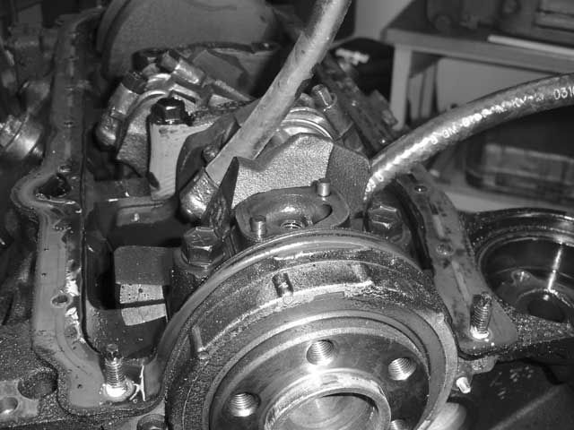
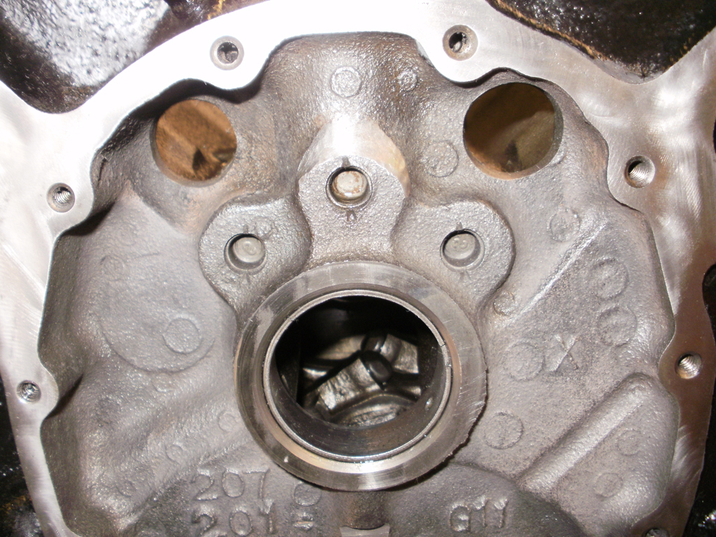
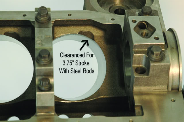
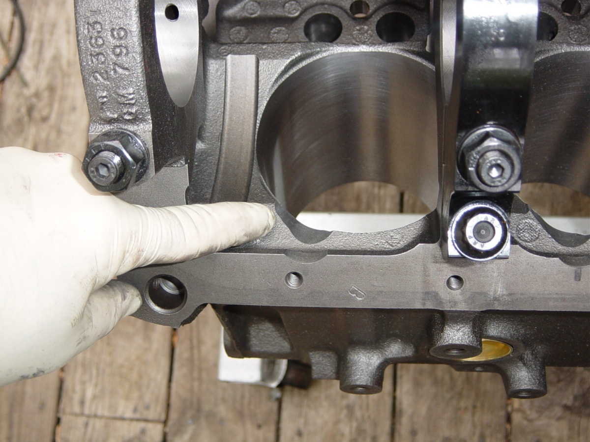
when building a 383 stroker ,you need to check rod to cam and rod to block clearances, you should have not problem grinding .080 or so clearance on the lower bore wall edge with zero chance of getting into the water jacket passages or water jacket at the area of the yellow paint indicated in that picture, most people forget to check that area
obviously youll want to check all 8 cylinders and remove the cam and clean carefully before re-installing the cam.
Small Chevy
Fastener Type Torque Spec
7/16 in. outer main cap bolt 65 ft.-lbs.
7/16 in. inner main cap bolt 70 ft.-lbs.
3/8 in. outer main cap bolt 40 ft.-lbs.
11/32 in. connecting rod bolt 38-44 ft.-lbs.
3/8 in. connecting rod bolt 40-45 ft.-lbs.
Cylinder head bolts 65 ft.-lbs.
Screw-in rocker arm studs 50 ft.-lbs.
Intake manifold bolts (cast iron heads) 30 ft.-lbs.
Oil pump bolt 60-70 ft.-lbs.
Cam sprocket bolts 18-20 ft.-lbs.
Harmonic damper bolt 60 ft.-lbs.
Flywheel/Flexplate bolts 65 ft.-lbs.
Pressure plate bolts 35 ft.-lbs.
Bell housing bolts 25 ft.-lbs.
Exhaust manifold bolts 25 ft.-lbs.
http://www.precisionenginetech.com/tech ... ch-part-1/
http://www.precisionenginetech.com/tech ... ch-part-2/
Big Chevy
Fastener Type Torque Specs
Main cap bolt, 396-427 2-bolt 95 ft.-lbs.
Main cap bolt, 396-454 4-bolt (inner/outer) 110 ft.-lbs.
3/8 in. connecting rod bolt 50 ft.-lbs.
7/16 in. connecting rod bolt 67-73 ft.-lbs.
Cylinder head bolts, long 75 ft.-lbs.
Cylinder head bolts, short 65-68 ft.-lbs.
Screw-in rocker arm studs 50 ft.-lbs.
Intake manifold bolts (cast iron head) 25 ft.-lbs.
Oil pump bolt 65 ft.-lbs.
Cam sprocket bolts 20 ft.-lbs.
Harmonic damper bolt 85 ft.-lbs.
Flywheel/Flexplate bolts 60 ft.-lbs.
Pressure plate bolts 35 ft.-lbs.
Bell housing bolts 25 ft.-lbs.
Exhaust manifold bolts 20 ft.-lbs.


http://www.fourwheeler.com/techarticles/128_9712_chevy_engine_specifications/photo_11.html
IF your going to use ARP main cap studs THE TORQUE SETTINGS ARE DIFFERENT than the original BOLTS, the STUDS ARE STRONGER, BUT,you might also consider that main studs generally install after cleaning the threads in the block with a tap,blowing them dry with high pressure air, oiling the studs course threads with the thread sealant and fine threads end with the ARP thread lube, when you screw them into the block the full thread depth,by hand, then get backed out one turn, the main caps installed and the nuts torqued in stages to seat and hold the main caps, now LOOK at those STUDS the end in the block threads is SAE COURSE thread, the end your torquing the nut on is SAE FINE THREAD with a much differant PITCH that requires less tq to give the same clamp loads
AND yes it very common for the stroker crank, counter weights or connecting rods in a 383-400 to touch a 350 oil pan, and make a ticking or knocking sound, if you don,t clearance it a bit more, with a ball peen hammer on the oil pan rail area, Id also check the dip stick as some touch the rotating assembly
for obvious interference, youll need to check this, it can be made to clear rather easily but it must be checked and properly fitted/clearanced

http://www.arp-bolts.com/catalog/Catalog.html
Why do they get backed out by one turn? I'm trying to think of the physics behind it, but I can't think of any good reason. What is the physics answer, Grumpy?
the threads must bear evenly and align correctly with the studs center line, for the stud to apply max loads over the total threaded surface ,the threaded section must be under tension alone and engage the total threaded surface in the block, if the stud is torqued into place, you've preloaded the threads bearing the load and they are partly under compressive loads ,your basically jacking the bottom of the threaded hole away from the threaded section, and applying THOUSANDS of lbs of extra stress to the blocks web area if you torque the threads to the same 100 ft lbs the original bolts were tightened to, the threads in the block will now have added stress once the full tension loads on the studs and main caps is applied by torquing the nuts on the studs ,theres added stress on the block, if the studs have bottomed out and are pushing on the bottom of the threaded hole making the block web area more likely to crack or the crank saddles to distort.
keep in mind FACTORY BOLTS are made slightly shorter to PREVENT the bolt tip bottoming out in the hole, but bolts cause wear on the threads because they are tightened while the bolts still advancing deeper into the threaded block, studs cause far less wear because they fully engage the threads bearing the loads before the tensive load is applied
heres what ARP says
"STUDS vs. BOLTS
ARP recommends the use of main studs over bolts whenever possible for several key reasons. First is the ability to obtain more accurate torque readings because studs don’t “twist†into the block. All clamping forces are on one axis. By the same token, there is less force exerted on the block threads, which contributes to improved block life (very critical on aluminum blocks). Finally, there are factors of easier engine assembly and proper alignment of caps every time"
ARP's instructions (for head studs)state that you should thread the studs into the block until they're hand-tight, but with the head on the block, this is difficult. Fortunately, ARP was thoughtful enough to incorporate a fitting for an Allen wrench into the head of each stud. So, using an Allen wrench, I threaded the studs into the head until I could no longer turn the wrench with two fingers. This method seems to have worked nicely
1. Clean and chase appropriate threads in
block to ensure proper thread engagement
and accurate torque readings.
2. All hardware (and caps) should be
cleaned and inspected prior to installation,
looking for any shipping damage or defects.
3. Screw studs into block, finger tight
ONLY. For permanent installation, apply
Loc-tite (or similar adhesive) sparingly
to threads. Be sure and install the caps
promptly before the cement sets to prevent
misalignment of studs in block.
1. Clean and chase appropriate threads in
block to ensure proper thread engagement
and accurate torque readings.
2. All hardware (and caps) should be
cleaned and inspected prior to installation,
looking for any shipping damage or defects.
There are a number of important considerations
when installing ARP main studs.
3. Screw studs into block, finger tight
ONLY. For permanent installation, apply
Loc-tite (or similar adhesive) sparingly
to threads. Be sure and install the caps
promptly before the cement sets to prevent
misalignment of studs in block.
First and foremost is making sure the
block and studs are as clean as possible.
Foreign matter and debris can easily affect
the quality of thread engagement and
cause erroneous torque readings. Do not
re-cut threads in the block – use the special
“chaser†taps as listed on page 87 of this catalog.
This will preserve the integrity of the
threads and provide better engagement.
Calibrate your torque wrench – even new
wrenches have been known to be off by as
much as 10 foot pounds! Use consistent
tightening techniques.
4. Install main caps, checking for binding
and misalignment. Lubricate threads, nuts
and washers with oil or ARP moly assembly
lubricant before installation. Note that torque
specs will vary by lubricant. Moly lube is
most consistent. Have block align honed.
5. Using the instructions provided with
the studs, tighten the nuts to proper
torque values three times. NOTE: If using
Loc-Tite or similar cement, proper preload
must be achieved prior to it setting up.
removing the rod caps during clearance checks while building your 383 ,does seem to allow you to see the clearance issues a bit easier
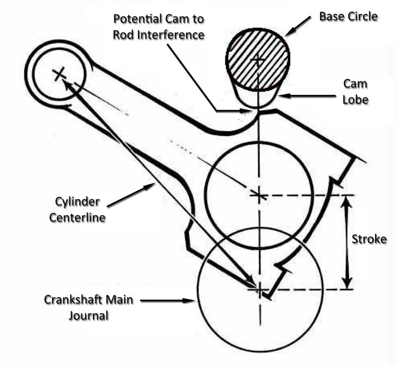
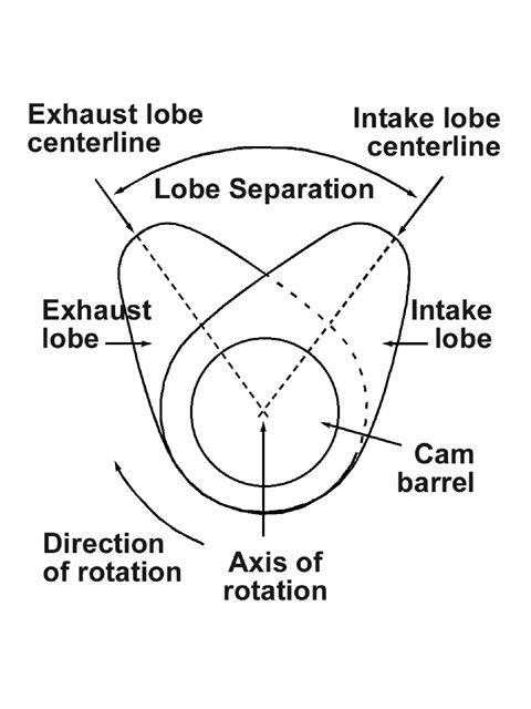
yes the cam lobes can very easily contact the connecting rods when the cam index is out of its proper timing, on almost any chevy engine the cam lobe center lines will be spaced at between 103 and 116 degrees, with the piston at TDC theres SUPPOSED to be about .060 MINIMUM clearance between the connecting rod bolts and cam lobes, this is a mandatory clearance check point and a plastic cable tie can be used to gauge clearance, its best done on each individual connecting rod to cam lobe clearance point AFTER the cams been degreed into the block as each connecting rods being installed but Ive generally done it during the several trial assembly points where I check other clearances like block to connecting rod clearance.
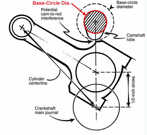
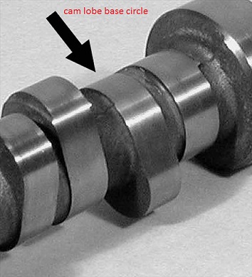
thats why on some stroker crank engines a SMALL BASE CIRCLE cam is used to MAXIMIZE CLEARANCE,between the two moving parts.
a cams lobe lift is the difference the lifter moves off the cams base circle between its base circle and its max lobe lift, thus a cam with a 1.1" diam base circle and a .400 lobe lift would have a , .400 lobe lift and if you had 1.5:1 ratio rockers a .600 valve lift, but if you wanted more clearance you could use a smaller base circle at .900, and a 400 lobe lift this would allow the connecting rod, to sweep by with an additional amount of cam lobe to connecting rod bolt clearance, the change in diameter generally requires a swap to a stronger cam billet core . vs cheaper cast core,to maintain cam strength

the cam rotates while indexed by the timing chain at 1/2 crank shaft speed , there are connecting rods designed to provide additional clearance.
http://www.arp-bolts.com/FAQ/FAQ.html
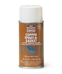
I usually use this sealant (sparingly)on the course ends of main cap studs that screw in hand tight, and ESPECIALLY on head studs that enter water jackets
http://www.permatex.com/products/Au.../Permatex_Super_300_Form-A-Gasket_Sealant.htm

be sure that FLYWHEEL,you select matches the intended application
and it is SFI certified, IDEALLY billet, your feet will thank you,
and ideally, you use a blow proof bell housing, thats a good idea
and I would select a 28 lb-36 lb flywheel,for street use.
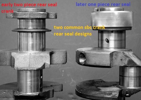
if its the newer sbc single rear seal block.
be sure its for a single rear seal crank,
and they make 153 and 168 tooth gear designs,
you need to match your application, and your bell housing and starter
also be aware there are internal and externally balanced 383 SBC kits and 5.7" and 6" rod kits,
and some that require a neutrally balanced damper and an externally balanced flywheel
https://www.summitracing.com/parts/...MIyrK1kZaY6QIVFP_jBx05Vw71EAQYAyABEgL4HfD_BwE
as usual, there's a ton of related info in the links and sub links
http://garage.grumpysperformance.co...ectly-installing-bellhousings.584/#post-21691
http://garage.grumpysperformance.com/index.php?threads/a-brief-look-at-clutches.447/
http://garage.grumpysperformance.com/index.php?threads/engine-balancing.3900/#post-10338
http://garage.grumpysperformance.com/index.php?threads/selecting-a-flywheel.1042/#post-1945
http://garage.grumpysperformance.com/index.php?threads/harmonic-balancer.3554/#post-9433
http://garage.grumpysperformance.com/index.php?threads/sfi-tested-parts-sources.3011/#post-7917
keep in mind the course thread section is not being screwed in or the threads moved as the nut on the fine thread upper end is torqued to spec. and that thread requires the ARP thread lubricant to get the correct stretch and that stud needs to be cycled up to full torque then released and re torqued,a minimum of three times to get the stretch/tq correct
I got asked recently what hydraulic roller cam ID suggest for a street/strip 383 combo?(obviously theres a wide selection that may work,)
ONE GENTLEMAN pointed out ,after shopping around one of the least expensive deals seems to be the EDELBROCK CAM BELOW
http://www.jegs.com/i/Edelbrock/350/22015/10002/-1#
SB-Chevy 283-400 Hydraulic Roller Camshaft Kit
Duration Advertised 296° Intake/300° Exhaust
Duration @ .050'' 234° Intake/238° Exhaust
Lift @ Valve .539'' Intake/.548'' Exhaust
Lift @ Cam .359'' Intake/.365'' Exhaust
Lobe Separation Angle 112°
Intake Centerline 107°
Intake Timing @ .050" Open 10° BTDC
Close 44° ABDC
Exhaust Timing @ .050" Open 56° BBDC
Close 2° ATDC
IVE used similar cam designs (duration/lift/)in the past with excellent results and $709 for the cam, roller lifters and push rods is a good value, naturally the REST of the components and the cars drive train and the cars intended use will effect the choice
the only thing that makes me hesitate is the quality of edelbrocks cam cores.AS most IVE SEEN are not billet but cast cores which are less durable and on a 383, PLUS you want a small base circle cam......for rotating assembly clearance issues ,one reason I usually suggest this cam in similar combos
roller cams are in most case's potentially, much superior to non-roller cams in that they can,
provide potential greater effective duration and lift, with less friction losses.
(assuming you do your homework and select a well matched cam and components matching the engines requirements, compression, gearing etc.)
but you can't use the same valve springs,on the heads,valve train geometry differes signficantly, push rods are shorter, . as the roller lifter's are taller and heavier, the combo of components required to swap from flat tappet to full roller can become rather expensive, $1000-$1500 easily once you get the valve springs push rods roller lifters, billet cam core and ideally roller rockers.
for that, cost, the added roller valve train and roller rockers, etc. youll generally gain an additional 25-35 added horse power over a similar duration flat tappet version due to more effective volumetric efficierncy and reduced friction.
considering the average
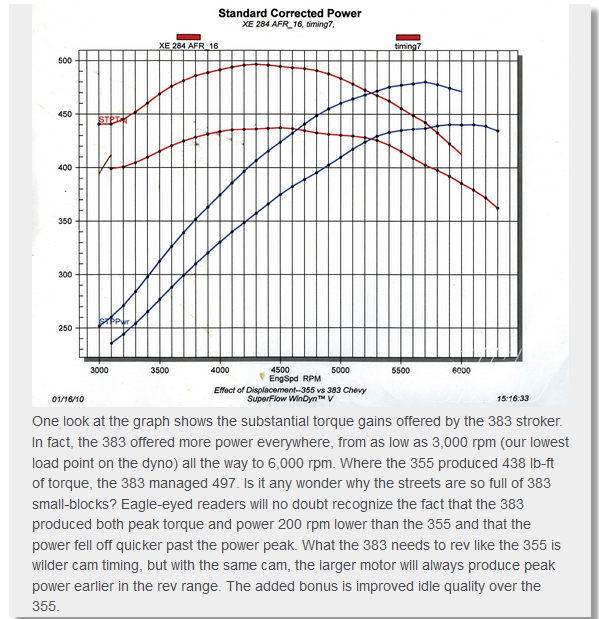
thus its common to get 25-30 hp from a flat tapet performance cam upgrade and maybe 45-65 hp from a roller cam valve train upgrade View attachment 105252
View attachment 105251
View attachment 105253
your cams lift is the result of the lifter movement distance from the cams base circle, where the valves seated to the point where its fully up on the nose of the cam lobe where the valves at full lift.
example
lets say in this case we compare two imaginary cams
a standard cams base circle is 1.125" and
your cams running on a .900 base circle
both cams have a .560 valve lift and run with 1.5:1 rockers
so both cams will need to move the lifter .374"
that means the standard cam lobe will be 1.125"+.374" or 1.499" from the cams base to the cam lobe nose
that means the small base cam lobe will be .900"+.374" or 1.274" from the cams base to the cam lobe nose
which is significantly smaller
http://www.cranecams.com/index.php?show=browseParts&action=partSpec&partNumber=119661&lvl=2&prt=5
http://www.jegs.com/i/Crane/270/119661/10002/-1#
http://www.jegs.com/webapp/wcs/stores/servlet/KeywordSearchCmd?storeId=10001&catalogId=10002&langId=-1&N=0&Ntt=11532-16&Ntk=all&Nty=1&D=11532-16&Ntx=mode+matchallany&Dx=mode+matchallany&searchTerm=11532-16
Grind Number: HR-230/359-2S-12.90 IG
Operating Range: 3000-6500 RPM
Duration Advertised: 292° Intake / 300° Exhaust
Duration @ .050'' Lift: 230° Intake / 238° Exhaust
Valve Lift w/1.5 Rockers: .539'' Intake / .558'' Exhaust
Lobe Separation Angle: 112°
Max Lift Angle: 107° ATDC Intake / 117° BTDC Exhaust
Open/Close @.050'' Cam Lift: Intake - 8° BTDC (opens) / 42° ABDC (closes)
Exhaust - 56° BBDC (opens) / 2° ATDC (closes)
with either cam you'll want a 3000rpm stall converter , about 10.5:1 cpr and a 3.73-4.11:1 rear gear to maximize the performance and a low restriction exhaust, headers and a high flow intake
IM currently running the crane 119661 cam in MY 383 and Ive tested over a dozen cams in that engine, so if its a street/strip combo ID suggest going that route, SMALL BASE CIRCLE AND BILLET CORE.....yeah! YOU GET WHAT YOU PAY,FOR and DURABILITY FOR PARTS TENDS TO COST MORE
BTW
IVE dunked my piston/ring assembly's in a can of MARVEL MYSTERY OIL just before installation with a ring compressor and have never seen the slightest indication of problems either on ring sealing getting the rings broken in, or on tearing the engines down later for inspections
remember that when you go to re-install the compressed piston rings, and piston in the engine block,bores that dunking the piston in MARVEL MYSTERY OIL , just before, its slid into the ring compressor will coat the rings and bore contact areas enough to prevent many small problems that insufficient lube might case
THAT WILL TAKE TIME AND RESEARCH AND SOME EXPERIENCE,
AS I've stated before, I could have you watch me build a kick-ass race engine and then let you try and duplicate the effort, the problem is not in your new found skills its in the fact it takes decades to look over the fit finish and condition of components to know what needs to be tested, clearances required and what might need in depth testing or extensive machine work, and because every last combo will have different requirements you would not have acquired ALL the skills and EXPERIENCE NEEDED,YOU WILL NEED TO DO EXTENSIVE RESEARCH, and the fact is that, until you have had several dozen engine builds in your past, and have acquired several thousand dollars in tools and made dozens of reliable contacts in machine shops and parts supply houses. and made plenty of minor mistakes in the process!
now that in no way means you can.t build a decent engine on the first try, IF your willing to take things slowly , think logically and ask questions and do a good deal of reading!
have you ever taken the time, and effort,
too step back and grab a legal pad and pen, and logically make a reasonably complete list of the parts you,ll need,
and do the research required too list every part, (including all the small components like bolts, bearings gaskets) and their current cost, where you can find those components for sale, and part number, brand and supplier, and the phone numbers etc.
and call a local machine shop to get a better idea as to the labor cost of a project your looking into starting?
once you do theres commonly three things youll face,
the first is generally a sense of being over whelmed and depressed at the un-expected,total projected cost!
the second is a very common and strong temptation to either scrap the whole idea or to start substituting cheaper and generally considerably lower quality components that in the long run will eventually make the completed project either not worth owning and certainly something your less than proud to own.
and the third is the strong tendency to purchase parts that you find for bargain priced that either are not well matched to the intended projects goals, or nearly useless when matched to the project goals, but the bargain price seems nearly impossible to pass on.
all these tendency's result in a great many partly complete or abandoned projects, or projects that don,t resemble anything close to the original intent, or projects that never get started in the first place.
the completion of a well designed project will take some detailed planing and the ability to stick with the original projects part list and goals, and doing your research in detail, as to both the parts and machine shop costs, the time required and in many cases the tools that you might need,and of course youll need a place to work and store the project while its being built or repaired, well before you start buying components
http://www.themotorbookstore.com/resmchstvi.html
http://www.amazon.com/Lingenfelter-Modi ... 82&sr=8-11"]Amazon.com: John Lingenfelter on Modifying Small-block Chevy Engines (0075478012381): John Lingenfelter: Books
http://www.amazon.com/Smokey-Yunicks-Po ... 809&sr=8-2"]Amazon.com: Smokey Yunick's Power Secrets (9780931472060): Smokey Yunick: Books
http://www.summitracing.com/popup/calcsandtools/stroker-combinations
http://garage.grumpysperformance.com/index.php?threads/rod-bolt-mics-stretch-gauges.989/
http://www.airflowresearch.com/articles/SBC/biggerbetter/big.php
(hit cancel the info appears)
https://www.dragzine.com/news/engine-machining-101-getting-started-with-your-engine-build/
http://garage.grumpysperformance.co...ty-thats-key-in-building-a-good-engine.11682/
flex hone
hi grumpy I cant seem to find the forums that talk about using a flex hone and procedures on using one? needs some guidance thanks
garage.grumpysperformance.com
http://www.hotrod.com/how-to/engine...-assembly-for-a-stroker-383-chevrolet-engine/
buy these book/video's its probably the best money value you can get, you might be amazed at what a couple hours research into the subject will do to help you build a much more durable engine, and actually reading thru links and sub-links and asking questions helps a great deal
http://www.bracketmasters.com/small_blo ... 383_cu.htm
http://www.circletrack.com/enginetech/1 ... education/
HERES A FEW GENERAL TIPS
http://www.powerperformancenews.com/fea ... ve-longer/
milling stroker clearance on 350/383
Stealth TPI Induction - L98 Stroker Installation - Super Chevy Magazine
This Chevrolet L98 TPI engine has its displacement stroked to 383 cubic inches and has stealth mods installed including a new cam and an extrude honed tuned port injection system to make 458 HP - Super Chevy Magazine
viewtopic.php?f=51&t=7697&p=26187#p26187
http://www.chevyhiperformance.com/tech/ ... clearance/
http://www.carcraft.com/techarticles/cc ... ewall.html
http://garage.grumpysperformance.com/index.php?threads/torque-specs-calculator-links-etc.1222/
http://www.small-block-chevy.com/assemblyspec.html
youll need a decent value in a less expensive yet stable engine stand
http://www.northerntool.com/shop/tools/ ... _200305217
all these threads add useful info on your parts selection
you'll
need accurate precision measuring tools
http://garage.grumpysperformance.com/index.php?threads/precision-measuring-tools.1390/
Valve Spring Cooling via Engine Oil
Grumpy: Read your post on the subject of Valve Spring Cooling with Engine Oil. Thanks VERY MUCH for bringing this to my attention. I have built a SBC 383 stroker going into a 1971 Datsun 240Z. Used a shaft rocker setup, but am uncertain that the trunion is being lubricated via Engine Oil...
garage.grumpysperformance.com
http://www.maintenanceresources.com/ref ... alance.htm
http://www.circletrack.com/enginetech/c ... rminology/
http://www.flatlanderracing.com/probe-sportsbc04.html
http://www.flatlanderracing.com/probe-sportsbc04.html
viewtopic.php?f=69&t=2378&p=6279&hilit=hemi#p6279
http://www.technovelocity.com/chevyhack ... cation.htm
I know some of you guys would rather pluck your eye out with a red hot fork, rather than read links and sub links but for the few who want to learn...
http://www.carcraft.com/techarticles/cc ... index.html
http://garage.grumpysperformance.com/index.php?threads/replacing-a-gen1-rear-main-seal.474/#post-585
here high lights, or cliff note version
rods that use bolts with nuts like pictured below will be weakened if excessively clearance ground
stroker profile rods offer more clearance to cam lobes, and yes the stroker clearanced profile rods are available in both (h) and (I ) beam designs
generally its a minor easily done clearance job
place a single rod/piston assembly with well oiled bearings and use no rings installed on the piston,in the first cylinders bore , be sure the crank journal,has old bearings well greased in the rod your using to get the clearances and have the cam installed to check clearances, also, you don,t necessarily need to degree it in, correctly a dot-to-dot install on the cam will give you a good idea on clearance work. ,now, rotate the crank thru a couple full rotations so the piston slides freely in the oiled bore, while you look closely at the rod too block clearance and rod too cam lobe clearance, if the cam lobes are too close the edge of the rod bolt upper/edge ( no less than .080 thousands, is ideal) of the rod bolt or the rod itself needs to be filed/ground for clearance since you can,t grind the cam lobe, on the block the block gets clearances ground, you want about a .060 minimum clearance. a large paper clip can be used as a crude feeler gauge,
a 1/2" diam carbide cutting burr in a die grinder can do it in seconds,once that's done you move that piston & rod to the next cylinder and repeat 7 more times, etc. don,t forget to clean up afterward,with both a strong magnet, and a pressure washer and solvent or at least high pressure air, and DON,T forget the rod and piston has the exhaust/intake valve and rod bearing radius fit correctly in only one direction on that cylinder, so youll need two rods/pistons, a left and a right for the clearance work,
read the links
http://www.chevymania.com/tech/383.htm
http://www.hotrod.com/how-to/engine/ccrp-0808-383-stroker-small-block-chevy/
http://www.hotrod.com/howto/69883_strok ... index.html
notice how the rod bolts come close to the cam bearings and cam lobes,as the pistons reach top dead canter in the bores, this clearance must be individually checked and should be no less than about .060 (generally you cam use a LARGE plastic tie-wrap
https://www.amazon.com/BuyCableTies...D=41U9CtmwOuL&preST=_SY300_QL70_&dpSrc=detail
placed between the cam lobe and connecting rod bolts or connecting rod shoulder areas to check clearances as the soft tie-wrap will not damage the cam lobe while you verify clearances)you must install the timing set and index the cam correctly to get a valid clearance , as the cam lobes rotate and at some point they can be incorrectly indexed too hit the rods, while they would not if correctly timed.
use a good 7-8 quart baffled oil pan
keep in mind the (H) style rods and the CAP SCREW designs generally have more clearance than the stock bolt/nut design rods, and theres are stroker rods designed for max clearance
AFTER
some of the newer stroker rods do in most cases let you avoid the use of a smaller base circle cam, but because there's dozens of different connecting rod designs and different types of rods and rod bolts clearances vary a good deal,
as alway you'll need to check & verify the clearances, once the cam is degreed in, and rods are installed in your particular engine.
Big-Inch Chevy Small-Block Cheat Sheet: Connecting Rods
Big-Inch Chevy Small-Block Cheat Sheet: Connecting Rods- Step by Step How-To Instructions, Images, Examples, and Checklists
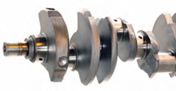
Chevy Small Block Cranks, Rods, and Piston Guide
Chevy Small Block Cranks, Rods, and Piston Guide- How to Build Max Performance Chevy Small Blocks on a Budget
383 Stroker Small Block Chevy - Car Craft Magazine
A 383 Stroker Small Block Chevy is analyzed, assembled and dynoed. Follow along and get every fact and trick you wanted to know about a 383 build. - Car Craft Magazine
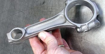
should you re-use stock connecting rods?
I get asked all the time, "should you re-use those stock rods, when I rebuild my 350 or when I build my 383 stroker" or "Ive got a 325hp 396 BBC,Im rebuilding, should I upgrade or rebuild the connecting rods" most sbc and many BBC stock rods are designed to be cheap, and dependable in engines...
garage.grumpysperformance.com
http://garage.grumpysperformance.com/index.php?threads/bearings-and-oil-flow.150/#post-68205
when building a 383 stroker ,you need to check rod to cam and rod to block clearances, you should have not problem grinding .080 or so clearance on the lower bore wall edge with zero chance of getting into the water jacket passages or water jacket at the area of the yellow paint indicated in that picture, most people forget to check that area
obviously youll want to check all 8 cylinders and remove the cam and clean carefully before re-installing the cam.
Small Chevy
Fastener Type Torque Spec
7/16 in. outer main cap bolt 65 ft.-lbs.
7/16 in. inner main cap bolt 70 ft.-lbs.
3/8 in. outer main cap bolt 40 ft.-lbs.
11/32 in. connecting rod bolt 38-44 ft.-lbs.
3/8 in. connecting rod bolt 40-45 ft.-lbs.
Cylinder head bolts 65 ft.-lbs.
Screw-in rocker arm studs 50 ft.-lbs.
Intake manifold bolts (cast iron heads) 30 ft.-lbs.
Oil pump bolt 60-70 ft.-lbs.
Cam sprocket bolts 18-20 ft.-lbs.
Harmonic damper bolt 60 ft.-lbs.
Flywheel/Flexplate bolts 65 ft.-lbs.
Pressure plate bolts 35 ft.-lbs.
Bell housing bolts 25 ft.-lbs.
Exhaust manifold bolts 25 ft.-lbs.
http://www.precisionenginetech.com/tech ... ch-part-1/
http://www.precisionenginetech.com/tech ... ch-part-2/
Big Chevy
Fastener Type Torque Specs
Main cap bolt, 396-427 2-bolt 95 ft.-lbs.
Main cap bolt, 396-454 4-bolt (inner/outer) 110 ft.-lbs.
3/8 in. connecting rod bolt 50 ft.-lbs.
7/16 in. connecting rod bolt 67-73 ft.-lbs.
Cylinder head bolts, long 75 ft.-lbs.
Cylinder head bolts, short 65-68 ft.-lbs.
Screw-in rocker arm studs 50 ft.-lbs.
Intake manifold bolts (cast iron head) 25 ft.-lbs.
Oil pump bolt 65 ft.-lbs.
Cam sprocket bolts 20 ft.-lbs.
Harmonic damper bolt 85 ft.-lbs.
Flywheel/Flexplate bolts 60 ft.-lbs.
Pressure plate bolts 35 ft.-lbs.
Bell housing bolts 25 ft.-lbs.
Exhaust manifold bolts 20 ft.-lbs.
http://www.fourwheeler.com/techarticles/128_9712_chevy_engine_specifications/photo_11.html
IF your going to use ARP main cap studs THE TORQUE SETTINGS ARE DIFFERENT than the original BOLTS, the STUDS ARE STRONGER, BUT,you might also consider that main studs generally install after cleaning the threads in the block with a tap,blowing them dry with high pressure air, oiling the studs course threads with the thread sealant and fine threads end with the ARP thread lube, when you screw them into the block the full thread depth,by hand, then get backed out one turn, the main caps installed and the nuts torqued in stages to seat and hold the main caps, now LOOK at those STUDS the end in the block threads is SAE COURSE thread, the end your torquing the nut on is SAE FINE THREAD with a much differant PITCH that requires less tq to give the same clamp loads
AND yes it very common for the stroker crank, counter weights or connecting rods in a 383-400 to touch a 350 oil pan, and make a ticking or knocking sound, if you don,t clearance it a bit more, with a ball peen hammer on the oil pan rail area, Id also check the dip stick as some touch the rotating assembly
for obvious interference, youll need to check this, it can be made to clear rather easily but it must be checked and properly fitted/clearanced
http://www.arp-bolts.com/catalog/Catalog.html
Why do they get backed out by one turn? I'm trying to think of the physics behind it, but I can't think of any good reason. What is the physics answer, Grumpy?
the threads must bear evenly and align correctly with the studs center line, for the stud to apply max loads over the total threaded surface ,the threaded section must be under tension alone and engage the total threaded surface in the block, if the stud is torqued into place, you've preloaded the threads bearing the load and they are partly under compressive loads ,your basically jacking the bottom of the threaded hole away from the threaded section, and applying THOUSANDS of lbs of extra stress to the blocks web area if you torque the threads to the same 100 ft lbs the original bolts were tightened to, the threads in the block will now have added stress once the full tension loads on the studs and main caps is applied by torquing the nuts on the studs ,theres added stress on the block, if the studs have bottomed out and are pushing on the bottom of the threaded hole making the block web area more likely to crack or the crank saddles to distort.
keep in mind FACTORY BOLTS are made slightly shorter to PREVENT the bolt tip bottoming out in the hole, but bolts cause wear on the threads because they are tightened while the bolts still advancing deeper into the threaded block, studs cause far less wear because they fully engage the threads bearing the loads before the tensive load is applied
heres what ARP says
"STUDS vs. BOLTS
ARP recommends the use of main studs over bolts whenever possible for several key reasons. First is the ability to obtain more accurate torque readings because studs don’t “twist†into the block. All clamping forces are on one axis. By the same token, there is less force exerted on the block threads, which contributes to improved block life (very critical on aluminum blocks). Finally, there are factors of easier engine assembly and proper alignment of caps every time"
ARP's instructions (for head studs)state that you should thread the studs into the block until they're hand-tight, but with the head on the block, this is difficult. Fortunately, ARP was thoughtful enough to incorporate a fitting for an Allen wrench into the head of each stud. So, using an Allen wrench, I threaded the studs into the head until I could no longer turn the wrench with two fingers. This method seems to have worked nicely
1. Clean and chase appropriate threads in
block to ensure proper thread engagement
and accurate torque readings.
2. All hardware (and caps) should be
cleaned and inspected prior to installation,
looking for any shipping damage or defects.
3. Screw studs into block, finger tight
ONLY. For permanent installation, apply
Loc-tite (or similar adhesive) sparingly
to threads. Be sure and install the caps
promptly before the cement sets to prevent
misalignment of studs in block.
1. Clean and chase appropriate threads in
block to ensure proper thread engagement
and accurate torque readings.
2. All hardware (and caps) should be
cleaned and inspected prior to installation,
looking for any shipping damage or defects.
There are a number of important considerations
when installing ARP main studs.
3. Screw studs into block, finger tight
ONLY. For permanent installation, apply
Loc-tite (or similar adhesive) sparingly
to threads. Be sure and install the caps
promptly before the cement sets to prevent
misalignment of studs in block.
First and foremost is making sure the
block and studs are as clean as possible.
Foreign matter and debris can easily affect
the quality of thread engagement and
cause erroneous torque readings. Do not
re-cut threads in the block – use the special
“chaser†taps as listed on page 87 of this catalog.
This will preserve the integrity of the
threads and provide better engagement.
Calibrate your torque wrench – even new
wrenches have been known to be off by as
much as 10 foot pounds! Use consistent
tightening techniques.
4. Install main caps, checking for binding
and misalignment. Lubricate threads, nuts
and washers with oil or ARP moly assembly
lubricant before installation. Note that torque
specs will vary by lubricant. Moly lube is
most consistent. Have block align honed.
5. Using the instructions provided with
the studs, tighten the nuts to proper
torque values three times. NOTE: If using
Loc-Tite or similar cement, proper preload
must be achieved prior to it setting up.
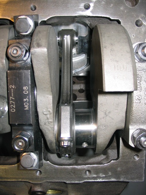
removing the rod caps during clearance checks while building your 383 ,does seem to allow you to see the clearance issues a bit easier
yes the cam lobes can very easily contact the connecting rods when the cam index is out of its proper timing, on almost any chevy engine the cam lobe center lines will be spaced at between 103 and 116 degrees, with the piston at TDC theres SUPPOSED to be about .060 MINIMUM clearance between the connecting rod bolts and cam lobes, this is a mandatory clearance check point and a plastic cable tie can be used to gauge clearance, its best done on each individual connecting rod to cam lobe clearance point AFTER the cams been degreed into the block as each connecting rods being installed but Ive generally done it during the several trial assembly points where I check other clearances like block to connecting rod clearance.
thats why on some stroker crank engines a SMALL BASE CIRCLE cam is used to MAXIMIZE CLEARANCE,between the two moving parts.
a cams lobe lift is the difference the lifter moves off the cams base circle between its base circle and its max lobe lift, thus a cam with a 1.1" diam base circle and a .400 lobe lift would have a , .400 lobe lift and if you had 1.5:1 ratio rockers a .600 valve lift, but if you wanted more clearance you could use a smaller base circle at .900, and a 400 lobe lift this would allow the connecting rod, to sweep by with an additional amount of cam lobe to connecting rod bolt clearance, the change in diameter generally requires a swap to a stronger cam billet core . vs cheaper cast core,to maintain cam strength
the cam rotates while indexed by the timing chain at 1/2 crank shaft speed , there are connecting rods designed to provide additional clearance.
http://www.arp-bolts.com/FAQ/FAQ.html
I usually use this sealant (sparingly)on the course ends of main cap studs that screw in hand tight, and ESPECIALLY on head studs that enter water jackets
http://www.permatex.com/products/Au.../Permatex_Super_300_Form-A-Gasket_Sealant.htm
be sure that FLYWHEEL,you select matches the intended application
and it is SFI certified, IDEALLY billet, your feet will thank you,
and ideally, you use a blow proof bell housing, thats a good idea
and I would select a 28 lb-36 lb flywheel,for street use.
if its the newer sbc single rear seal block.
be sure its for a single rear seal crank,
and they make 153 and 168 tooth gear designs,
you need to match your application, and your bell housing and starter
also be aware there are internal and externally balanced 383 SBC kits and 5.7" and 6" rod kits,
and some that require a neutrally balanced damper and an externally balanced flywheel
https://www.summitracing.com/parts/...MIyrK1kZaY6QIVFP_jBx05Vw71EAQYAyABEgL4HfD_BwE
as usual, there's a ton of related info in the links and sub links
http://garage.grumpysperformance.co...ectly-installing-bellhousings.584/#post-21691
http://garage.grumpysperformance.com/index.php?threads/a-brief-look-at-clutches.447/
http://garage.grumpysperformance.com/index.php?threads/engine-balancing.3900/#post-10338
http://garage.grumpysperformance.com/index.php?threads/selecting-a-flywheel.1042/#post-1945
http://garage.grumpysperformance.com/index.php?threads/harmonic-balancer.3554/#post-9433
http://garage.grumpysperformance.com/index.php?threads/sfi-tested-parts-sources.3011/#post-7917
keep in mind the course thread section is not being screwed in or the threads moved as the nut on the fine thread upper end is torqued to spec. and that thread requires the ARP thread lubricant to get the correct stretch and that stud needs to be cycled up to full torque then released and re torqued,a minimum of three times to get the stretch/tq correct
I got asked recently what hydraulic roller cam ID suggest for a street/strip 383 combo?(obviously theres a wide selection that may work,)
ONE GENTLEMAN pointed out ,after shopping around one of the least expensive deals seems to be the EDELBROCK CAM BELOW
http://www.jegs.com/i/Edelbrock/350/22015/10002/-1#
SB-Chevy 283-400 Hydraulic Roller Camshaft Kit
Duration Advertised 296° Intake/300° Exhaust
Duration @ .050'' 234° Intake/238° Exhaust
Lift @ Valve .539'' Intake/.548'' Exhaust
Lift @ Cam .359'' Intake/.365'' Exhaust
Lobe Separation Angle 112°
Intake Centerline 107°
Intake Timing @ .050" Open 10° BTDC
Close 44° ABDC
Exhaust Timing @ .050" Open 56° BBDC
Close 2° ATDC
IVE used similar cam designs (duration/lift/)in the past with excellent results and $709 for the cam, roller lifters and push rods is a good value, naturally the REST of the components and the cars drive train and the cars intended use will effect the choice
the only thing that makes me hesitate is the quality of edelbrocks cam cores.AS most IVE SEEN are not billet but cast cores which are less durable and on a 383, PLUS you want a small base circle cam......for rotating assembly clearance issues ,one reason I usually suggest this cam in similar combos
roller cams are in most case's potentially, much superior to non-roller cams in that they can,
provide potential greater effective duration and lift, with less friction losses.
(assuming you do your homework and select a well matched cam and components matching the engines requirements, compression, gearing etc.)
but you can't use the same valve springs,on the heads,valve train geometry differes signficantly, push rods are shorter, . as the roller lifter's are taller and heavier, the combo of components required to swap from flat tappet to full roller can become rather expensive, $1000-$1500 easily once you get the valve springs push rods roller lifters, billet cam core and ideally roller rockers.
for that, cost, the added roller valve train and roller rockers, etc. youll generally gain an additional 25-35 added horse power over a similar duration flat tappet version due to more effective volumetric efficierncy and reduced friction.
considering the average
thus its common to get 25-30 hp from a flat tapet performance cam upgrade and maybe 45-65 hp from a roller cam valve train upgrade View attachment 105252
View attachment 105251
View attachment 105253
is a roller cam worth the extra cost vs a flat tappet design
heres some info from COMP CAMS " Flat Tappet vs. Roller Tappet Lifters theres far more than just the cam and lifters required to swap types of cams, if your engines currently equipped with a flat tappet cam your almost sure to need a new timing chain set cam button new push rods obviously a new...
garage.grumpysperformance.com
cast roller cams and high spring pressures don't generally work well
running a cast core roller cam on the street with significantly more than MINIMAL spring pressures for the intended application, IS JUST asking for valve train problems, but a balance must be maintained, if the valve spring is too weak and allows the cam lobe to throw or loft the lifter at...
garage.grumpysperformance.com
sellecting valve springs, and setting up the valve train
How do you determine the spring pressure needed to keep the valves under control for a given lift, duration, and max rpm. It might take you several hours to read thru all the links and sub links but its time very well spent as it could save your engine from destruction and save you thousands of...
garage.grumpysperformance.com
cam wear,articles you need to read
before, you start reading through the thread and links below, Ill point out that I've done the forensics on quite a few failed cams over the years, that guys have brought to my shop and Id say about 60% of the failed cam lobe & lifter problems were traced to a failure to check clearances or...
garage.grumpysperformance.com
example
lets say in this case we compare two imaginary cams
a standard cams base circle is 1.125" and
your cams running on a .900 base circle
both cams have a .560 valve lift and run with 1.5:1 rockers
so both cams will need to move the lifter .374"
that means the standard cam lobe will be 1.125"+.374" or 1.499" from the cams base to the cam lobe nose
that means the small base cam lobe will be .900"+.374" or 1.274" from the cams base to the cam lobe nose
which is significantly smaller
http://www.cranecams.com/index.php?show=browseParts&action=partSpec&partNumber=119661&lvl=2&prt=5
http://www.jegs.com/i/Crane/270/119661/10002/-1#
http://www.jegs.com/webapp/wcs/stores/servlet/KeywordSearchCmd?storeId=10001&catalogId=10002&langId=-1&N=0&Ntt=11532-16&Ntk=all&Nty=1&D=11532-16&Ntx=mode+matchallany&Dx=mode+matchallany&searchTerm=11532-16
Grind Number: HR-230/359-2S-12.90 IG
Operating Range: 3000-6500 RPM
Duration Advertised: 292° Intake / 300° Exhaust
Duration @ .050'' Lift: 230° Intake / 238° Exhaust
Valve Lift w/1.5 Rockers: .539'' Intake / .558'' Exhaust
Lobe Separation Angle: 112°
Max Lift Angle: 107° ATDC Intake / 117° BTDC Exhaust
Open/Close @.050'' Cam Lift: Intake - 8° BTDC (opens) / 42° ABDC (closes)
Exhaust - 56° BBDC (opens) / 2° ATDC (closes)
with either cam you'll want a 3000rpm stall converter , about 10.5:1 cpr and a 3.73-4.11:1 rear gear to maximize the performance and a low restriction exhaust, headers and a high flow intake
IM currently running the crane 119661 cam in MY 383 and Ive tested over a dozen cams in that engine, so if its a street/strip combo ID suggest going that route, SMALL BASE CIRCLE AND BILLET CORE.....yeah! YOU GET WHAT YOU PAY,FOR and DURABILITY FOR PARTS TENDS TO COST MORE
BTW
IVE dunked my piston/ring assembly's in a can of MARVEL MYSTERY OIL just before installation with a ring compressor and have never seen the slightest indication of problems either on ring sealing getting the rings broken in, or on tearing the engines down later for inspections
remember that when you go to re-install the compressed piston rings, and piston in the engine block,bores that dunking the piston in MARVEL MYSTERY OIL , just before, its slid into the ring compressor will coat the rings and bore contact areas enough to prevent many small problems that insufficient lube might case
Last edited by a moderator: