12 volt conversion - ammeter wiring

FishFry

Active Member
Did a 12 volt conversion to my 41, and want to keep the original ammeter.
And yes I know - volt gauge would be better/your car will be on fire etc. - I discussed this ad nauseam, and I understand it.

Point is: I'm not just throwing in a 3 wire alternator and call it a day, I make a complete new harness, since the old one is a mess of a spaghetti monster anyway.
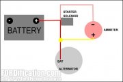
I got an 10 gauge wire going from the alternator to the buss bar (my starter in that case) acting as some kind of shunt that takes most of the load, and "splice" the ammeter in like in this diagram I found.

Does that diagram make any sense to somebody who is more electric savvy then me?

Thanks, Frank
 

Attachments

  • ammeter-schematic.jpg
    ammeter-schematic.jpg
    12 KB · Views: 3
That drawing is a little vague. An ammeter is wired is series with the battery
so it can measure current entering or leaving.

This drawing is alot more detailed.
If you want the PDF file click on the link below.


Amp Gauge Wiring

1) Always disconnect the ground lead from the vehicle battery before wiring any gauge.
2) Classic Instruments’ Amp gauge should only be used on vehicles with alternators rated at 60 Amps or
less. Using an alternator with higher output capacity is dangerous and could cause a fire. A Volt gauge
is available for systems using alternators rated higher than 60 amps.
3) The Amp gauge was designed to be wired in SERIES with the vehicles electrical system. In order to
show proper discharge, all electricity to the vehicle needs to pass through the amp gauge. In order to
show proper charge, all electricity from the alternator / generator needs to pass through the amp gauge.
4) Connect a minimum 10AWG wire from the “BAT” position of the ignition switch to terminal “S” on
the back of the amp gauge.
5) Connect a minimum 10AWG wire from the Alternator “OUTPUT” to terminal “S” of the amp gauge.
6) Connect a minimum 10AWG wire from the “+12V” terminal of the starter solenoid to terminal “I” on
the back of the gauge.
7) Connect a good ground to terminal “G” on the back of the gauge (the ground is only used for the gauge
light).
8) Connect dash light power to the spade connector “L” on the back of the gauge.

IMPORTANT: DO NOT allow any ground wire or other ground to contact either the “I” or “S” terminal of
the amp gauge at any time! A ground contact to these terminals could result in major electrical damage, fire to
your wiring harness, damage to other electrical components, or damage to your car.

1669477078032.png
.
 
Thanks, but putting all that power of an 60 amp alternator through my 30 amp pre war ammeter is what I wanted to avoid.
That's why I planned to use a shunt - pretty much like Ford and GM did in the early 60s.

Frank
 
OK, I didn't fully follow what you were trying to do.

Still your drawing does not look right, electrically your original drawing and the modified drawing are the same. No current would flow thru the meter. So when I say it's vague, that's because I have to assume that the Black dot I added is where the red and pink wires come together. Which is no different then if you connected it where the arrow is instead.

Maybe if you could find a better drawing from the 60's ?

Ammeter01.jpg

Adding a shunt to the drawing below is an option, but a resistor would be about 1/2 Ohm and rated
for 500 watts. That kind of resistor is very expensive. Sorry I can't be of more help !

Ammeter02.jpg
 
Back
Top