heres a bit of a head scratcher issue I have on my 1996 corvette I could use help with, some fuse or relay or sensor failed very recently,
and finding it is making me a bit nuts, the only trouble code that came up indicated the cooling fan relay was defective,

I changed all three cooling fan, relays, checked the fuses and fuse-able links,
but this failed to clear the problem, so Im obviously over looking something here gentlemen?
this will obviously be something I should have spotted easily but at this moment Im overlooking it!
Ive pulled codes several times and it shows no further codes.
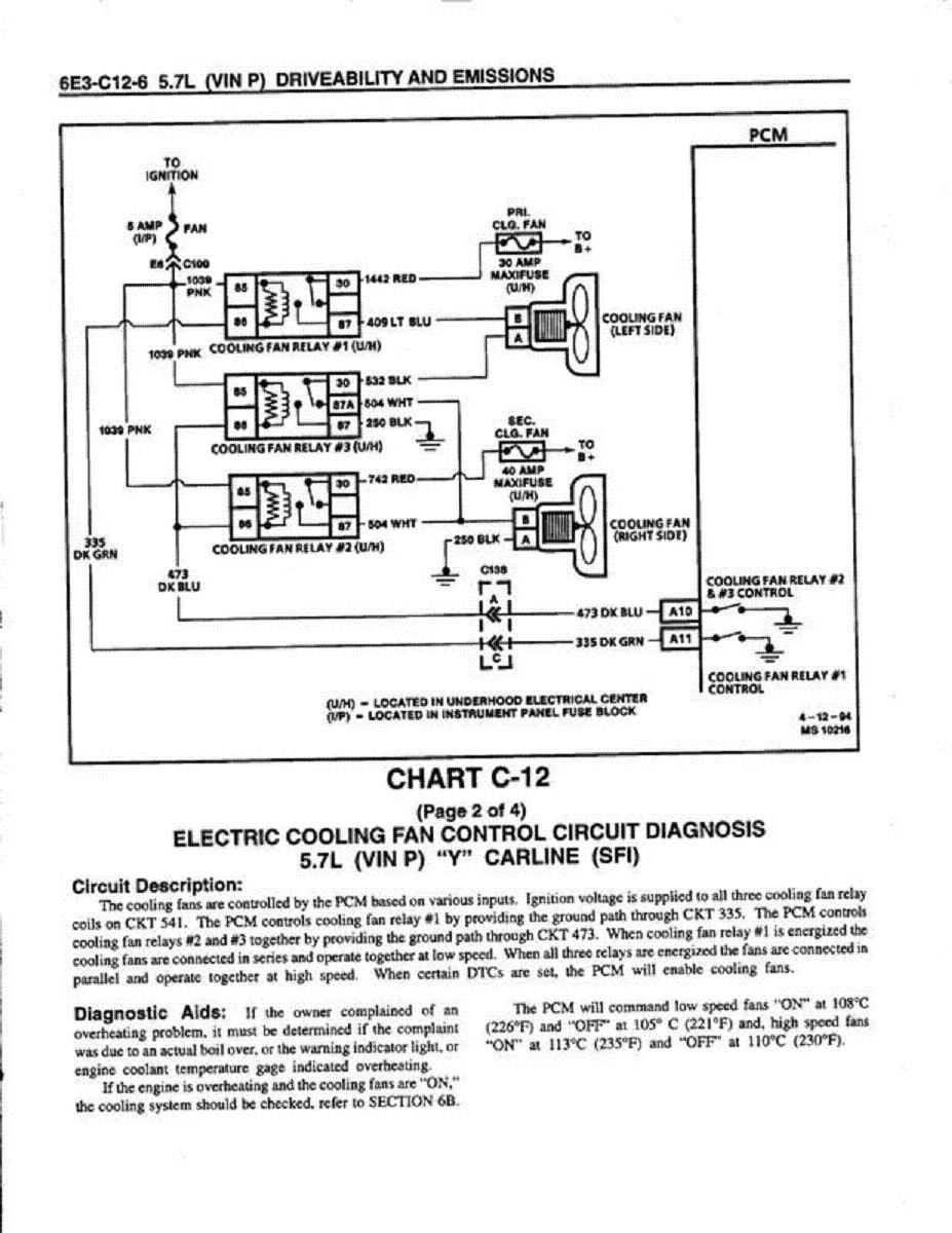
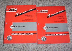
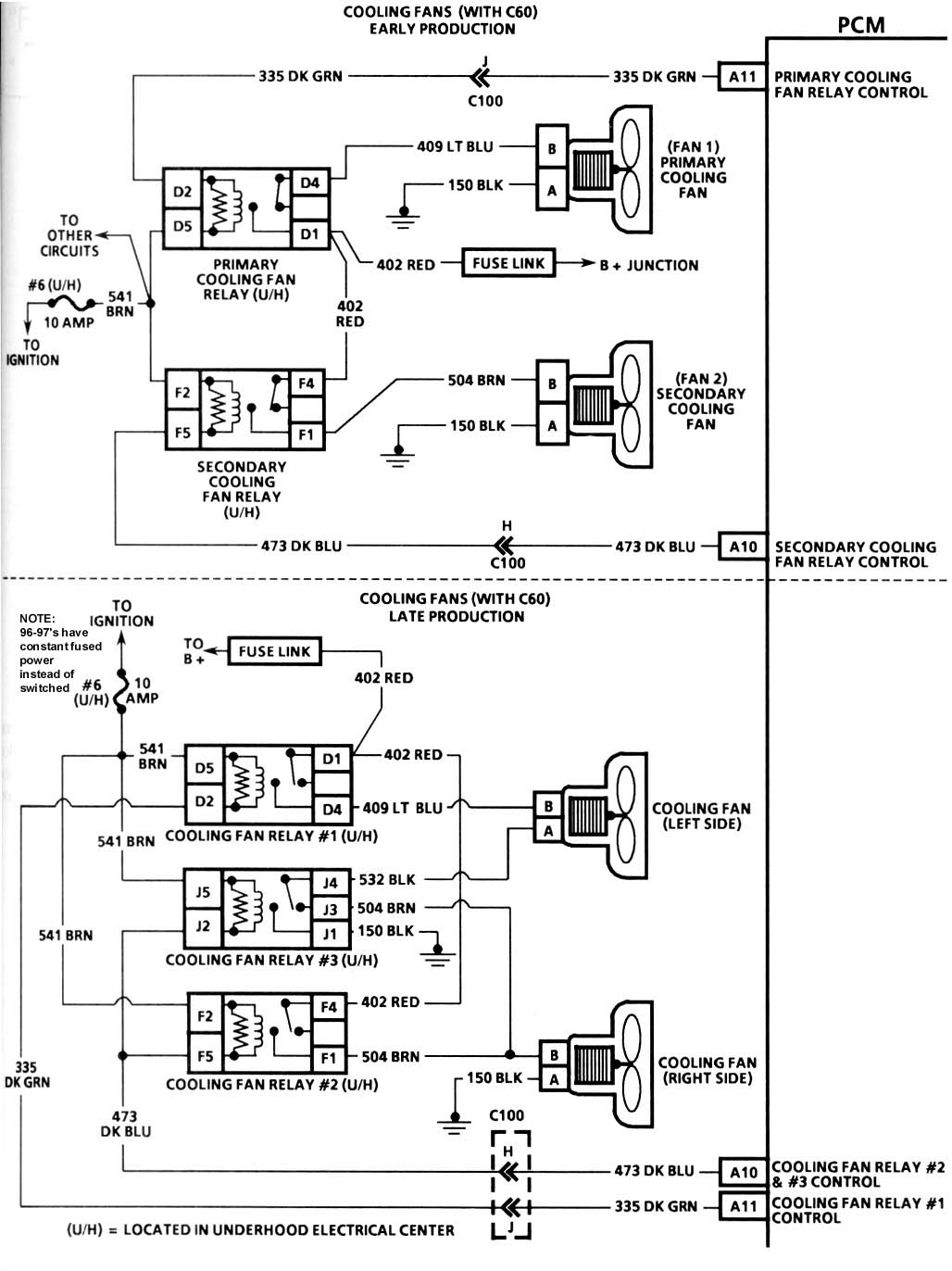
DTC P1641 FC Relay 1 Control Circuit description is located in book #2 Page 6-599 of the service manual. For the cooling fan schematic, refer to Fan Control Circuits
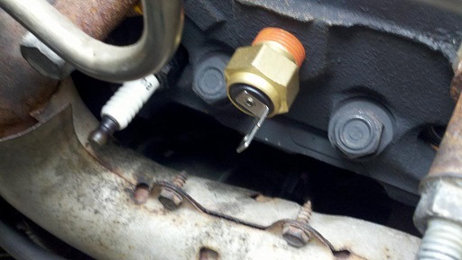
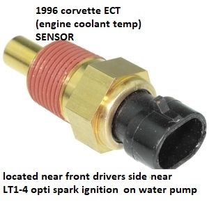
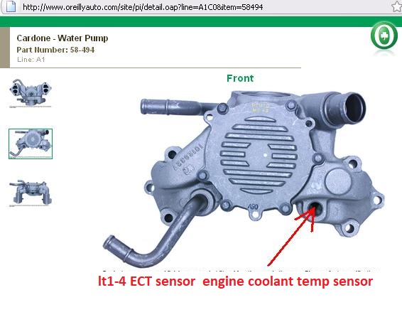
Ive changed the engine temp sensor on the front and on the pass side head
and the trouble code is now gone but the
radiator fans still won,t turn on yet both fans test perfectly fine, and work if I just apply battery
all fuses test good
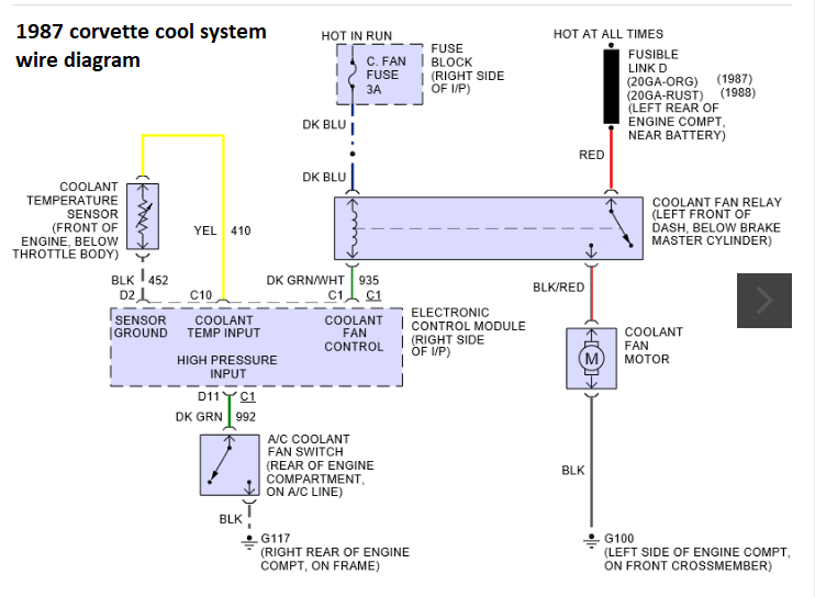
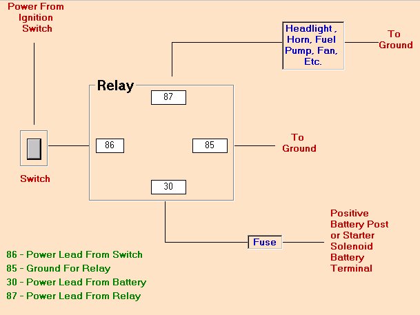
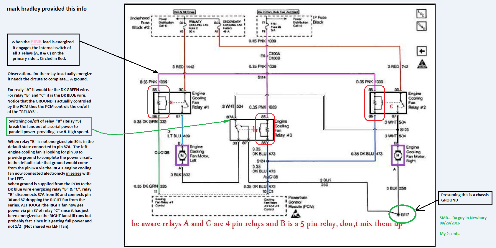
There are three cooling fan relays...And three fuses...Lets begin with the fuses...Fuse #2 (30A)= primary cooling fan...Fuse # 5 (40A)=secondary cooling fan...Both of these are under-hood. Fuse #29 (5A)=fan fuse...Feeds power to all three relays and is located inside...If all three fuses are good; Lets check the relays..All 3 relays receive power on a Pink wire multiple from fuse#29...Ground is fired to pull relay #2 and #3 on a Dark Blue wire from the PCM C1 pin# 10...Relay #1 receives ground from PCM C1 pin#10 on the Dark Green wire...
https://www.ecklers.com/corvette/co...MIjKCGpePe3gIVgYzICh035w4jEAQYBCABEgK7ifD_BwE
https://www.rockauto.com/en/catalog...oling+system,temperature+sender+/+sensor,4748

https://www.autozone.com/repairguid...DIAGRAMS/WIRING-DIAGRAMS/_/P-0900c1528008fd94
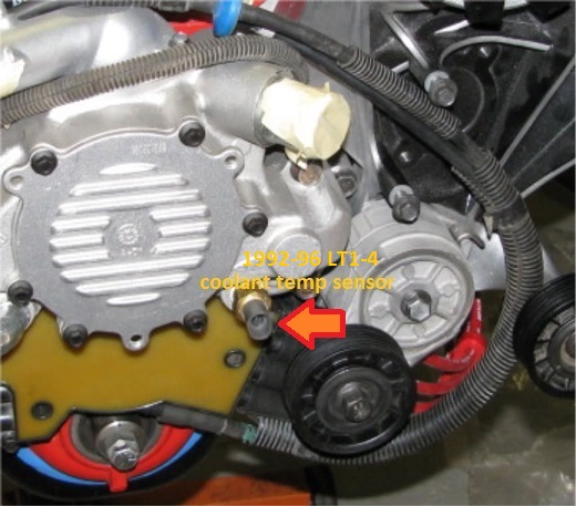
the coolant temp sensor is located on the Pass side head between # 6 and 8 plugs.
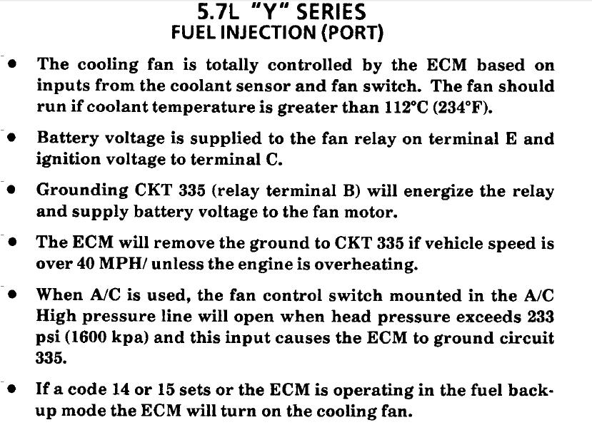
Fan control varies by year.
As I recall.
'84 has temp switch for fan only ,no ECM control;
'85 has ECM control but temp switch acts as over ride backup direct to fan
'86- '89 as stated above
'90 onward ; both fans on ECM ; no temp switch.
And all have provision to turn the fans on with A/c on.
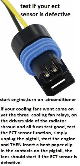
1996 and up corvettes are OBD2, which cannot use the paper clip trick.
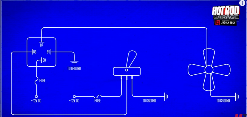
Pro tip before starting - Label your relays Relay 1, Relay 2, and Relay 3 according to the wiring diagram (your first post) and what your physical relays represent. Even if its just a sticky note. Get it all straight and stick to the same annotation while you troubleshoot.
You'll need a multimeter than can measure DC voltage and continuity:
Remove all three relays so you're only dealing with the sockets
DC Voltage tests:
1. Confirm 12V between the socket for pin 85 and the negative battery terminal on all 3 relay sockets
2. Confirm 12v between the socket for pin 30 and the negative battery terminal on relay sockets 1 and 2
Continuity tests:
1. Confirm continuity with the end of the dark green wire and the socket for pin 86 for relay 1
2. Confirm continuity with the end of the dark blue wire and the socket for pin 86 for relay 2 AND relay 3.
3. Confirm continuity between the socket for pin 87 for relay 1 and side B of the left cooling fan connector
4. Confirm continuity between side A of the left cooling fan connector and side B of the right cooling fanconnector AND the socket for pin 87 for relay #2.
5. Confirm continuity between the socket for pin 87 for relay #3 and Negative Battery Terminal
6. Confirm continuity between side A of the right cooling connector and Negative Battery Terminal.
Do the steps in order and use the negative battery terminal for your connection when I specify to. Verifying at the negative battery terminal will ensure you're circuit is making a good connection to the chassis ground. If it doesn't make it all the way back to the battery, it's a crap ground and testing it my way will reveal the problem
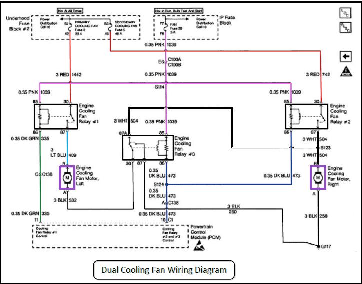
THE DIAGRAM ABOVE HAS THE CORRECT WIRE COLORS
Measured Value
Engine Coolant Temperature Sensor. 185 Ohms @ 210F, 3400 Ohms @ 68F, 7,500 Ohms @ 39 F.
Engine Oil Temperature Sensor. 185 Ohms @ 210 F, 3400 Ohms @ 68 F, 7,500 Ohms @39 F.
Oil Pressure Sender/Switch. 1 Ohms @ 0 PSI, 43 Ohms @ 30 PSI, 86 Ohms @ 60 PSI.
Fuel Quantity Sender. 0 Ohms @ Empty, 45 Ohms @ 1/2 Full, 90 Ohms @ Full.
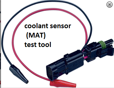
MAT (Manifold Absolute Temperature Sensor). 185 Ohms @ 210 F, 3400 Ohms @ 70 F, 15,000 Ohms @ 40 F.
Outside Temperature Sensor. 4400 Ohms @ 60 F, 2200 Ohms @ 85 F.
In Car Temp Temperature Sensor. 4400 Ohms @ 60 F, 2200 Ohms @ 85 F.
MAF (Mass Air Flow) Sensor. .4 Volts @ idle, 5 Volts @ Full Throttle.
Oxygen (O2) Sensor. .1 Volt Lean Mixture, .9 Volt Rich Mixture.
TPS (Throttle Position Sensor). .54 Volts Idle, ~ 5 Volts Full Throttle.
Sensor Locations
Sensor
Location
Engine Coolant Temperature Sensor. Front of engine, below Throttle Body.
Engine Oil Temperature Sensor. Left rear of engine, just above the oil filter.
Oil Pressure Sender/Switch. Top, left hand rear of engine.
Fuel Quantity Sender. Top of fuel tank, beneath filler pipe escutcheon panel.
MAT (Manifold Absolute Temperature Sensor). Underside of manifold air plenum at rear.
Outside Temperature Sensor. Right side of engine, top right corner of radiator.
In Car Temp Temperature Sensor. Coupe: above left seat near interior courtesy light, Convertible: center of cargo compartment lid.
MAF (Mass Air Flow) Sensor. Front of engine ahead of throttle body.
Oxygen (O2) Sensor. Left side of engine, in exhaust pipe.
TPS (Throttle Position Sensor). Right side of throttle body at the front.
this is the most consistently accurate I.R temp gun I've used for testing[/img]
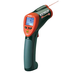
http://www.testequipmentdepot.com/extech/thermometers-and-humidity-meters/infrared-thermometers/high-temperature-infrared-thermometer-58to1832f-50to1-laser-pointer-42545.htm?utm_source=bing&utm_medium=cpc&utm_campaign=NEXT - Bing Shopping - Extech&utm_term=1100200223789&utm_content=All Extech Products
READ THE LINKED INFO
http://garage.grumpysperformance.co...ette-fan-motor-quit-working.10559/#post-84177
http://garage.grumpysperformance.com/index.php?threads/1995-corvette-fan-motor-quit-working.10559/
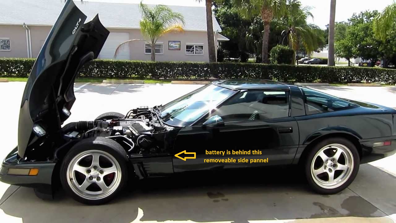
REPLACING A C4 CORVETTE BATTERY VIDEO
http://www.youtube.com/watch?feature=pl ... 03-roWP2A#!
http://www.ebay.com/itm/1995-1996-C...diator-Hose-Set-LT1-LT4-engines-/121925824251
http://garage.grumpysperformance.co...rical-glitches-in-newer-cars.5492/#post-43932
https://corvetteparts.com/item/heat...o-lower-heater-core-lt1-lt4-engines-1993-1996
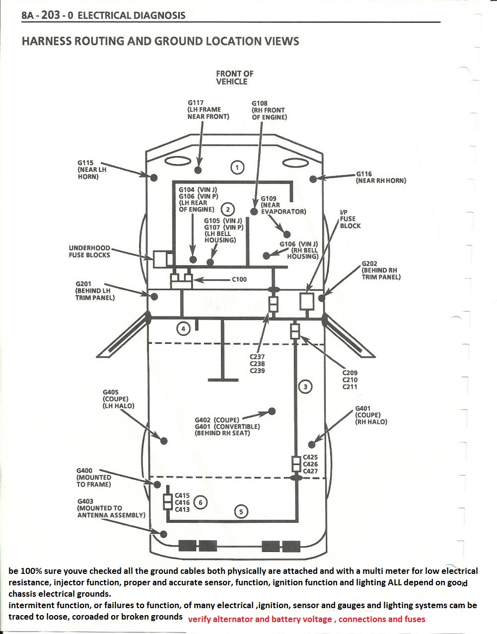
obviously the first step is labeling the cooling fan relays and getting out the shop manual looking over the testing info, and using the multi meter and checking fuses , grounds and reading up on the function, of each component, the charts above should help
http://members.shaw.ca/corvette86/Cooli ... ontrol.pdf
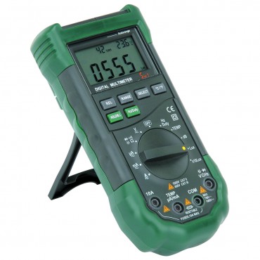
http://www.harborfreight.com/5-in-1-dig ... 98674.html
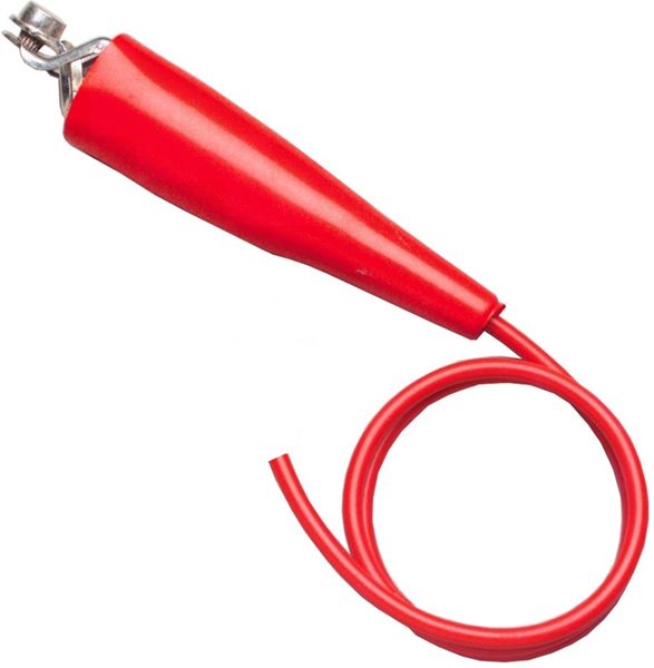
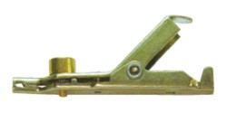
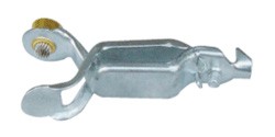
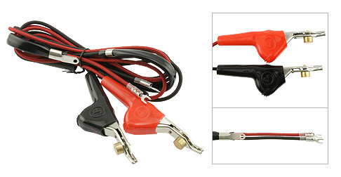
having a wide assortment of different multi meter test leads available is a huge benefit while testing
the clip test leads that test thru a wires insulation without much damage are a big help
RELATED REFERENCE THREADS
viewtopic.php?f=32&t=2697&p=18904&hilit=trouble+codes#p18904
viewtopic.php?f=80&t=728&p=18757&hilit=+sensor+locations#p18757
viewtopic.php?f=32&t=3954
viewtopic.php?f=57&t=149&hilit=sensor+locations
viewtopic.php?f=57&t=2538&p=21497&hilit=fans#p21497
viewtopic.php?f=36&t=3222&p=8575&hilit=testing+alternator#p8575
viewtopic.php?f=70&t=355&p=13196&hilit=+alternator#p13196
and finding it is making me a bit nuts, the only trouble code that came up indicated the cooling fan relay was defective,
I changed all three cooling fan, relays, checked the fuses and fuse-able links,
but this failed to clear the problem, so Im obviously over looking something here gentlemen?
this will obviously be something I should have spotted easily but at this moment Im overlooking it!
Ive pulled codes several times and it shows no further codes.
DTC P1641 FC Relay 1 Control Circuit description is located in book #2 Page 6-599 of the service manual. For the cooling fan schematic, refer to Fan Control Circuits
Ive changed the engine temp sensor on the front and on the pass side head
and the trouble code is now gone but the
radiator fans still won,t turn on yet both fans test perfectly fine, and work if I just apply battery
all fuses test good
There are three cooling fan relays...And three fuses...Lets begin with the fuses...Fuse #2 (30A)= primary cooling fan...Fuse # 5 (40A)=secondary cooling fan...Both of these are under-hood. Fuse #29 (5A)=fan fuse...Feeds power to all three relays and is located inside...If all three fuses are good; Lets check the relays..All 3 relays receive power on a Pink wire multiple from fuse#29...Ground is fired to pull relay #2 and #3 on a Dark Blue wire from the PCM C1 pin# 10...Relay #1 receives ground from PCM C1 pin#10 on the Dark Green wire...
https://www.ecklers.com/corvette/co...MIjKCGpePe3gIVgYzICh035w4jEAQYBCABEgK7ifD_BwE
https://www.rockauto.com/en/catalog...oling+system,temperature+sender+/+sensor,4748
https://www.autozone.com/repairguid...DIAGRAMS/WIRING-DIAGRAMS/_/P-0900c1528008fd94
the coolant temp sensor is located on the Pass side head between # 6 and 8 plugs.
Fan control varies by year.
As I recall.
'84 has temp switch for fan only ,no ECM control;
'85 has ECM control but temp switch acts as over ride backup direct to fan
'86- '89 as stated above
'90 onward ; both fans on ECM ; no temp switch.
And all have provision to turn the fans on with A/c on.
Pro tip before starting - Label your relays Relay 1, Relay 2, and Relay 3 according to the wiring diagram (your first post) and what your physical relays represent. Even if its just a sticky note. Get it all straight and stick to the same annotation while you troubleshoot.
You'll need a multimeter than can measure DC voltage and continuity:
Remove all three relays so you're only dealing with the sockets
DC Voltage tests:
1. Confirm 12V between the socket for pin 85 and the negative battery terminal on all 3 relay sockets
2. Confirm 12v between the socket for pin 30 and the negative battery terminal on relay sockets 1 and 2
Continuity tests:
1. Confirm continuity with the end of the dark green wire and the socket for pin 86 for relay 1
2. Confirm continuity with the end of the dark blue wire and the socket for pin 86 for relay 2 AND relay 3.
3. Confirm continuity between the socket for pin 87 for relay 1 and side B of the left cooling fan connector
4. Confirm continuity between side A of the left cooling fan connector and side B of the right cooling fanconnector AND the socket for pin 87 for relay #2.
5. Confirm continuity between the socket for pin 87 for relay #3 and Negative Battery Terminal
6. Confirm continuity between side A of the right cooling connector and Negative Battery Terminal.
Do the steps in order and use the negative battery terminal for your connection when I specify to. Verifying at the negative battery terminal will ensure you're circuit is making a good connection to the chassis ground. If it doesn't make it all the way back to the battery, it's a crap ground and testing it my way will reveal the problem
THE DIAGRAM ABOVE HAS THE CORRECT WIRE COLORS
Measured Value
Engine Coolant Temperature Sensor. 185 Ohms @ 210F, 3400 Ohms @ 68F, 7,500 Ohms @ 39 F.
Engine Oil Temperature Sensor. 185 Ohms @ 210 F, 3400 Ohms @ 68 F, 7,500 Ohms @39 F.
Oil Pressure Sender/Switch. 1 Ohms @ 0 PSI, 43 Ohms @ 30 PSI, 86 Ohms @ 60 PSI.
Fuel Quantity Sender. 0 Ohms @ Empty, 45 Ohms @ 1/2 Full, 90 Ohms @ Full.
MAT (Manifold Absolute Temperature Sensor). 185 Ohms @ 210 F, 3400 Ohms @ 70 F, 15,000 Ohms @ 40 F.
Outside Temperature Sensor. 4400 Ohms @ 60 F, 2200 Ohms @ 85 F.
In Car Temp Temperature Sensor. 4400 Ohms @ 60 F, 2200 Ohms @ 85 F.
MAF (Mass Air Flow) Sensor. .4 Volts @ idle, 5 Volts @ Full Throttle.
Oxygen (O2) Sensor. .1 Volt Lean Mixture, .9 Volt Rich Mixture.
TPS (Throttle Position Sensor). .54 Volts Idle, ~ 5 Volts Full Throttle.
Sensor Locations
Sensor
Location
Engine Coolant Temperature Sensor. Front of engine, below Throttle Body.
Engine Oil Temperature Sensor. Left rear of engine, just above the oil filter.
Oil Pressure Sender/Switch. Top, left hand rear of engine.
Fuel Quantity Sender. Top of fuel tank, beneath filler pipe escutcheon panel.
MAT (Manifold Absolute Temperature Sensor). Underside of manifold air plenum at rear.
Outside Temperature Sensor. Right side of engine, top right corner of radiator.
In Car Temp Temperature Sensor. Coupe: above left seat near interior courtesy light, Convertible: center of cargo compartment lid.
MAF (Mass Air Flow) Sensor. Front of engine ahead of throttle body.
Oxygen (O2) Sensor. Left side of engine, in exhaust pipe.
TPS (Throttle Position Sensor). Right side of throttle body at the front.
this is the most consistently accurate I.R temp gun I've used for testing[/img]
http://www.testequipmentdepot.com/extech/thermometers-and-humidity-meters/infrared-thermometers/high-temperature-infrared-thermometer-58to1832f-50to1-laser-pointer-42545.htm?utm_source=bing&utm_medium=cpc&utm_campaign=NEXT - Bing Shopping - Extech&utm_term=1100200223789&utm_content=All Extech Products
Manually spin the fan blade of the fan that doesn't work to
verify the fan motor isn't seized.
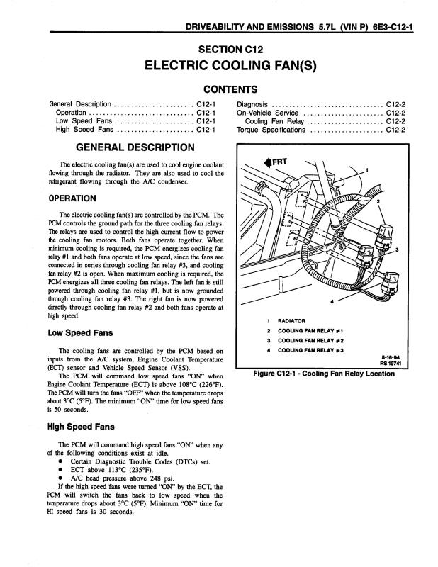
The fans use 3 relays mounted on the driver side
on the end of the radiator.
Primary cooling fan is an the driver side.
Secondary cooling fan is on the passenger side.
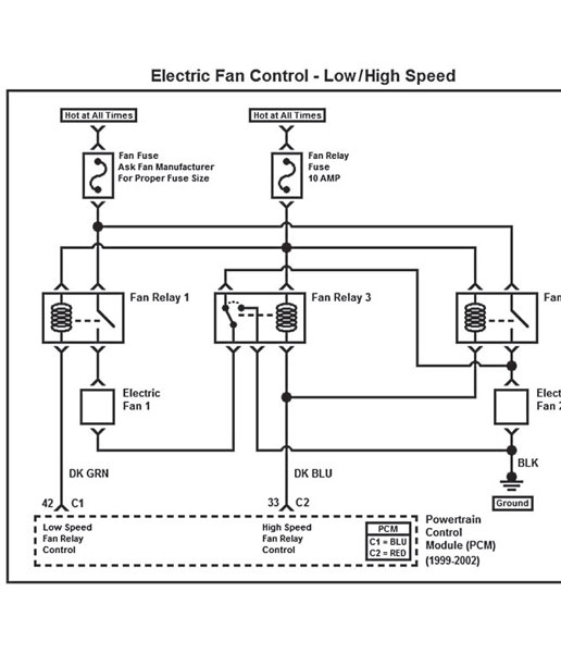
There are two modes of fan operation.
Both fans at half speed. 6 volts
Both fans at high speed. 12 volts.
There are two control lines the PCM grounds to
enable the fans.
PCM grounds the Dark Green wire for low speed.
Relay #1 is energized.
PCM grounds both the Dark Green wire and a Dark Blue
wire for high speed.
All three relays #1, #2 and #3 are energized.
Three fuses protect the circuits.
Fan fuse 5 amp located on passenger side of the dash.
This must be good because you say one fan does run.
Primary coolant fan 30 amp Maxifuse located under the hood.
Must be good if the driver side fan works.
Secondary coolant fan 40 amp Maxifuse located under the hood.
You can identify the relays by the color of the wires that
go to the relay sockets.
Relay #1 has the following colored wires.
Pink, Dark Green, Red and a Light blue wire.
Relay #2
Pink, Dark Blue, White and 2 Black wires.
Relay #3
Pink, Dark Blue, Red and a White wire.
To test the fans turn the ignition On.
Manually ground the control lines. Stick a nail
or probe, jumper wire etc... into the bottom of
the relay socket and ground the Dark Green wire.
Both fans should run at low speed.
Ground the Dark Green wire and the Dark Blue
wire and both fans should run at high speed.
Another method you can use is to carefully pry/remove
the plastic cover off of the relays. You can then
manually energize the relays by pushing down
on the metal plate.
Push down on the plate on #1 relay and both fans
should run at slow speed.
Push down the metal plate on all relays and both
fans should run at high speed.

READ THE LINKED INFO
http://garage.grumpysperformance.co...ette-fan-motor-quit-working.10559/#post-84177
http://garage.grumpysperformance.com/index.php?threads/1995-corvette-fan-motor-quit-working.10559/
REPLACING A C4 CORVETTE BATTERY VIDEO
http://www.youtube.com/watch?feature=pl ... 03-roWP2A#!
http://www.ebay.com/itm/1995-1996-C...diator-Hose-Set-LT1-LT4-engines-/121925824251
http://garage.grumpysperformance.co...rical-glitches-in-newer-cars.5492/#post-43932
https://corvetteparts.com/item/heat...o-lower-heater-core-lt1-lt4-engines-1993-1996
obviously the first step is labeling the cooling fan relays and getting out the shop manual looking over the testing info, and using the multi meter and checking fuses , grounds and reading up on the function, of each component, the charts above should help
http://members.shaw.ca/corvette86/Cooli ... ontrol.pdf
http://www.harborfreight.com/5-in-1-dig ... 98674.html
having a wide assortment of different multi meter test leads available is a huge benefit while testing
the clip test leads that test thru a wires insulation without much damage are a big help
RELATED REFERENCE THREADS
viewtopic.php?f=32&t=2697&p=18904&hilit=trouble+codes#p18904
viewtopic.php?f=80&t=728&p=18757&hilit=+sensor+locations#p18757
viewtopic.php?f=32&t=3954
viewtopic.php?f=57&t=149&hilit=sensor+locations
viewtopic.php?f=57&t=2538&p=21497&hilit=fans#p21497
viewtopic.php?f=36&t=3222&p=8575&hilit=testing+alternator#p8575
viewtopic.php?f=70&t=355&p=13196&hilit=+alternator#p13196
Last edited by a moderator: