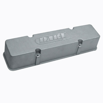
as many guys find out theres a bunch of valve covers on the market with no provisions to mount a breather, or add oil to the engine,
in many cases theres KNOCK OUTS or places designed to punch out
for a breather or a oil cap, on many there is no provision so what do you do?
obviously you need to inspect and measure carefully because you sure don,t want to locate a breather tube where it interferes with the rockers etc.
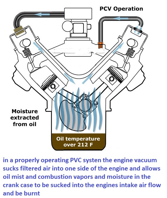
a properly functioning PVC valve on one valve cover and a breather on the other side will promote the removal of moisture PROVIDED the engine oil reaches and maintains a MINIMUM oil temp in the oil pan of 215F for at least a few minutes, to boil off that trapped moisture
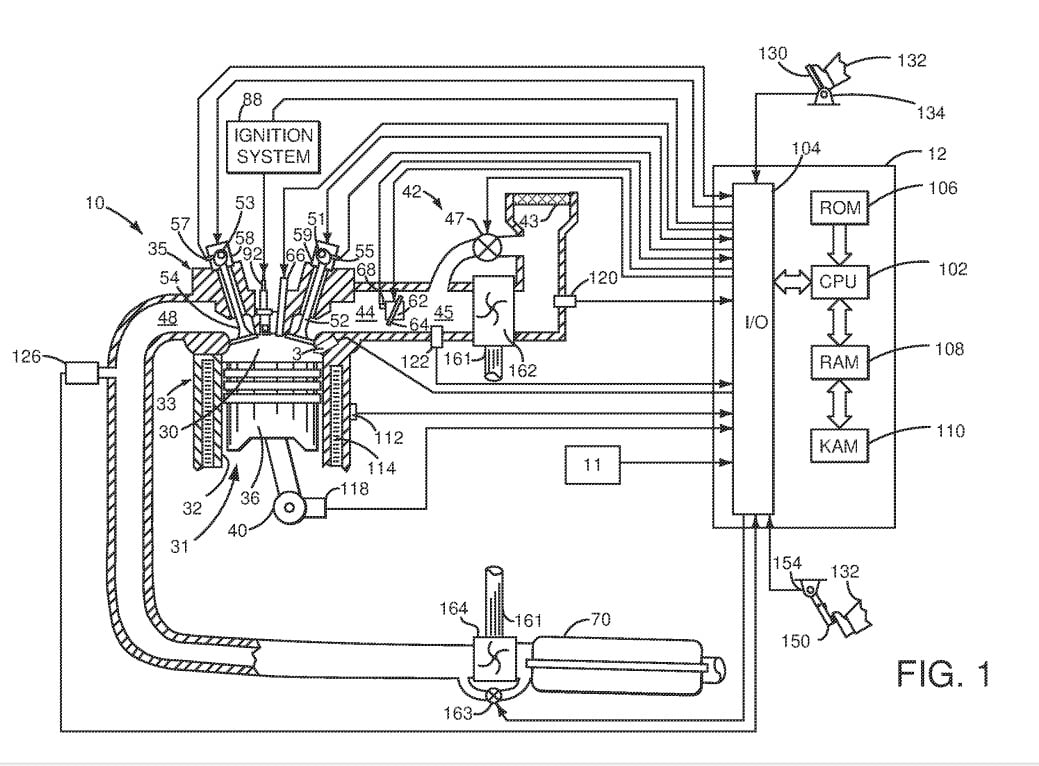
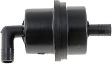
The PCV valve system vents crankcase gases into the engine air intake where they are burned with the fuel and air mixture. The PCV valve system keeps pollutants from being released into the atmosphere, and also helps to keep the engine oil clean, by ridding the crankcase of moisture and corrosive fumes. The PCV valve system consists of the PCV valve, it's mounting grommet, the nipple in the air intake and the connecting hoses. On some engine applications, the PCV valve system is connected with the evaporative emission system.
if you only have the vacuum connection at the carb base and you need to install both the brake booster vacuum line and a PVC vacuum line a barbed tee fitting could be used ,
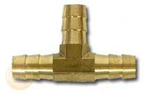
but its not ideal simply because the PVC vacuum line will constantly be flowing oil/fuel vapor that may degrade the brake booster over time if they share the same vacuum source.
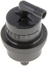
adding a contaminant filter to the BRAKE booster vacuum line reduces that potential issue
Dorman 80195 Power Brake Filter
http://www.atlanticz.ca/zclub/techtips/enginepressure/pcv.htm
http://garage.grumpysperformance.com/index.php?threads/pcv-system-routing.10999/#post-48572
http://www.autopartswarehouse.com/brake_booster_filter~pop.html
positive - crankcase - ventilation = Pcv valve

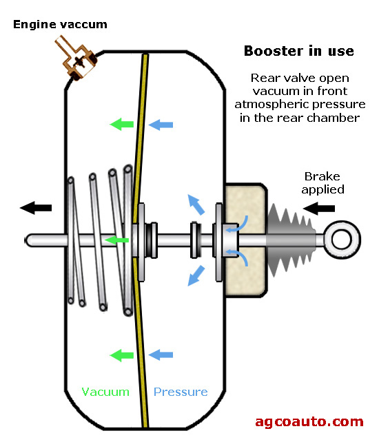
keep in mind the brake vacuum to the brake booster is generally connected to the intake manifolds plenum vacuum, if you don,t have a proper PVC valve on the valve cover on at least one valve cover and a breather on the other valve cover you may have engine crank case back pressure reduce the intake plenum vacuum, reaching the brake booster reduced
http://auto.howstuffworks.com/positive-crankcase-ventilation-system.htm
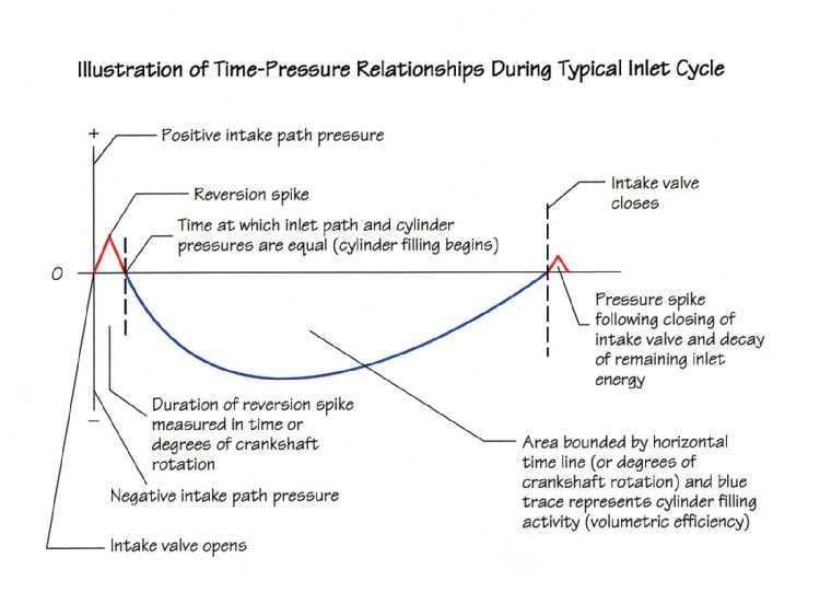
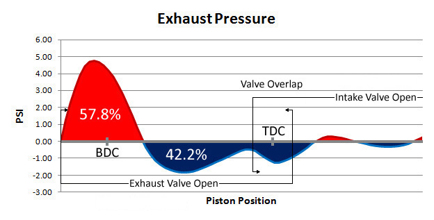
almost any cam will cause intake manifold reversion or pulsed low speed air flow in the engines intake runners , this often results in the PCV valve rapidly oscillating in response to the changes in air vacuum/pressure
https://www.summitracing.com/parts/...2077271757085&utm_content=GSAPI+5ba29e8f8c24c

AS ALWAYS THERES A GREAT DEAL OF INFO IN THE LINKS
viewtopic.php?f=32&t=6011&p=18597#p18597
viewtopic.php?f=80&t=1288&hilit=pvc+valve
viewtopic.php?f=87&t=4636&p=12451#p12451
viewtopic.php?f=44&t=4912
http://garage.grumpysperformance.com/index.php?threads/oil-stained-intake-runners.14209/
viewtopic.php?f=32&t=6011&p=18597#p18597
http://auto.howstuffworks.com/positive-crankcase-ventilation-system.htm
http://garage.grumpysperformance.com/index.php?threads/blow-bye-and-breathers.10646/
http://en.wikipedia.org/wiki/PCV_valve
http://www.secondchancegarage.com/public/239.cfm
http://www.2carpros.com/how_does_it_work/pcv_valve.htm
http://www.aa1car.com/library/pcv.htm
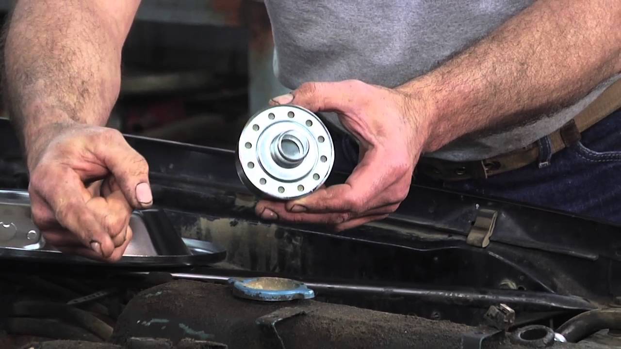
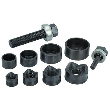
youll want one of these tools to cut a clean round hole
Includes punches and dies for 1/2", 3/4", 1" and 1-1/4" pipe and conduit, in a blow mold case
http://www.harborfreight.com/knockout-p ... 91201.html

you drill a small hole, put the threaded rod thru, attach the punch bit and receiver cup and slowly tighten the tool, and it cuts out the correct size hole without distorting the valve cover
MOST VALVE COVERS COME WITH AT LEAST ONE HOLE TO ADD OIL OR MOUNT A PVC CONNECTION.
BUT NOT ALL
http://www.jegs.com/p/JEGS/JEGS-Billet- ... 0/10002/-1
http://www.jegs.com/p/JEGS/JEGS-Billet- ... 1/10002/-1
http://www.jegs.com/p/Billet-Specialtie ... 0/10002/-1
http://www.jegs.com/p/Mr-Gasket/Mr-Gask ... 9/10002/-1
http://www.filtercouncil.org/techdata/tsbs/94-2R1.pdf
http://www.aa1car.com/library/pcv.htm
be aware that condensation, trapped in the engine , can cause the oil to look like lard or rancid butter, if your PVC valve won.t clear the moisture this can be a problem with engines that don,t get run frequently as moisture plus exhaust gases can form acids
http://garage.grumpysperformance.com/index.php?threads/tracking-down-an-oil-leak.1430/#post-3168
since the pvc has almost no real effect on the engines basic function,
(remember the Chevy small block engines had road draft tubes long before they had PVCs)
and the pvc is simply used to significantly reduce emissions and slightly lower the crank case pressure due to high pressure gases seeping past the rings,
the obvious test is to remove and plug one or both hoses connected to the intake or throttle body and see what if anything changes.
(and it most likely will change because your basically now running a self installed vacuum leak)
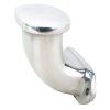
btw you CAN,T RUN AN OPEN LINE TO THE VALVE COVER WITH A 90 DEGREE OPEN ADAPTER YOU NEED A TRUE PVC, that closes at idle
READ
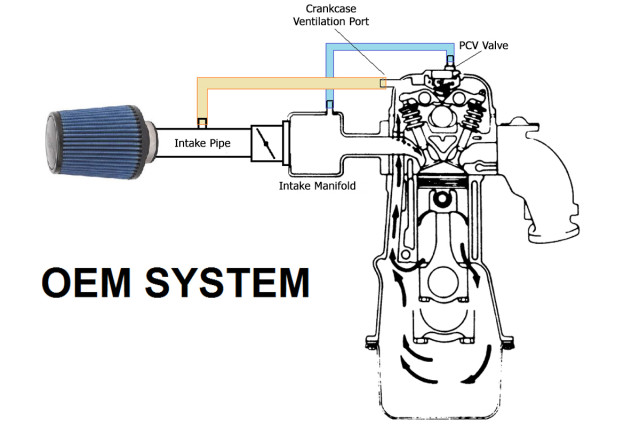
Positive Crankcase Ventilation is a system that was developed to remove harmful vapors from the engine and to prevent those vapors from being expelled into the atmosphere. The PCV system does this by using manifold vacuum to draw vapors from the crankcase into the intake manifold. Vapor is then carried with the fuel/air mixture into the combustion chambers where it is burned. The flow or circulation within the system is controlled by the PCV Valve. The PCV Valve is effective as both a crankcase ventilation system and as a pollution control device.
PCV systems have been standard equipment on all new cars since the early sixties. Prior to 1963 PCV was only used in California. There are a variety of PCV systems used on various makes and models of cars produced since 1963, but all function essentially the same.
PCV systems can be described as either open or closed. The two systems are quite similar. However, the closed system in use since 1968 is more effective at air pollution control. The systems differ in the manner in which fresh air enters the crankcase and excessive vapor is expelled.
Open PCV Systems
The open system draws fresh air though a vented oil filler cap. This presents no problem as long as the vapor volume is minimal. However, when the crankcase vapor becomes excessive it is forced back through the vented oil filler cap and into the open atmosphere. The open PCV system, though successful at removing contaminated vapors from the crankcase, is not completely effective as a pollution control device.
Closed PCV Systems
The closed PCV system draws fresh air from the air filter housing. The oil filler cap in this system is NOT vented. Consequently, excess vapor will be carried back to the air filter housing and from there into the intake manifold. The closed system prevents vapor, whether normal or excessive, from reaching the open atmosphere. The closed system is very effective as an air pollution control device.
The PCV Valve
The most critical part in the PCV system is the flow control valve, commonly referred to as the PCV valve. The purpose of the PCV valve is to meter the flow of the vapor from the crankcase to the intake manifold. This is necessary in order to provide proper ventilation for the crankcase, while not upsetting the fuel/air mixture for combustion.
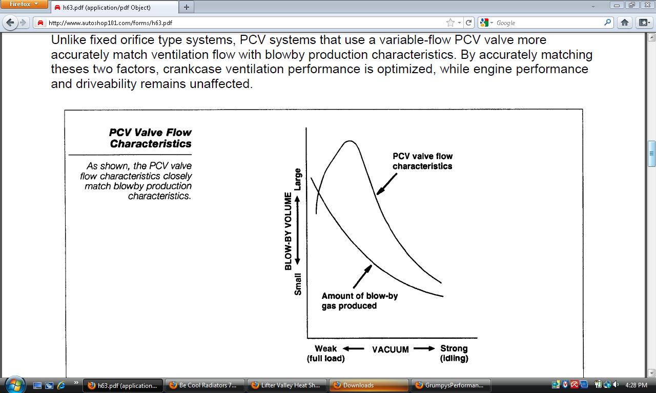
Blow-by gases and vapor should be removed at about the same rate they enter the crankcase. Since blow-by is minimal at idle and increases during high speed operation, the PCV valve must control the flow of vapor accordingly. The PCV valve is designed to compensate for the engine ventilation needs at varying engine speeds. It is operated by manifold vacuum which increases or decreases as engine speeds change.
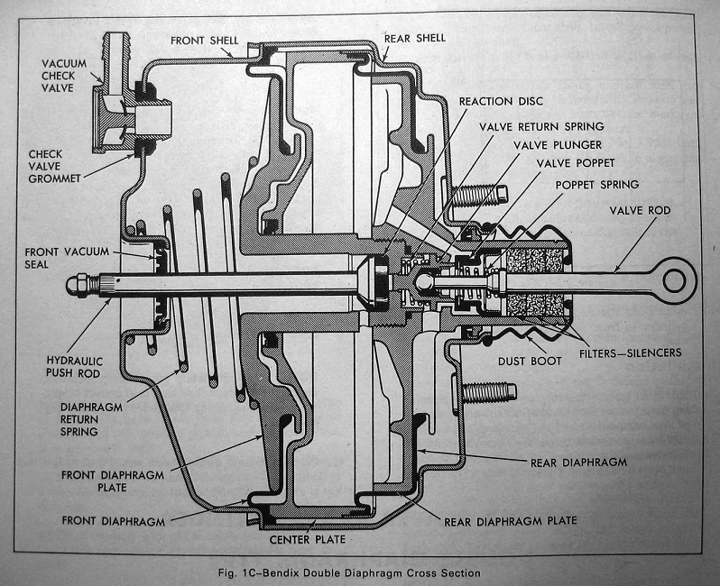
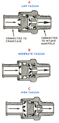
For example, at low or idle engine speeds manifold vacuum is high. This pulls the plunger to the extreme forward position, or manifold end of the valve. Due to the shape of the plunger, vapor flow is reduced to a minimum. The low rate of the flow is adequate for ventilation purposes and will not upset the fuel/air mixture ratio.
At high speeds manifold vacuum is decreased. The plunger is only drawn to a point about midway in the housing. This allows a maximum flow of vapor. Since the engine needs more fuel/air mixture at high speeds, the introduction of more vapor does not affect performance. In the event of a backfire, pressure from the intake manifold forces the plunger to the closed or engine-off position. This prevents the backfire flame from reaching the crankcase and exploding the combustible vapor.
A neglected PCV system will soon fail to function and the result can be expensive as well as troublesome for the car owner. If the crankcase is not adequately ventilated, the motor oil will quickly become contaminated and heavy sludge accumulations will begin to form. Internal parts, not protected by the motor oil, will begin to rust and/or corrode due to the water and acids that will become trapped within the crankcase. If the PCV system is not functioning properly, the flow of crankcase vapor into the intake manifold will not be properly metered. This, in turn, will upset the fuel/air mixture for combustion and cause rough idling or even stalling of the engine. Furthermore, intake and exhaust valves, in addition to spark plugs, may well be burned and rendered useless, prematurely affecting performance and requiring expensive repairs. To assure trouble-free performance of the PCV system and, in turn, the engine and vehicle, routine maintenance of the PCV system is absolutely recommended and required.
A PCV valve should never be cleaned and placed back into service. Cleaning a PCV valve will result in a clean PCV valve; not a new PCV valve. There are contaminants that will remain in the PCV valve that can never be flushed out. Additionally, there is an amount of wear that will be experienced by the spring that cleaning cannot replace. The recommended replacement intervals are a maximum of 12 months or 10,000 miles (16,000 km). Since vehicles and operating conditions vary, the valve may have to be serviced more frequently. If it is suspected that the valve is sticking or if there is evidence of sludge, the valve should be replaced.
All hoses or tubes used in the PCV system should be cleaned and inspected. If any cracks or breaks are noticed in the hose, it should also be replaced. All hose connections should be inspected to assure an air-tight seal.
Proper servicing of the PCV valve system will help reduce overall vehicle emissions.
http://en.wikipedia.org/wiki/PCV_valve
http://en.wikipedia.org/wiki/PCV_valve
http://www.tegger.com/hondafaq/pcv-replace/
http://www.autoshop101.com/forms/h63.pdf
http://www.aa1car.com/library/pcv.htm
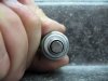
step one
make sure the pcv valve is functioning correctly
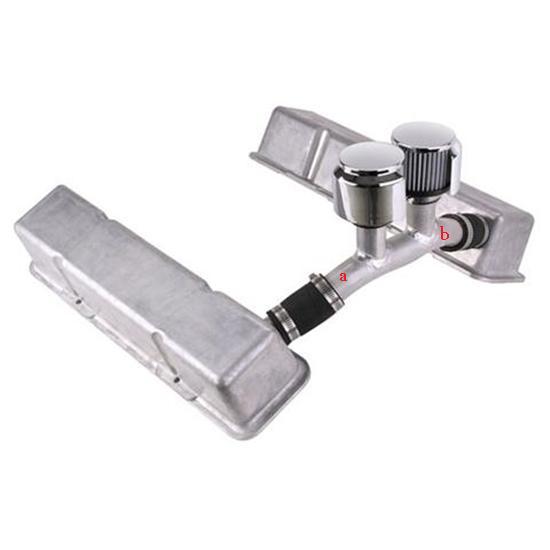

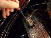
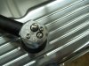
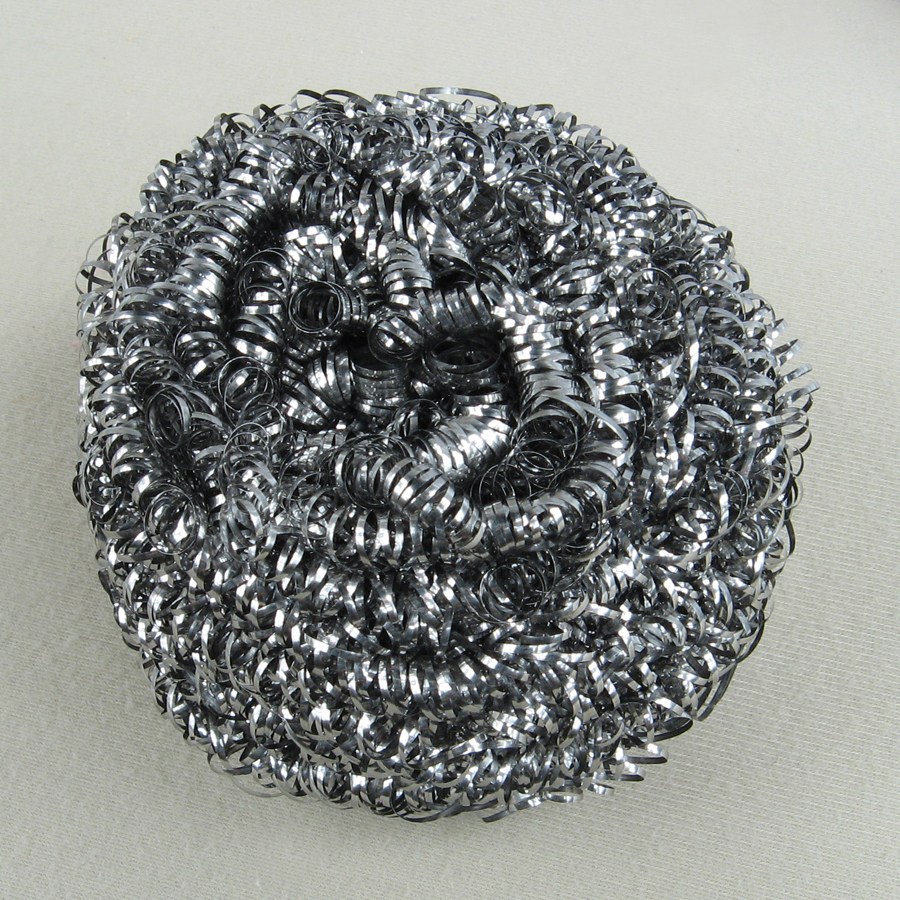
BTW we found we could just insert one or two stainless steel scrub pads in the breather tube space, (A and B) as that will absolutely control any air flow turbulence, that tends to drag oil out the breathers and make the engine a oil soak mess.
I know we did that on road race cars, for oil control on crank case breathers, and it drastically improved the flow back rates and controlled the formation of oil foam, allowing the oil to flow back with a noticeable reduction in air trapped in the oil.
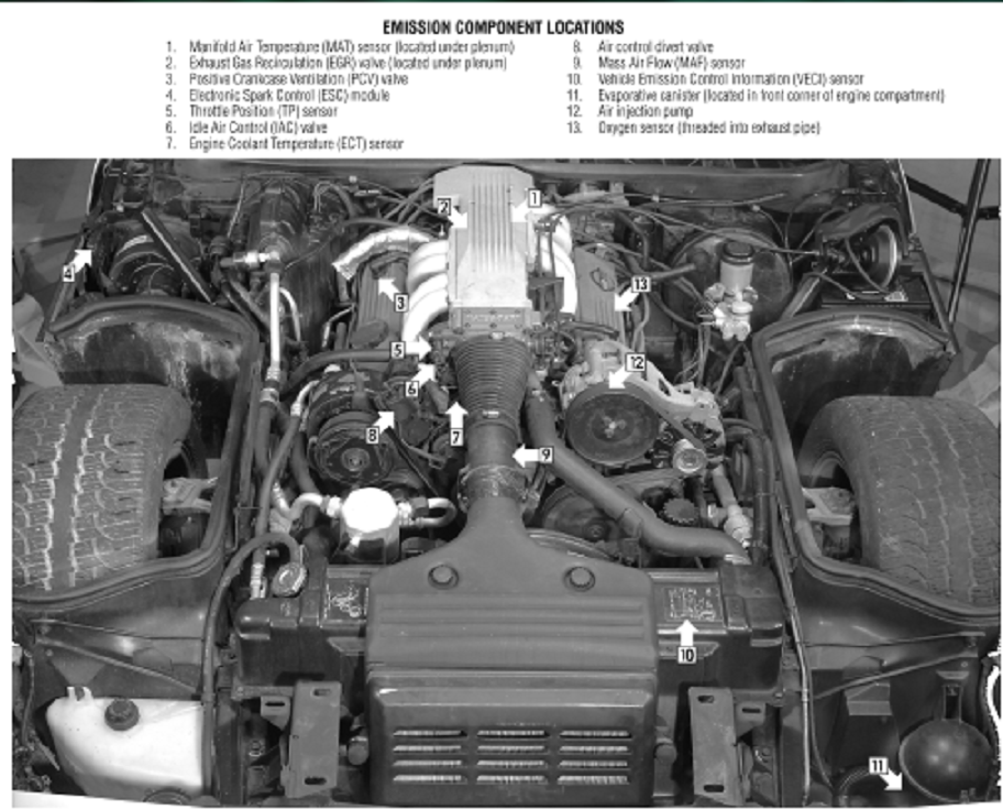
EMISSION COMPONENT LOCATIONS
http://www.speedwaymotors.com/Speedway- ... ,1887.html
once more a rather simple weekend project with a decent welder, if youve got minimal skill and the calculator below to use to fabricate your own custom version, maybe even get it powder coated
http://www.metalgeek.com/static/cope.pcgi
custom welded aluminum valve cover breathers are an option,
read thru this related thread
viewtopic.php?f=52&t=2005&p=5328&hilit=positive+crankcase#p5328
http://www.harborfreight.com/knockout-p ... 91201.html
in some covers you will need to punch a hole and add a grommet
http://garage.grumpysperformance.co...breather-hole-in-valve-covers.2005/#post-5328
http://garage.grumpysperformance.com/index.php?threads/need-help-with-evac-system.15939/#post-95997
http://garage.grumpysperformance.com/index.php?threads/catch-can-related-info.4636/#post-12451
http://garage.grumpysperformance.com/index.php?threads/pcv-system-routing.10999/#post-48572
https://auto.howstuffworks.com/positive-crankcase-ventilation-system.htm
almost any cam will cause intake manifold reversion or pulsed low speed air flow in the engines intake runners , yes its common, this often results in the PCV valve rapidly oscillating in response to the changes in air vacuum/pressure
http://garage.grumpysperformance.co...breather-hole-in-valve-covers.2005/#post-5328
http://garage.grumpysperformance.com/index.php?threads/intake-runner-reversion.4131/
http://garage.grumpysperformance.com/index.php?threads/oily-crud-on-intake-valves.12083/#post-57903
[1] synthetic oil desolves that yellow 3m weatherstrip gasket adhesive than many guys use over a few months time so you cant use it to glue valve cover gaskets
[2]you must use a o2 safe gasket cement like the BLACK RTV silicone cement and you must clean and degrease the cover with acetone or a similar solvent before glueing on the gasket to get the best retention
[3]you need to allow at least a few hours to over night, depends mostly on temp. for that black silicone gasket cement to set up before installing the valve covers, and placing them gasket side down on a table with a sheet of wax paper under them and a 20lb weight on top of each valve cover while the cement sets up is the best way to insure the gaskets stay correctly aligned on the valve covers perimeter
[4]a light coat of (PAM) cooking spray on the lower gasket surface keeps them from sticking to the cylinder heads after installation
[5] these gasket retaining rings add a great deal to the valve covers ability to firmly hold the gasket WITHOUT bending SHEET METAL VALVE COVERS OR CRACKING CAST ALUMINUM VALVE COVERS AND ARE WELL WORTH THE MINIMAL COST
[6]doing it correctly the first time saves time and money
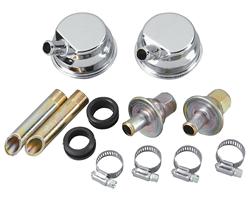
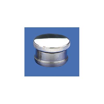
theres several sources for oil fill caps that can be welded in or use rubber grommets
http://www.pitstopusa.com/detail.aspx?ID=8726
http://www.engineprofessional.com/articles/EPQ315_34-44.pdf
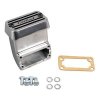
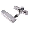
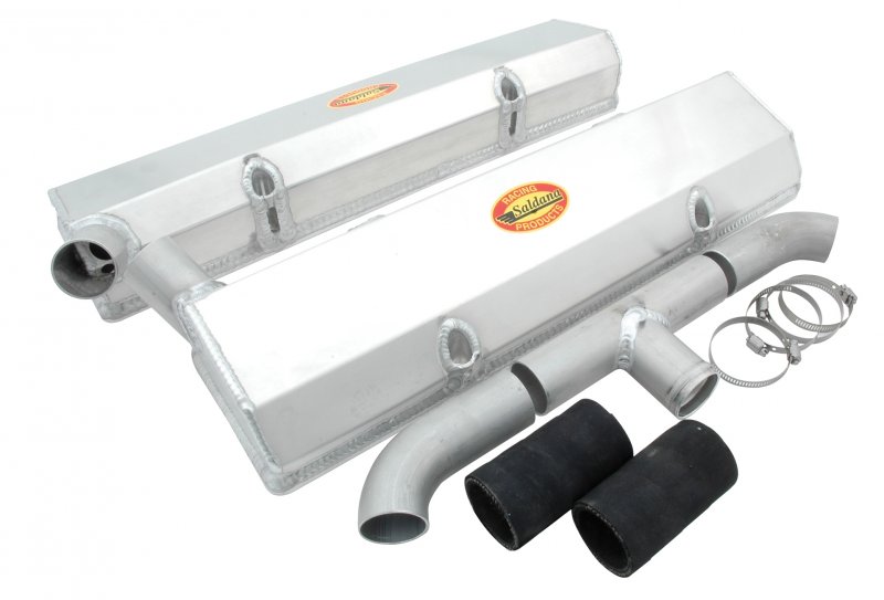
morroso sells these,kits you can weld into your valve covers, thier used too connect two valve covers at the front of the engine,and the location prevents a good deal of oil from reaching the breathers, Ive seen guys weld up their own custom version using 1" EMT conduit and have virtually nothing in cost if they have a welder and two tall sheet metal style valve covers, (a great reason to own a decent MIG or TIG)and weld in a washer inside each tube to act as a baffle, (this helps)
http://www.metalgeek.com/static/cope.pcgi
and then hook up the PVC to the vertical section and get very low oil flow into the PVC due mostly to both the distance and location on the front over the T-stat housing being far further up and forward reducing the oils tendency to flow to the PVC
in many cases theres KNOCK OUTS or places designed to punch out
for a breather or a oil cap, on many there is no provision so what do you do?
obviously you need to inspect and measure carefully because you sure don,t want to locate a breather tube where it interferes with the rockers etc.
a properly functioning PVC valve on one valve cover and a breather on the other side will promote the removal of moisture PROVIDED the engine oil reaches and maintains a MINIMUM oil temp in the oil pan of 215F for at least a few minutes, to boil off that trapped moisture
The PCV valve system vents crankcase gases into the engine air intake where they are burned with the fuel and air mixture. The PCV valve system keeps pollutants from being released into the atmosphere, and also helps to keep the engine oil clean, by ridding the crankcase of moisture and corrosive fumes. The PCV valve system consists of the PCV valve, it's mounting grommet, the nipple in the air intake and the connecting hoses. On some engine applications, the PCV valve system is connected with the evaporative emission system.
if you only have the vacuum connection at the carb base and you need to install both the brake booster vacuum line and a PVC vacuum line a barbed tee fitting could be used ,
but its not ideal simply because the PVC vacuum line will constantly be flowing oil/fuel vapor that may degrade the brake booster over time if they share the same vacuum source.
adding a contaminant filter to the BRAKE booster vacuum line reduces that potential issue
Dorman 80195 Power Brake Filter
http://www.atlanticz.ca/zclub/techtips/enginepressure/pcv.htm
http://garage.grumpysperformance.com/index.php?threads/pcv-system-routing.10999/#post-48572
http://www.autopartswarehouse.com/brake_booster_filter~pop.html
positive - crankcase - ventilation = Pcv valve
keep in mind the brake vacuum to the brake booster is generally connected to the intake manifolds plenum vacuum, if you don,t have a proper PVC valve on the valve cover on at least one valve cover and a breather on the other valve cover you may have engine crank case back pressure reduce the intake plenum vacuum, reaching the brake booster reduced
http://auto.howstuffworks.com/positive-crankcase-ventilation-system.htm
almost any cam will cause intake manifold reversion or pulsed low speed air flow in the engines intake runners , this often results in the PCV valve rapidly oscillating in response to the changes in air vacuum/pressure
https://www.summitracing.com/parts/...2077271757085&utm_content=GSAPI+5ba29e8f8c24c
AS ALWAYS THERES A GREAT DEAL OF INFO IN THE LINKS
viewtopic.php?f=32&t=6011&p=18597#p18597
viewtopic.php?f=80&t=1288&hilit=pvc+valve
viewtopic.php?f=87&t=4636&p=12451#p12451
viewtopic.php?f=44&t=4912
http://garage.grumpysperformance.com/index.php?threads/oil-stained-intake-runners.14209/
viewtopic.php?f=32&t=6011&p=18597#p18597
http://auto.howstuffworks.com/positive-crankcase-ventilation-system.htm
http://garage.grumpysperformance.com/index.php?threads/blow-bye-and-breathers.10646/
http://en.wikipedia.org/wiki/PCV_valve
http://www.secondchancegarage.com/public/239.cfm
http://www.2carpros.com/how_does_it_work/pcv_valve.htm
http://www.aa1car.com/library/pcv.htm
youll want one of these tools to cut a clean round hole
Includes punches and dies for 1/2", 3/4", 1" and 1-1/4" pipe and conduit, in a blow mold case
http://www.harborfreight.com/knockout-p ... 91201.html
you drill a small hole, put the threaded rod thru, attach the punch bit and receiver cup and slowly tighten the tool, and it cuts out the correct size hole without distorting the valve cover
MOST VALVE COVERS COME WITH AT LEAST ONE HOLE TO ADD OIL OR MOUNT A PVC CONNECTION.
BUT NOT ALL
http://www.jegs.com/p/JEGS/JEGS-Billet- ... 0/10002/-1
http://www.jegs.com/p/JEGS/JEGS-Billet- ... 1/10002/-1
http://www.jegs.com/p/Billet-Specialtie ... 0/10002/-1
http://www.jegs.com/p/Mr-Gasket/Mr-Gask ... 9/10002/-1
http://www.filtercouncil.org/techdata/tsbs/94-2R1.pdf
http://www.aa1car.com/library/pcv.htm
be aware that condensation, trapped in the engine , can cause the oil to look like lard or rancid butter, if your PVC valve won.t clear the moisture this can be a problem with engines that don,t get run frequently as moisture plus exhaust gases can form acids
http://garage.grumpysperformance.com/index.php?threads/tracking-down-an-oil-leak.1430/#post-3168
since the pvc has almost no real effect on the engines basic function,
(remember the Chevy small block engines had road draft tubes long before they had PVCs)
and the pvc is simply used to significantly reduce emissions and slightly lower the crank case pressure due to high pressure gases seeping past the rings,
the obvious test is to remove and plug one or both hoses connected to the intake or throttle body and see what if anything changes.
(and it most likely will change because your basically now running a self installed vacuum leak)
btw you CAN,T RUN AN OPEN LINE TO THE VALVE COVER WITH A 90 DEGREE OPEN ADAPTER YOU NEED A TRUE PVC, that closes at idle
READ
Positive Crankcase Ventilation is a system that was developed to remove harmful vapors from the engine and to prevent those vapors from being expelled into the atmosphere. The PCV system does this by using manifold vacuum to draw vapors from the crankcase into the intake manifold. Vapor is then carried with the fuel/air mixture into the combustion chambers where it is burned. The flow or circulation within the system is controlled by the PCV Valve. The PCV Valve is effective as both a crankcase ventilation system and as a pollution control device.
PCV systems have been standard equipment on all new cars since the early sixties. Prior to 1963 PCV was only used in California. There are a variety of PCV systems used on various makes and models of cars produced since 1963, but all function essentially the same.
PCV systems can be described as either open or closed. The two systems are quite similar. However, the closed system in use since 1968 is more effective at air pollution control. The systems differ in the manner in which fresh air enters the crankcase and excessive vapor is expelled.
Open PCV Systems
The open system draws fresh air though a vented oil filler cap. This presents no problem as long as the vapor volume is minimal. However, when the crankcase vapor becomes excessive it is forced back through the vented oil filler cap and into the open atmosphere. The open PCV system, though successful at removing contaminated vapors from the crankcase, is not completely effective as a pollution control device.
Closed PCV Systems
The closed PCV system draws fresh air from the air filter housing. The oil filler cap in this system is NOT vented. Consequently, excess vapor will be carried back to the air filter housing and from there into the intake manifold. The closed system prevents vapor, whether normal or excessive, from reaching the open atmosphere. The closed system is very effective as an air pollution control device.
The PCV Valve
The most critical part in the PCV system is the flow control valve, commonly referred to as the PCV valve. The purpose of the PCV valve is to meter the flow of the vapor from the crankcase to the intake manifold. This is necessary in order to provide proper ventilation for the crankcase, while not upsetting the fuel/air mixture for combustion.
Blow-by gases and vapor should be removed at about the same rate they enter the crankcase. Since blow-by is minimal at idle and increases during high speed operation, the PCV valve must control the flow of vapor accordingly. The PCV valve is designed to compensate for the engine ventilation needs at varying engine speeds. It is operated by manifold vacuum which increases or decreases as engine speeds change.
For example, at low or idle engine speeds manifold vacuum is high. This pulls the plunger to the extreme forward position, or manifold end of the valve. Due to the shape of the plunger, vapor flow is reduced to a minimum. The low rate of the flow is adequate for ventilation purposes and will not upset the fuel/air mixture ratio.
At high speeds manifold vacuum is decreased. The plunger is only drawn to a point about midway in the housing. This allows a maximum flow of vapor. Since the engine needs more fuel/air mixture at high speeds, the introduction of more vapor does not affect performance. In the event of a backfire, pressure from the intake manifold forces the plunger to the closed or engine-off position. This prevents the backfire flame from reaching the crankcase and exploding the combustible vapor.
A neglected PCV system will soon fail to function and the result can be expensive as well as troublesome for the car owner. If the crankcase is not adequately ventilated, the motor oil will quickly become contaminated and heavy sludge accumulations will begin to form. Internal parts, not protected by the motor oil, will begin to rust and/or corrode due to the water and acids that will become trapped within the crankcase. If the PCV system is not functioning properly, the flow of crankcase vapor into the intake manifold will not be properly metered. This, in turn, will upset the fuel/air mixture for combustion and cause rough idling or even stalling of the engine. Furthermore, intake and exhaust valves, in addition to spark plugs, may well be burned and rendered useless, prematurely affecting performance and requiring expensive repairs. To assure trouble-free performance of the PCV system and, in turn, the engine and vehicle, routine maintenance of the PCV system is absolutely recommended and required.
A PCV valve should never be cleaned and placed back into service. Cleaning a PCV valve will result in a clean PCV valve; not a new PCV valve. There are contaminants that will remain in the PCV valve that can never be flushed out. Additionally, there is an amount of wear that will be experienced by the spring that cleaning cannot replace. The recommended replacement intervals are a maximum of 12 months or 10,000 miles (16,000 km). Since vehicles and operating conditions vary, the valve may have to be serviced more frequently. If it is suspected that the valve is sticking or if there is evidence of sludge, the valve should be replaced.
All hoses or tubes used in the PCV system should be cleaned and inspected. If any cracks or breaks are noticed in the hose, it should also be replaced. All hose connections should be inspected to assure an air-tight seal.
Proper servicing of the PCV valve system will help reduce overall vehicle emissions.
http://en.wikipedia.org/wiki/PCV_valve
http://en.wikipedia.org/wiki/PCV_valve
http://www.tegger.com/hondafaq/pcv-replace/
http://www.autoshop101.com/forms/h63.pdf
http://www.aa1car.com/library/pcv.htm
step one
make sure the pcv valve is functioning correctly
BTW we found we could just insert one or two stainless steel scrub pads in the breather tube space, (A and B) as that will absolutely control any air flow turbulence, that tends to drag oil out the breathers and make the engine a oil soak mess.
I know we did that on road race cars, for oil control on crank case breathers, and it drastically improved the flow back rates and controlled the formation of oil foam, allowing the oil to flow back with a noticeable reduction in air trapped in the oil.
EMISSION COMPONENT LOCATIONS
http://www.speedwaymotors.com/Speedway- ... ,1887.html
once more a rather simple weekend project with a decent welder, if youve got minimal skill and the calculator below to use to fabricate your own custom version, maybe even get it powder coated
http://www.metalgeek.com/static/cope.pcgi
custom welded aluminum valve cover breathers are an option,
read thru this related thread
viewtopic.php?f=52&t=2005&p=5328&hilit=positive+crankcase#p5328
http://www.harborfreight.com/knockout-p ... 91201.html
in some covers you will need to punch a hole and add a grommet
http://garage.grumpysperformance.co...breather-hole-in-valve-covers.2005/#post-5328
http://garage.grumpysperformance.com/index.php?threads/need-help-with-evac-system.15939/#post-95997
http://garage.grumpysperformance.com/index.php?threads/catch-can-related-info.4636/#post-12451
http://garage.grumpysperformance.com/index.php?threads/pcv-system-routing.10999/#post-48572
https://auto.howstuffworks.com/positive-crankcase-ventilation-system.htm
almost any cam will cause intake manifold reversion or pulsed low speed air flow in the engines intake runners , yes its common, this often results in the PCV valve rapidly oscillating in response to the changes in air vacuum/pressure
http://garage.grumpysperformance.co...breather-hole-in-valve-covers.2005/#post-5328
http://garage.grumpysperformance.com/index.php?threads/intake-runner-reversion.4131/
http://garage.grumpysperformance.com/index.php?threads/oily-crud-on-intake-valves.12083/#post-57903
[1] synthetic oil desolves that yellow 3m weatherstrip gasket adhesive than many guys use over a few months time so you cant use it to glue valve cover gaskets
[2]you must use a o2 safe gasket cement like the BLACK RTV silicone cement and you must clean and degrease the cover with acetone or a similar solvent before glueing on the gasket to get the best retention
[3]you need to allow at least a few hours to over night, depends mostly on temp. for that black silicone gasket cement to set up before installing the valve covers, and placing them gasket side down on a table with a sheet of wax paper under them and a 20lb weight on top of each valve cover while the cement sets up is the best way to insure the gaskets stay correctly aligned on the valve covers perimeter
[4]a light coat of (PAM) cooking spray on the lower gasket surface keeps them from sticking to the cylinder heads after installation
[5] these gasket retaining rings add a great deal to the valve covers ability to firmly hold the gasket WITHOUT bending SHEET METAL VALVE COVERS OR CRACKING CAST ALUMINUM VALVE COVERS AND ARE WELL WORTH THE MINIMAL COST
[6]doing it correctly the first time saves time and money
theres several sources for oil fill caps that can be welded in or use rubber grommets
http://www.pitstopusa.com/detail.aspx?ID=8726
http://www.engineprofessional.com/articles/EPQ315_34-44.pdf
morroso sells these,kits you can weld into your valve covers, thier used too connect two valve covers at the front of the engine,and the location prevents a good deal of oil from reaching the breathers, Ive seen guys weld up their own custom version using 1" EMT conduit and have virtually nothing in cost if they have a welder and two tall sheet metal style valve covers, (a great reason to own a decent MIG or TIG)and weld in a washer inside each tube to act as a baffle, (this helps)
http://www.metalgeek.com/static/cope.pcgi
and then hook up the PVC to the vertical section and get very low oil flow into the PVC due mostly to both the distance and location on the front over the T-stat housing being far further up and forward reducing the oils tendency to flow to the PVC
Last edited by a moderator: