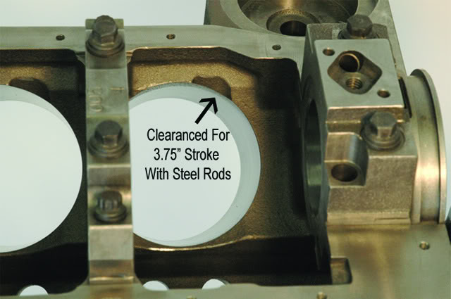
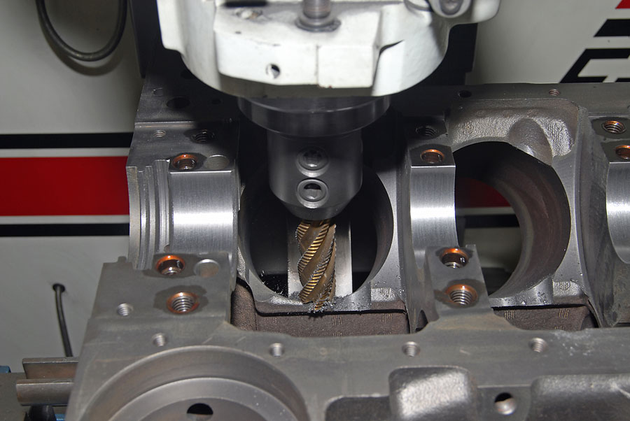
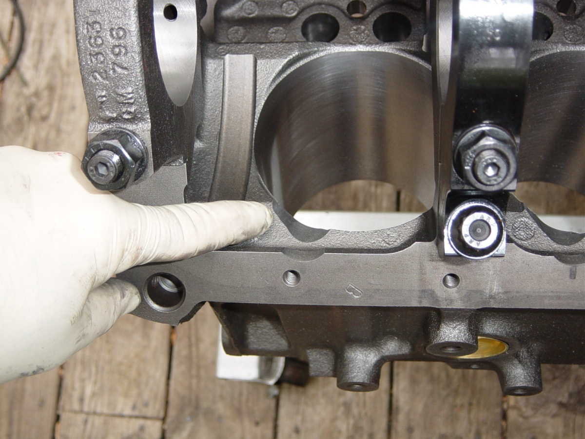
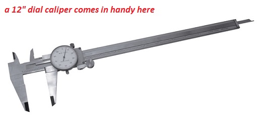
place a single rod/piston assembly with well oiled bearings and no rings installed on the first cylinders journal, and have the cam installed DOT TO DOT WITH THE TIMING SET INSTALLED, to check basic clearances ,now, rotate the crank thru a couple full rotations so the piston slides freely in the oiled bore, while you look closely at the rod too block clearance and rod too cam lobe clearance, if the cam lobes too close the edge of the rod bolt upper/edge of the bolt or rod itself needs to be filed/ground for clearance since you can,t grind the cam lobe, on the block the block gets clearanced ground, you want about a .060 minimum clearance. a large paper clip can be used as a crude feeler gauge,
a 1/2" dia carbide cutting burr in a die grinder can do it in seconds,once thats done you move that piston & rod to the next cylinder and repeat 7 more times, etc. don,t forget to clean up afterwards, and DON,T forget the rodand piston has the exhaust/intake valve and rod bearing radius fit correctly in only one dirrection on that cylinder
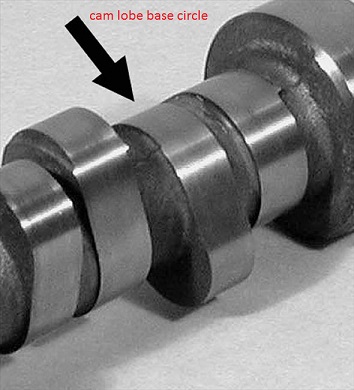
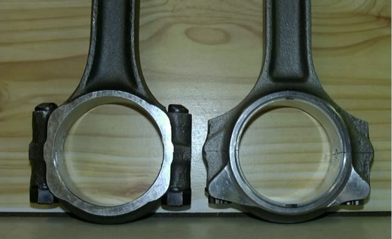
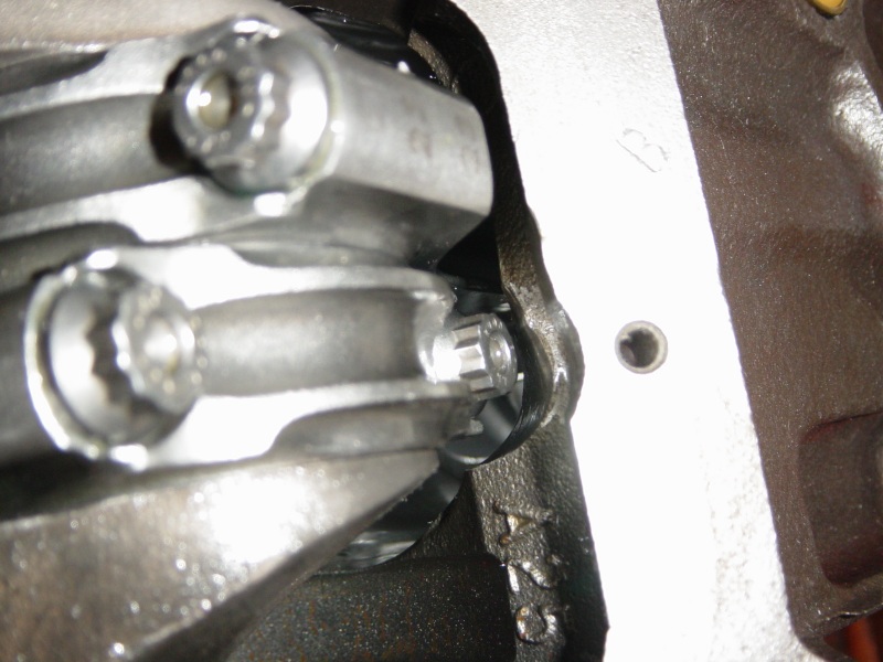
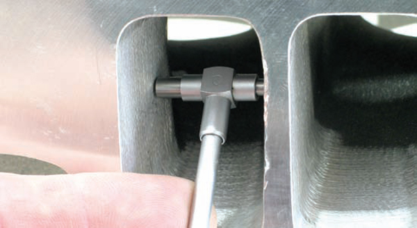
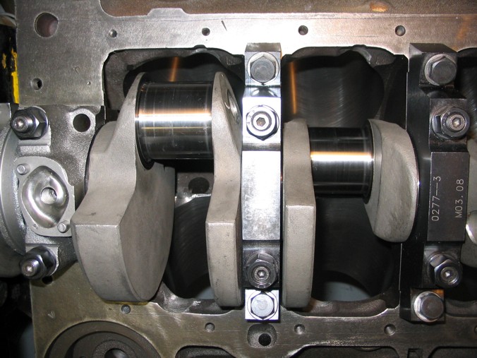
BEFORE
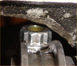
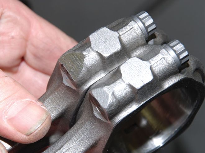
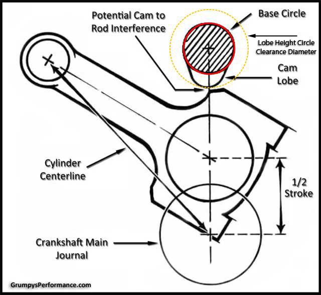
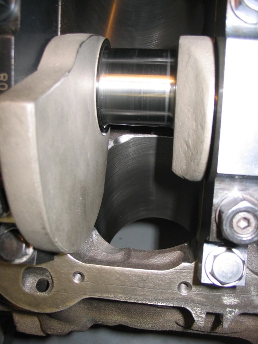
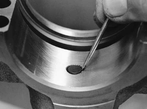
notice how the rod bolts come close to the cam bearings and cam lobes,as the pistons reach top dead canter in the bores, this clearance must be individually checked and should be no less than about .060 (generally you cam use a LARGE plastic tie-wrap
https://www.amazon.com/BuyCableTies...D=41U9CtmwOuL&preST=_SY300_QL70_&dpSrc=detail
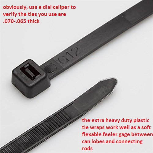
placed between the cam lobe and connecting rod bolts or connecting rod shoulder areas to check clearances as the soft tie-wrap will not damage the cam lobe while you verify clearances)
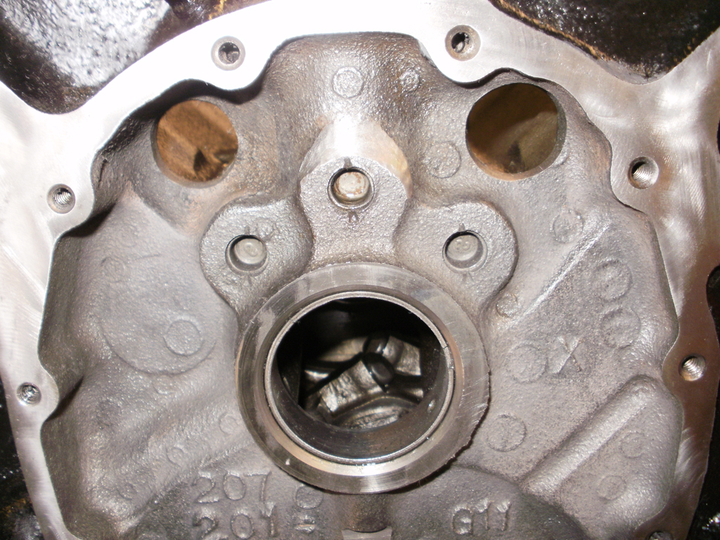
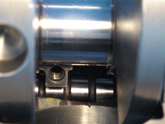
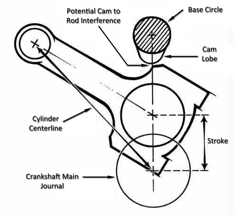
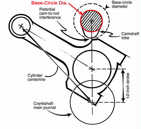
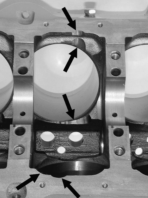
why you need to verify the cam to rod bolt clearance
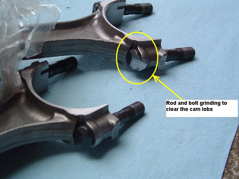
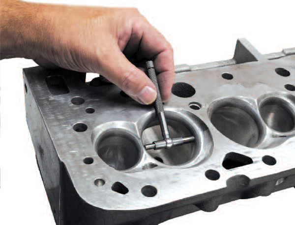
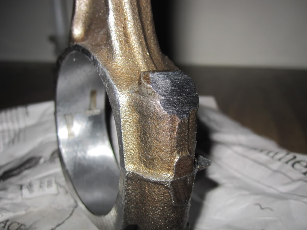
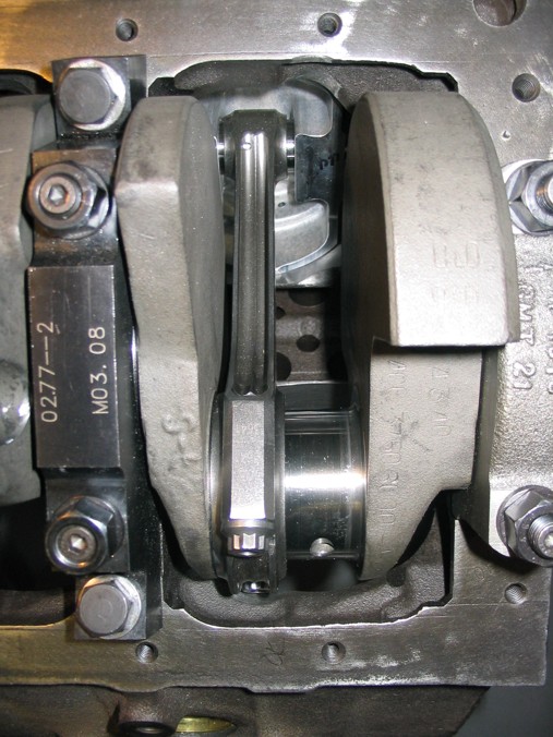
on some stroker applications SOME rods need to have the bolts ground for cam lobe clearance

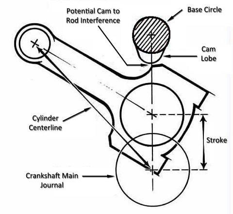
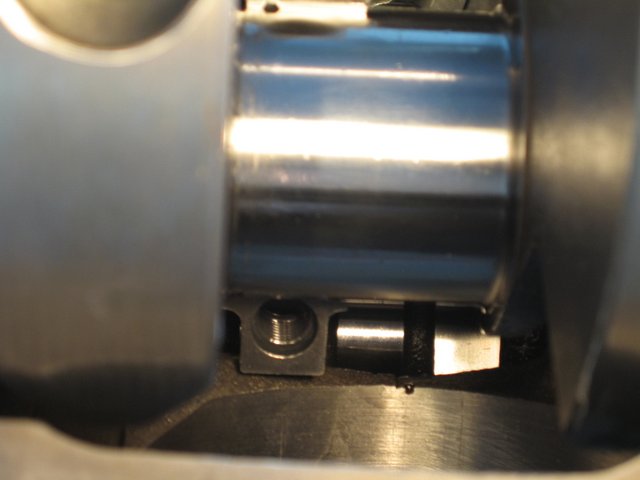
AFTER

Small Chevy
Fastener Type Torque Spec
7/16 in. outer main cap bolt 65 ft.-lbs.
7/16 in. inner main cap bolt 70 ft.-lbs.
3/8 in. outer main cap bolt 40 ft.-lbs.
11/32 in. connecting rod bolt 38-44 ft.-lbs.
3/8 in. connecting rod bolt 40-45 ft.-lbs.
Cylinder head bolts 65 ft.-lbs.
Screw-in rocker arm studs 50 ft.-lbs.
Intake manifold bolts (cast iron heads) 30 ft.-lbs.
Oil pump bolt 60-70 ft.-lbs.
Cam sprocket bolts 18-20 ft.-lbs.
Harmonic damper bolt 60 ft.-lbs.
Flywheel/Flexplate bolts 65 ft.-lbs.
Pressure plate bolts 35 ft.-lbs.
Bell housing bolts 25 ft.-lbs.
Exhaust manifold bolts 25 ft.-lbs.
Big Chevy
Fastener Type Torque Specs
Main cap bolt, 396-427 2-bolt 95 ft.-lbs.
Main cap bolt, 396-454 4-bolt (inner/outer) 110 ft.-lbs.
3/8 in. connecting rod bolt 50 ft.-lbs.
7/16 in. connecting rod bolt 67-73 ft.-lbs.
Cylinder head bolts, long 75 ft.-lbs.
Cylinder head bolts, short 65-68 ft.-lbs.
Screw-in rocker arm studs 50 ft.-lbs.
Intake manifold bolts (cast iron head) 25 ft.-lbs.
Oil pump bolt 65 ft.-lbs.
Cam sprocket bolts 20 ft.-lbs.
Harmonic damper bolt 85 ft.-lbs.
Flywheel/Flexplate bolts 60 ft.-lbs.
Pressure plate bolts 35 ft.-lbs.
Bell housing bolts 25 ft.-lbs.
Exhaust manifold bolts 20 ft.-lbs.


http://www.fourwheeler.com/techarticles ... to_11.html
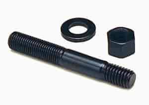
IF your going to use ARP main cap studs THE TORQUE SETTINGS ARE DIFFERANT than the orriginal BOLTS, the STUDS ARE STRONGER, BUT,you might also consider that main studs generally install after cleaning the threads in the block with a tap,blowing them dry with high pressure air, oiling the studs course threads with the thread sealant and fine threads end with the ARP thread lube, when you screw them into the block the full thread depth,by hand, then get backed out one turn, the main caps installed and the nuts torqued in stages to seat and hold the main caps, now LOOK at those STUDS the end in the block threads is SAE COURSE thread, the end your torqueing the nut on is SAE FINE THREAD with a much differant PITCH that requires less tq to give the same clamp loads

http://www.arp-bolts.com/catalog/Catalog.html
Why do they get backed out by one turn? I'm trying to think of the physics behind it, but I can't think of any good reason. What is the physics answer, Grumpy?
BE 100% SURE that the oil pump bolt or STUD doesn,t protrude past the inner main cap surface , because if it bears on the rear main bearing shell it will almost always result in a quickly failed rear bearing
the threads must bear evenly and align correctly with the studs centerline, for the stud to apply max loads over the total threaded surface ,the threaded section must be under tension alone and engage the total threaded surface in the block, if the stud is torqued into place, youve preloaded the threads bearing the load and they are partly under compressive loads ,your basically jacking the bottom of the threaded hole away from the threaded section, and appling THOUDANDS of lbs of extra stress to the blocks web area if you torque the threads to the same 100 ft lbs the original bolts were tightened to, the threads in the block will now have added stress once the full tension loads on the studs and main caps is applied by torqing the nuts on the studs ,theres added stress on the block, if the studs have bottomed out and are pushing on the bottom of the threaded hole making the block web area more likely to crack or the crank saddles to distort.
keep in mind FACTORY BOLTS are made slightly shorter to PREVENT the bolt tip bottoming out in the hole, but bolts cause wear on the threads because they are tightened while the bolts still advancing deeper into the threaded block, studs cause far less wear because they fully engage the threads bearing the loads before the tensive load is applied
heres what ARP says
"STUDS vs. BOLTS
ARP recommends the use of main studs over bolts whenever possible for several key reasons. First is the ability to obtain more accurate torque readings because studs don’t “twist†into the block. All clamping forces are on one axis. By the same token, there is less force exerted on the block threads, which contributes to improved block life (very critical on aluminum blocks). Finally, there are factors of easier engine assembly and proper alignment of caps every time"
ARP's instructions (for head studs)state that you should thread the studs into the block until they're hand-tight, but with the head on the block, this is difficult. Fortunately, ARP was thoughtful enough to incorporate a fitting for an Allen wrench into the head of each stud. So, using an Allen wrench, I threaded the studs into the head until I could no longer turn the wrench with two fingers. This method seems to have worked nicely
1. Clean and chase appropriate threads in
block to ensure proper thread engagement
and accurate torque readings.
2. All hardware (and caps) should be
cleaned and inspected prior to installation,
looking for any shipping damage or defects.
3. Screw studs into block, finger tight
ONLY. For permanent installation, apply
Loc-tite (or similar adhesive) sparingly
to threads. Be sure and install the caps
promptly before the cement sets to prevent
misalignment of studs in block.
1. Clean and chase appropriate threads in
block to ensure proper thread engagement
and accurate torque readings.
2. All hardware (and caps) should be
cleaned and inspected prior to installation,
looking for any shipping damage or defects.
There are a number of important considerations
when installing ARP main studs.
3. Screw studs into block, finger tight
ONLY. For permanent installation, apply
Loc-tite (or similar adhesive) sparingly
to threads. Be sure and install the caps
promptly before the cement sets to prevent
misalignment of studs in block.
First and foremost is making sure the
block and studs are as clean as possible.
Foreign matter and debris can easily affect
the quality of thread engagement and
cause erroneous torque readings. Do not
re-cut threads in the block – use the special
“chaser†taps as listed on page 87 of this catalog.
This will preserve the integrity of the
threads and provide better engagement.
Calibrate your torque wrench – even new
wrenches have been known to be off by as
much as 10 foot pounds! Use consistent
tightening techniques.
4. Install main caps, checking for binding
and misalignment. Lubricate threads, nuts
and washers with oil or ARP moly assembly
lubricant before installation. Note that torque
specs will vary by lubricant. Moly lube is
most consistent. Have block align honed.
5. Using the instructions provided with
the studs, tighten the nuts to proper
torque values three times. NOTE: If using
Loc-Tite or similar cement, proper preload
must be achieved prior to it setting up.
http://www.arp-bolts.com/FAQ/FAQ.html
I usually use this sealant (sparingly)on the course ends of main cap studs that screw in hand tight, and ESPECIALLY on head studs that enter water jackets
calculate horse power from intake port flow rates
http://www.wallaceracing.com/calcafhp.php
http://www.wallaceracing.com/calchpaf.php
http://www.wallaceracing.com/ca-calc.php
http://www.wallaceracing.com/max-rpm.php
http://www.wallaceracing.com/lpv.php
http://www.wallaceracing.com/chokepoint.php
http://www.wallaceracing.com/chokepoint-rpm.php
http://www.wallaceracing.com/area-under-curve.php
http://www.wallaceracing.com/piston-speed-velocity.php
http://www.wallaceracing.com/header_length.php
this thread and its related links and its contained sub links contain a huge amount of related useful info you can use
http://garage.grumpysperformance.com/index.php?threads/can-you-get-there-with-tpi.10494/#post-44284
http://garage.grumpysperformance.com/index.php?threads/c4-larger-intake-runners-l98-tpi.13785/
http://garage.grumpysperformance.co...m-dyno-results-and-other-info.433/#post-37683
http://garage.grumpysperformance.com/index.php?threads/hey-grumpy-do-i-need-bigger-injectors.5583/
http://garage.grumpysperformance.com/index.php?threads/port-speeds-and-area.333/
http://garage.grumpysperformance.com/index.php?threads/ideal-tpi-build.12203/
http://garage.grumpysperformance.co...sure-hurting-your-combo.495/page-2#post-35063
http://garage.grumpysperformance.com/index.php?threads/a-caveat-about-profiler-cylinder-heads.10065/
http://garage.grumpysperformance.co...gine-project-dart-shp.3814/page-35#post-23579
http://garage.grumpysperformance.com/index.php?threads/a-well-designed-c4-exhaust.786/#post-57392
http://garage.grumpysperformance.co...ther-efi-intake-manifold-info.431/#post-32491
http://garage.grumpysperformance.com/index.php?threads/tpi-throttle-body-size-48mm-52mm-58mm.546/
http://garage.grumpysperformance.com/index.php?threads/sources-for-tpi-parts-and-info.590/
http://garage.grumpysperformance.com/index.php?threads/bits-of-383-build-info.18/
http://garage.grumpysperformance.com/index.php?threads/my-current-corvettes-383-combo.430/[/quote]
http://www.permatex.com/products/Au.../Permatex_Super_300_Form-A-Gasket_Sealant.htm
http://garage.grumpysperformance.com/index.php?threads/my-current-corvettes-383-combo.430/
http://garage.grumpysperformance.com/index.php?threads/vintage-302-chevy.12071/page-9
http://garage.grumpysperformance.com/index.php?threads/a-well-designed-c4-exhaust.786/
keep in mind the course thread section is not being screwed in or the threads moved as the nut on the fine thread upper end is torqued to spec. and that thread requires the ARP thread lubricant to get the correct stretch and that stud needs to be cycled up to full torqure then released and retorqued,a minimum of three times to get the stretch/tq correct
a 1/2" dia carbide cutting burr in a die grinder can do it in seconds,once thats done you move that piston & rod to the next cylinder and repeat 7 more times, etc. don,t forget to clean up afterwards, and DON,T forget the rodand piston has the exhaust/intake valve and rod bearing radius fit correctly in only one dirrection on that cylinder
BEFORE
notice how the rod bolts come close to the cam bearings and cam lobes,as the pistons reach top dead canter in the bores, this clearance must be individually checked and should be no less than about .060 (generally you cam use a LARGE plastic tie-wrap
https://www.amazon.com/BuyCableTies...D=41U9CtmwOuL&preST=_SY300_QL70_&dpSrc=detail
why you need to verify the cam to rod bolt clearance
on some stroker applications SOME rods need to have the bolts ground for cam lobe clearance
AFTER
Small Chevy
Fastener Type Torque Spec
7/16 in. outer main cap bolt 65 ft.-lbs.
7/16 in. inner main cap bolt 70 ft.-lbs.
3/8 in. outer main cap bolt 40 ft.-lbs.
11/32 in. connecting rod bolt 38-44 ft.-lbs.
3/8 in. connecting rod bolt 40-45 ft.-lbs.
Cylinder head bolts 65 ft.-lbs.
Screw-in rocker arm studs 50 ft.-lbs.
Intake manifold bolts (cast iron heads) 30 ft.-lbs.
Oil pump bolt 60-70 ft.-lbs.
Cam sprocket bolts 18-20 ft.-lbs.
Harmonic damper bolt 60 ft.-lbs.
Flywheel/Flexplate bolts 65 ft.-lbs.
Pressure plate bolts 35 ft.-lbs.
Bell housing bolts 25 ft.-lbs.
Exhaust manifold bolts 25 ft.-lbs.
Big Chevy
Fastener Type Torque Specs
Main cap bolt, 396-427 2-bolt 95 ft.-lbs.
Main cap bolt, 396-454 4-bolt (inner/outer) 110 ft.-lbs.
3/8 in. connecting rod bolt 50 ft.-lbs.
7/16 in. connecting rod bolt 67-73 ft.-lbs.
Cylinder head bolts, long 75 ft.-lbs.
Cylinder head bolts, short 65-68 ft.-lbs.
Screw-in rocker arm studs 50 ft.-lbs.
Intake manifold bolts (cast iron head) 25 ft.-lbs.
Oil pump bolt 65 ft.-lbs.
Cam sprocket bolts 20 ft.-lbs.
Harmonic damper bolt 85 ft.-lbs.
Flywheel/Flexplate bolts 60 ft.-lbs.
Pressure plate bolts 35 ft.-lbs.
Bell housing bolts 25 ft.-lbs.
Exhaust manifold bolts 20 ft.-lbs.
http://www.fourwheeler.com/techarticles ... to_11.html
IF your going to use ARP main cap studs THE TORQUE SETTINGS ARE DIFFERANT than the orriginal BOLTS, the STUDS ARE STRONGER, BUT,you might also consider that main studs generally install after cleaning the threads in the block with a tap,blowing them dry with high pressure air, oiling the studs course threads with the thread sealant and fine threads end with the ARP thread lube, when you screw them into the block the full thread depth,by hand, then get backed out one turn, the main caps installed and the nuts torqued in stages to seat and hold the main caps, now LOOK at those STUDS the end in the block threads is SAE COURSE thread, the end your torqueing the nut on is SAE FINE THREAD with a much differant PITCH that requires less tq to give the same clamp loads
http://www.arp-bolts.com/catalog/Catalog.html
Why do they get backed out by one turn? I'm trying to think of the physics behind it, but I can't think of any good reason. What is the physics answer, Grumpy?
BE 100% SURE that the oil pump bolt or STUD doesn,t protrude past the inner main cap surface , because if it bears on the rear main bearing shell it will almost always result in a quickly failed rear bearing
the threads must bear evenly and align correctly with the studs centerline, for the stud to apply max loads over the total threaded surface ,the threaded section must be under tension alone and engage the total threaded surface in the block, if the stud is torqued into place, youve preloaded the threads bearing the load and they are partly under compressive loads ,your basically jacking the bottom of the threaded hole away from the threaded section, and appling THOUDANDS of lbs of extra stress to the blocks web area if you torque the threads to the same 100 ft lbs the original bolts were tightened to, the threads in the block will now have added stress once the full tension loads on the studs and main caps is applied by torqing the nuts on the studs ,theres added stress on the block, if the studs have bottomed out and are pushing on the bottom of the threaded hole making the block web area more likely to crack or the crank saddles to distort.
keep in mind FACTORY BOLTS are made slightly shorter to PREVENT the bolt tip bottoming out in the hole, but bolts cause wear on the threads because they are tightened while the bolts still advancing deeper into the threaded block, studs cause far less wear because they fully engage the threads bearing the loads before the tensive load is applied
heres what ARP says
"STUDS vs. BOLTS
ARP recommends the use of main studs over bolts whenever possible for several key reasons. First is the ability to obtain more accurate torque readings because studs don’t “twist†into the block. All clamping forces are on one axis. By the same token, there is less force exerted on the block threads, which contributes to improved block life (very critical on aluminum blocks). Finally, there are factors of easier engine assembly and proper alignment of caps every time"
ARP's instructions (for head studs)state that you should thread the studs into the block until they're hand-tight, but with the head on the block, this is difficult. Fortunately, ARP was thoughtful enough to incorporate a fitting for an Allen wrench into the head of each stud. So, using an Allen wrench, I threaded the studs into the head until I could no longer turn the wrench with two fingers. This method seems to have worked nicely
1. Clean and chase appropriate threads in
block to ensure proper thread engagement
and accurate torque readings.
2. All hardware (and caps) should be
cleaned and inspected prior to installation,
looking for any shipping damage or defects.
3. Screw studs into block, finger tight
ONLY. For permanent installation, apply
Loc-tite (or similar adhesive) sparingly
to threads. Be sure and install the caps
promptly before the cement sets to prevent
misalignment of studs in block.
1. Clean and chase appropriate threads in
block to ensure proper thread engagement
and accurate torque readings.
2. All hardware (and caps) should be
cleaned and inspected prior to installation,
looking for any shipping damage or defects.
There are a number of important considerations
when installing ARP main studs.
3. Screw studs into block, finger tight
ONLY. For permanent installation, apply
Loc-tite (or similar adhesive) sparingly
to threads. Be sure and install the caps
promptly before the cement sets to prevent
misalignment of studs in block.
First and foremost is making sure the
block and studs are as clean as possible.
Foreign matter and debris can easily affect
the quality of thread engagement and
cause erroneous torque readings. Do not
re-cut threads in the block – use the special
“chaser†taps as listed on page 87 of this catalog.
This will preserve the integrity of the
threads and provide better engagement.
Calibrate your torque wrench – even new
wrenches have been known to be off by as
much as 10 foot pounds! Use consistent
tightening techniques.
4. Install main caps, checking for binding
and misalignment. Lubricate threads, nuts
and washers with oil or ARP moly assembly
lubricant before installation. Note that torque
specs will vary by lubricant. Moly lube is
most consistent. Have block align honed.
5. Using the instructions provided with
the studs, tighten the nuts to proper
torque values three times. NOTE: If using
Loc-Tite or similar cement, proper preload
must be achieved prior to it setting up.
http://www.arp-bolts.com/FAQ/FAQ.html
I usually use this sealant (sparingly)on the course ends of main cap studs that screw in hand tight, and ESPECIALLY on head studs that enter water jackets
calculate horse power from intake port flow rates
http://www.wallaceracing.com/calcafhp.php
http://www.wallaceracing.com/calchpaf.php
http://www.wallaceracing.com/ca-calc.php
http://www.wallaceracing.com/max-rpm.php
http://www.wallaceracing.com/lpv.php
http://www.wallaceracing.com/chokepoint.php
http://www.wallaceracing.com/chokepoint-rpm.php
http://www.wallaceracing.com/area-under-curve.php
http://www.wallaceracing.com/piston-speed-velocity.php
http://www.wallaceracing.com/header_length.php
this thread and its related links and its contained sub links contain a huge amount of related useful info you can use
TBucket Engine Project (Dart SHP)
It's time to get this party started! Last night I picked up some of my parts, the only thing left to come in, is the Mahle piston and rings. This is just the first order, mostly the things I need right now to get started. It's been over ten years since I've driven this car and I am SOOO ready to...
garage.grumpysperformance.com
http://garage.grumpysperformance.com/index.php?threads/can-you-get-there-with-tpi.10494/#post-44284
http://garage.grumpysperformance.com/index.php?threads/c4-larger-intake-runners-l98-tpi.13785/
http://garage.grumpysperformance.co...m-dyno-results-and-other-info.433/#post-37683
http://garage.grumpysperformance.com/index.php?threads/hey-grumpy-do-i-need-bigger-injectors.5583/
http://garage.grumpysperformance.com/index.php?threads/port-speeds-and-area.333/
http://garage.grumpysperformance.com/index.php?threads/ideal-tpi-build.12203/
http://garage.grumpysperformance.co...sure-hurting-your-combo.495/page-2#post-35063
http://garage.grumpysperformance.com/index.php?threads/a-caveat-about-profiler-cylinder-heads.10065/
http://garage.grumpysperformance.co...gine-project-dart-shp.3814/page-35#post-23579
http://garage.grumpysperformance.com/index.php?threads/a-well-designed-c4-exhaust.786/#post-57392
http://garage.grumpysperformance.co...ther-efi-intake-manifold-info.431/#post-32491
http://garage.grumpysperformance.com/index.php?threads/tpi-throttle-body-size-48mm-52mm-58mm.546/
http://garage.grumpysperformance.com/index.php?threads/sources-for-tpi-parts-and-info.590/
http://garage.grumpysperformance.com/index.php?threads/bits-of-383-build-info.18/
http://garage.grumpysperformance.com/index.php?threads/my-current-corvettes-383-combo.430/[/quote]
http://www.permatex.com/products/Au.../Permatex_Super_300_Form-A-Gasket_Sealant.htm
http://garage.grumpysperformance.com/index.php?threads/my-current-corvettes-383-combo.430/
http://garage.grumpysperformance.com/index.php?threads/vintage-302-chevy.12071/page-9
http://garage.grumpysperformance.com/index.php?threads/a-well-designed-c4-exhaust.786/
keep in mind the course thread section is not being screwed in or the threads moved as the nut on the fine thread upper end is torqued to spec. and that thread requires the ARP thread lubricant to get the correct stretch and that stud needs to be cycled up to full torqure then released and retorqued,a minimum of three times to get the stretch/tq correct
Last edited by a moderator: