read thru each link as theres a great deal of useful related info in each
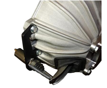
most hydraulic throw out bearings are designed to expand and contract a known distance ,that might or may not require a spacer to allow the hydraulic throw out bearing to depress the clutch pressure plate enough to release the clutch disk and contract enough to remain about 1/8" back away from the pressure plate when its not expanded
http://www.corvettefever.com/howto/84759/index.html
http://www.torcavettes.com/tech/ClutchHydraulics.htm
http://rangeracceleration.com/Clutch_Care.html
http://tiltonracing.com/product/6000-series-hydraulic-release-bearings/
http://www.hotrodhydraulics.com/GM-Year.htm
http://keislerauto.com/vmchk/gm/gm-part ... ducts.html
http://www.novak-adapt.com/catalog/kit_hcr3.htm
http://www.novak-adapt.com/catalog/kit_hcrc.htm
http://www.cbperformance.com/catalog.asp?ProductID=1228
http://www.zfdoc.com/clutch_hydraulic.htm
dot 4 brake fluid changed out about every 2 years, or if it becomes cloudy, is the preferred fluid in the clutch
FROMZR51 Performance
http://www.ecklers.com/master-cylinder- ... ool-1.html
"C4 MN6 Clutch Hydraulic System
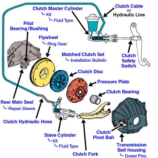
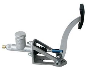
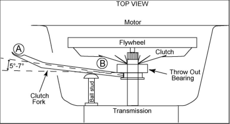
The Clutch Hydraulic System is responsible for the momentary disengagement of the driveline power supply allowing the transmission synchronizers to operate within their intended design parameters. A healthy clutch hydraulic system should yield 0.290" to 0.315" of throw-out bearing travel with each 6.5 inches of clutch pedal travel. When shifting the ZF S6-40 6-speed manual transmission, the clutch pedal must be cycled completely to the floor. Correct seat distance from the pedals should leave less than 1/2 inch clearance between left knee cap and the hush panel above the left knee. This ensures ample reserve extension range of the clutch leg with better distributing of the work load between the knee and ankle joint. When the seat is positioned to far back from the pedals, the knee joint becomes more fully extended requiring more ankle joint extension to complete a full clutch pedal cycle.
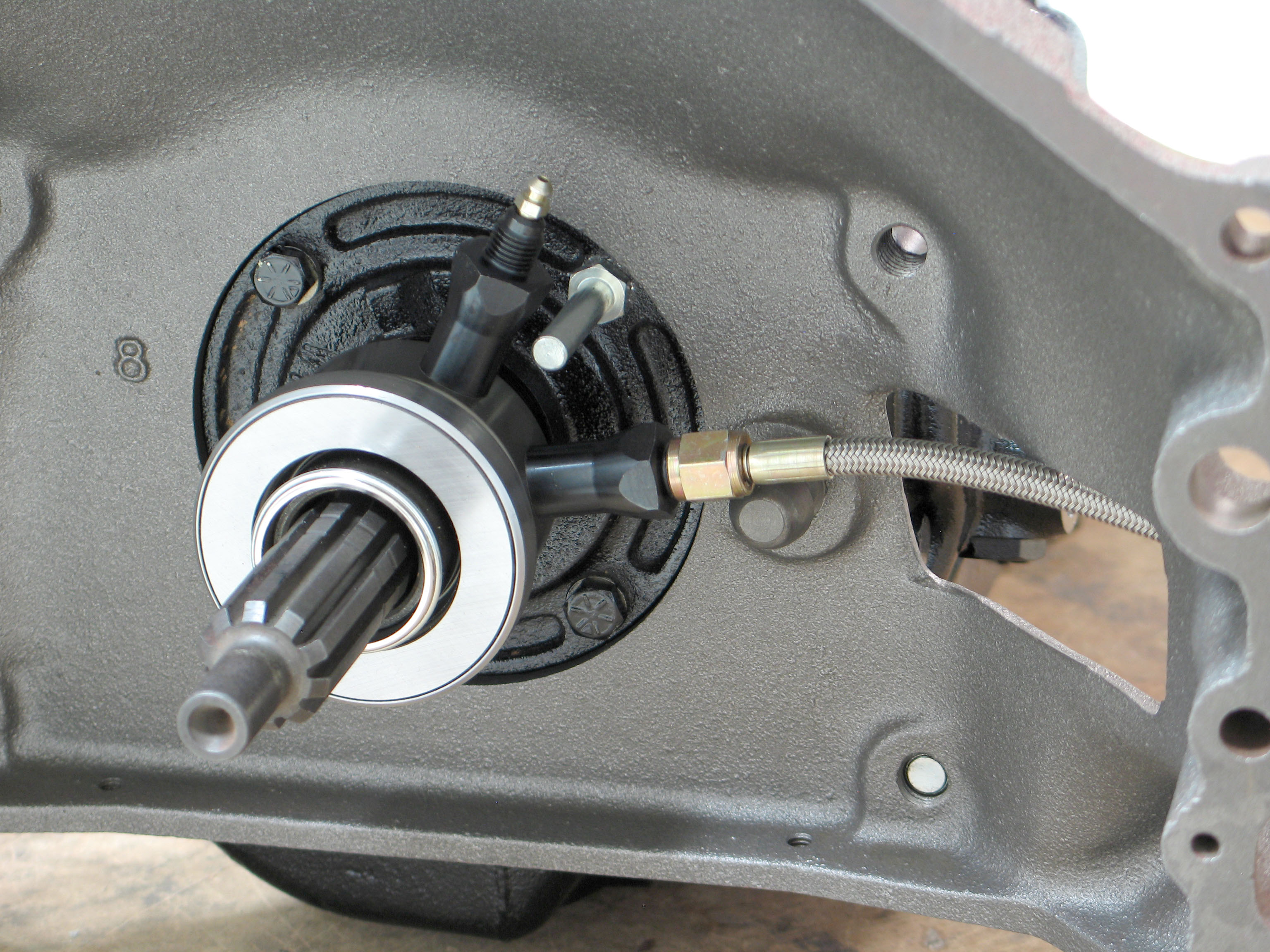
The actuator cylinder piston seal, when new, has 5 micro-ridges on the lip seal. These micro-ridges reduce surface tension during operation allowing the seal to glide/travel smoothly within the bore. When these micro-ridges wear away, which they always eventually do, the surface tension increases causing the seal to eventually stop short and pucker instead of traveling as far down the bore as when new. The same goes with the performance of the master cylinder piston bore seal. Compound these conditions with additional particle debree from the decomposing hydraulic feed line inner wall surface, or decomposing reservoir bulkhead seal, which by the way, is what causes the clear hydraulic fluid to quickly turn black, and you have a significantly degraded condition of the clutch hydraulic system.
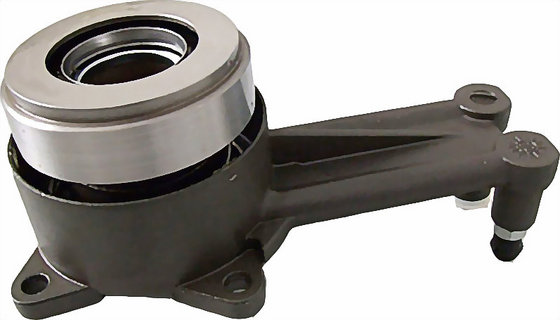
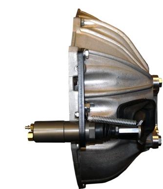
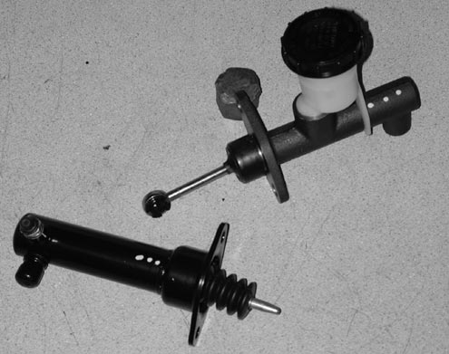
The '89-'96 C4 Corvette clutch hydraulic system is composed of a master cylinder, hydraulic feed line and an actuator (slave cylinder). These particular systems are somewhat prone to developing conditions of degraded levels of operation. For system testing see Clutch Hydraulic System Test below. When replacing the Actuator cylinder, it is recommended that the clutch master cylinder be replaced as a pair. The actuator bleeder screw already equipped with replacement actuators is no longer available separately from GM. When Bleeding the Clutch Hydraulic System, we recommend using Valvoline Dot 3 Dot4 Full Synthetic Brake Fluid. NOTE: On '90-'96 Corvettes, the Engine Control Module (10mm nut fasteners) located in the engine compartment must be moved out of the way in order to gain access to the clutch master cylinder hydraulic fluid reservoir.
R&R of the Clutch Hydraulic System:
Removal of the battery panel and battery are necessary to service the clutch hydraulic master cylinder. Unhooking the clutch hydraulic master cylinder linkage must be done from inside the car under the dash. If you have the car up on jack stands and the driver's side hush panel has been removed, the clip can be accessed from directly below while visually acquired clip by looking through the hood release handle. Ample lighting is recommended. It's not that bad of a job as long as you have a long regular blade screwdriver and extra long needle nose pliers. The key is to have the vehicle up on jack stands so you can sit/kneel on the floor and have your eye level be at the lower door jam height looking up through the hood release socket.
Bleeding the Clutch Hydraulic System:
There are two versions ('89-'90, '91-'96) of clutch hydraulic Actuators (slave cylinder) for the C4 Corvette. The '89-'90 Clutch Hydraulic System actuator has the feed tube located at 12 o'clock and bleed tube at 10 o'clock. The '91 - '96 Clutch Hydraulic System Actuator has the feed tube located at 12 o'clock and bleed tube at 6 o'clock. This redesign makes the bleed fitting more accessible. Unfortunately, the bleeder horn repositioned to the 6 o'clock position complicates the bleed process due to the fact that air bubbles rise therefore rendering the reverse bleed method as being most effective approach to bleeding the system. Reverse bleeding is the process of forcing fluid into the system at the lowest point forcing the fluid back and upwards to the master cylinder fluid reservoir. This method will only be successful if no air is allowed to enter into the system during bleeding. WARNING: When pressure bleeding any hydraulic system it is necessary to provide the best seal possible around the bleeder fitting threads so as not to inadvertently draw in air as fluid is being pumped into the system. To achieve this affect, remove, clean and carefully apply 3 to 4 wraps of Teflon tape to the thread area only of the bleeder screw. Failure to follow this procedure will result in an improperly bled hydraulic system due to air ingestion during the bleeding process. NOTE: The best method that I have found so far in reverse bleeding these types of systems is to bleed the system until the fluid is clean and void of air bubbles, tighten bleeder screw, cycle the clutch pedal 50 times at varying rates and stroke depths, then perform one additional bleed before securing the tightening the bleeder screw to 18 Nm (13 lbs. ft.). Although bleeding can be done more simply by opening the Actuator bleeder and letting gravity draw fluid through the system, the following bleeding method will provide a more thorough evacuation of old fluid and particle accumulations.
'89-'90 Clutch Hydraulic System: The vehicle must be level front-to-back and left-to-right can be from level on up to 2 feet higher than the right side. The bleeding process is most effectively done by conventional method where one person actuates the clutch pedal while another opens and closes the bleeder after the pedal is depressed to the floor and before the pedal is let back up. After the bleeding process is complete, fill the reservoir to 1/16" below the "Low" mark so that when the "clean and dry" moisture barrier is re-inserted and lid screwed on, the fluid level remains between the LOW and HI mark. This set up method provides the best level of atmospheric pressure isolation with in the hydraulic system.
'91-'96 Clutch Hydraulic System: The vehicle must be in a level position both front-to-back and left-to-right when bleeding. The bleeding process is best done with a pressure bleeding system such as a "Phoenix Injector" or "Mighty-Vac". Bleeding of the system is best done by reverse flowing clean/new fluid, feeding the Actuator bleed horn located at the 6 o'clock position. Reverse pressure bleeding pushes the used fluid back upwards from the Actuator bleeder through the system on up to the reservoir. After the bleeding process is complete, fill the reservoir to 1/16" below the "Low" mark so that when the "clean and dry" moisture barrier is re-inserted and lid screwed on, the fluid level remains between the LOW and HI mark. This set up method provides the best atmospheric pressure isolation of the hydraulic system. WARNING: When pressure bleeding any hydraulic system it is necessary to provide the best seal possible around the bleeder fitting threads so as not to inadvertently draw in air as fluid is being pumped into the system. To achieve this affect, remove, clean and carefully apply 6 or 7 wraps of Teflon tape to the thread area only of the bleeder screw. Failure to follow this procedure will result in an improperly bled hydraulic system due to air ingestion during the bleeding process. NOTE: The best method that I have found so far in reverse bleeding these types of systems is to bleed the system until the fluid is clean and void of air bubbles, tighten bleeder screw, cycle the clutch pedal 50 times at varying rates and stroke depths, then perform one additional bleed before securing the tightening the bleeder screw to 18 Nm (13 lbs. ft.). Although bleeding can be done more simply by opening the Actuator bleeder and letting gravity draw fluid through the system, the following bleeding method will provide a more thorough evacuation of old fluid and particle accumulations.
Operational Checkout: Regardless of driveline temperature, when you fully depress the clutch pedal and actuate the shift lever into gear the forward/backward effort required to move the lever into gear should feel fairly smooth and free of notches. Note: The side-to-side gate-alignment effort of moving the shift lever is not affected by the operational condition of the hydraulic clutch. If component replacement and repeated bleeding does not improve the shifting quality, contact us for further corrective action suggestions.
Clutch Hydraulic Part Numbers and Current Prices (January 2008):
Note: All new slave cylinders come with a new bleeder screw.
('89-'96) Clutch hydraulic master cylinder GM P/N 10147953 (GM List $216.05)
('89-'90) Hydraulic Feed Line GM P/N 10147949 (Discontinued GM item)
('91-'96) Hydraulic Feed Line GM P/N 12509314 (GM List $140.64)
('89-'90) Slave Cylinder GM P/N 10147948 (Discontinued GM item)
('91-'96) Slave Cylinder GM P/N 12509313 (GM List $181.72)
('89-'96) Bleeder Screw, Actuator GM P/N 10181244 (Discontinued GM item)
Clutch Hydraulic System Test:
The C4 clutch hydraulic system is self-bleeding and non-adjustable. Cycling the clutch pedal multiple times while on a level grade before driving will promote displacement of any trapped air pockets formed within either cylinder assembly while vehicle was not in use. Providing that the threaded fittings of the hydraulic line between the clutch master and slave cylinder are leak free, the only 3 areas of the system in which air can enter into is the slave cylinder assembly seal, the master cylinder assembly seal or the fluid reservoir inlet (when empty). In order for an air pocket to develop within a given cylinder assembly, the cylinder must be tilted at an angle where the potential leak is at a lower point of the vessel. Both the master and slave cylinder assemblies are horizontally mounted. The master cylinder assembly faces forward and the slave cylinder assembly faces rearward. When the vehicle is parked facing uphill, the clutch hydraulic master cylinder is more likely to develop an air pocket. When the vehicle is parked facing downhill, the clutch actuator cylinder is more likely to develop an air pocket.
To put this type of operational condition more into rate-of-wear perspective, shifting with a degraded hydraulic clutch system will increase the rate of phosphorous-bronze mass worn from the synchronizers at 10 to 20 times faster than during shifting with a healthy hydraulic clutch system. When left uncorrected, this condition will eventually deplete the wear-range of the synchronizers to the point where gear clash occurs (especially at higher RPM gear shifts) when shifting gears.
It is possible that the actuator cylinder can develop a buildup of deposits in the barrel at the fully depressed piston seal position causing a hang up of the actuator seal under mild depression rate cycling of the cylinder. Rapid and complete depression of the clutch will cause the seal to stretch momentarily at the fully depressed end of the cycle causing the actuation stroke to cycle deeper than when cycling the clutch at a slower rate. This condition may be corrected with thorough bleeding of the system.
To date we have rebuilt 218 ZF S6-40 transmissions. I would say that 70% of those units were primarily damaged while operating with some type of degraded hydraulic clutch condition. Power shifting while under these conditions can cause catastrophic damage to the synchronizers and their related components.
LEAK DOWN TEST OF THE CLUTCH
MASTER AND SLAVE HYDRAULIC CYLINDERS
How to check out the operational condition of the hydraulic clutch system:
1. Thoroughly bleed the system with Valvoline Dot3 Dot4 Full-Synthetic brake fluid.
2. Simulate the vehicle being parked on an incline for 12-24 hours with the front end at least 1 foot higher than the rear.
3. Lower the vehicle if raised for test. Note: Do not cycle (pump) the clutch before next step.
4. With the clutch pedal remaining depressed, start the vehicle.
5. Try to put it into reverse when it first gets started (cold).
Note: Difficulty getting into reverse when in this condition indicates that the clutch master cylinder is not at 100%.
6. Repeat steps 1-5 of this procedure except with rear end raised.
Note: This will be the leak down test for the slave cylinder.
The best advice I can give is:
1) Pay attention to the clutch hydraulic system. 85% of the ZF 6-speeds (S6-40) that come across my bench are in for service due to early failure due to improperly maintained hydraulic clutch systems operating in a degraded condition. Don't hesitate to replace the slave cylinder when it no longer bleeds out and (doesn't trap air/moisture for several months) operates perfectly. Prepare to replace the clutch master hydraulic cylinder once for every 2 slave cylinder replacements. The hydraulic clutch system must always operate in the 97+% efficiency range to provide for normal transmission life expectancy (75,000 - 150,000 miles) based on demand usage.
2) Get up into the pedals by inching your seat up a bit closer than normal.. Your shift sequence naturally gets tighter when your clutch leg has more bend in the knee and ankle joints. This allows you to exert more spring action ensuring that the clutch pedal contacts bounces back off the firewall pad. "