calculating ideal port size

grumpyvette

Administrator
Staff member
http://www.rbracing-rsr.com/runnertorquecalc.html

http://www.compcams.com/Community/Articles/Details.asp?ID=1737510521

http://users.erols.com/srweiss/tablehdc.htm

http://www.thecarburetorshop.com/Carburetorsizeselection.htm

http://www.wallaceracing.com/runnertorquecalc.php

http://www.wallaceracing.com/intake-runner-length.php

http://www.wallaceracing.com/lpv.php

http://www.wallaceracing.com/ca-calc.php

http://www.jsme.or.jp/esd/COMODIA-Procs ... 4_P535.pdf

http://www.malcams.com/legacy/misc/headflow.htm

http://victorylibrary.com/mopar/intake-tech-c.htm

http://www.4secondsflat.com/Carb_CFM_Calculator.html
volumetric.gif

heres a chart FROM THE BOOK,HOW TO BUILD BIG-INCH CHEVY SMALL BLOCKS with some common cross sectional port sizes
(measured at the smallest part of the ports)
...........................sq inches........port cc
edelbrock performer rpm ....1.43.............170
vortec......................1.66.............170
tfs195......................1.93.............195
afr 180.....................1.93.............180
afr 195.....................1.98.............195
afr 210.....................2.05.............210
dart pro 200................2.06.............200
dart pro 215................2.14.............215
brodix track 1 .............2.30.............221
dart pro 1 230..............2.40.............230
edelbrock 23 high port .....2.53.............238
edelbrock 18 deg............2.71.............266
tfs 18 deg..................2.80.............250


DYNO DON POSTED THIS BIT OF INFO

"AFR 195 Eliminators
actual cc's in the intake port.....184
cross section area...2.13 sq.in
Flow spec's.....281/221

AFR 195 comp Eliminators
actual cc's ....189
cross section...2.15 sq.in
Flow spec's...306/235

Trick Flow 195 K D
before porting actual cc's....185
after porting ...188
cross section....2.13 sq.in
Flow spec's....270/210

Edelbrock Etec 200's
actual cc's before porting N/A
after porting....197
cross section...2.13
Flow spec's...270/218


Potential HP based on Airflow (Hot Rod, Jun '99, p74):
Airflow at 28" of water x 0.257 x number of cylinders = potential HP
or required airflow based on HP:
HP / 0.257 / cylinders = required airflow

SO HOW MUCH WOULD YOU LIKELY GAIN FROM A HEAD SWAP THAT ALLOWED YOUR HEAD FLOW ON A SERIOUS BIG BLOCK TO JUMP FROM LETS SAY 370CFM to lets say 425CFM?

A HARD number that has held pretty true for conventional BBC on gasoline , with compression ratios up ner optimum, near 12:1-13.5:1 to predict peak HP from head flow is .25-.27 x intake flow rate @ 28" x 8 (# of cyls). Like others have said, a lot of variables,like efficiency of exhaust scavenging,compression ratio and valve lift VS port potential flow, but it has been within 20 or 30 HP on several different BBC's I've seen being dynoed.

For example, I had an 357 AFR-headed 540, the heads flow 425cfm @ 28". So 425 x .27 x 8 = 918 HP. It made 940. Another motor calc'd at 1030, made 1040 on the dyno.

Using the same logic, 50 cfm x .27 x 8 = 108 hp. It's not that simple, it depends on combination, how optimized everything is etc. But if you are looking for round numbers, 50-75 hp is probably realistic, 100 hp possible


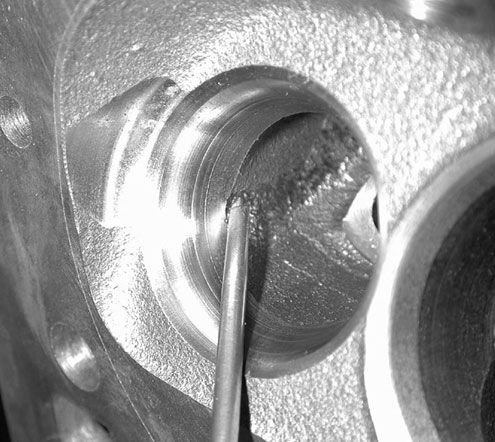
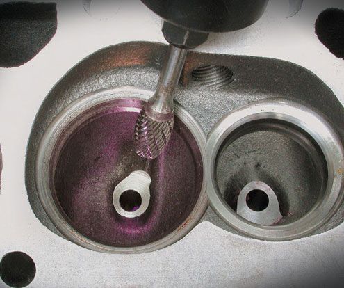
ITS A COMMON MISCONCEPTION,THAT YOU MEASURE PORT CROSS SECTION AT THE PORT ENTRANCE,BUT ITS NOT the port area at the entrance , you need to use in the calcs, ITS the MINIMAL port cross section at the SMALLEST point in the port, usually near the push rod area.
LIKE a funnel, its not the largest part of the opening but the smallest thats the restriction to flow

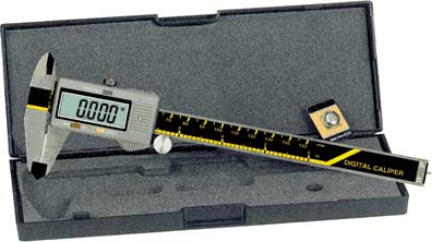
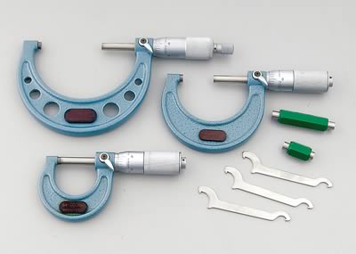
SO HOW do you MEASURE THEN??

http://www.harborfreight.com/cpi/ctaf/displayitem.taf?Itemnumber=5649
05649.gif


http://store.summitracing.com/partdetail.asp?autofilter=1&part=SUM-900014&N=700+115&autoview=sku

sum-900014_cp.jpg


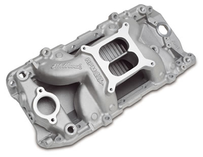
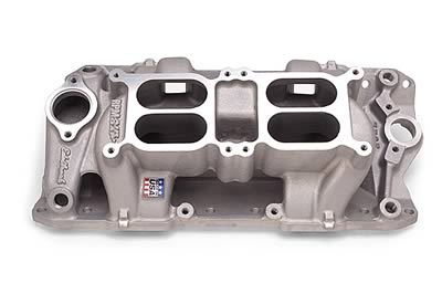
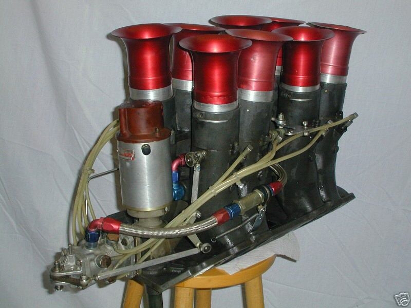
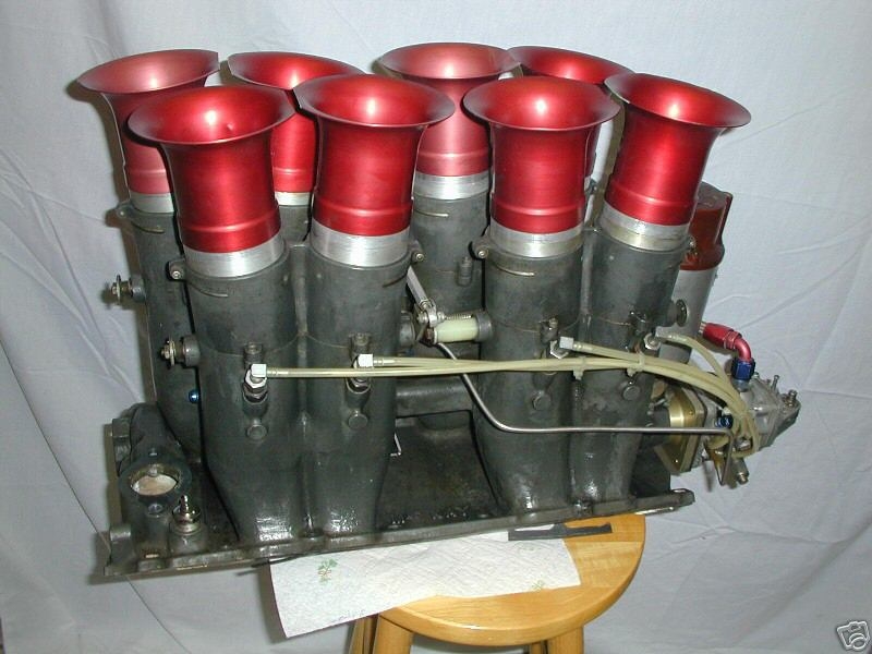
runner LENGTH and CROSS SECTION plus PLENUM VOLUME (if there is a plenum)effects the intake harmonics and how effectively you can ram tune the intake runner charge to fill the cylinders, and don,t forget exhaust scavaging , compression ratio and cam timing, and valve curtain area,and drive train gearing must match the intended combos effective operational power band

http://victorylibrary.com/mopar/intake-tech.htm

http://www.rbracing-rsr.com/runnertorquecalc.html

http://www.bgsoflex.com/intakeln.html

http://www.engr.colostate.edu/~allan/fluids/page7/PipeLength/pipe.html
 
Last edited by a moderator:
http://www.hotrod.com/techarticles/engi ... index.html

porting can help

viewtopic.php?f=52&t=462


most guys use a couple layers of duct tape, as a protective shield when doing a pocket port work with an air die grinder,and carbide burr,but just try not to get carried away and be careful and remember to mark and replace the valves in their original locations

http://www.harborfreight.com/cpi/ctaf/d ... mber=99698
99698.gif


http://www.carbideselect.com/burshpescuts.php

this model die grinder is surprisingly good quality for a disposable throw away die grinder,and usually last for more than two cylinder heads, its a true bargain, if it lasts only for two! don,t even think about use of the hard stone grinding bits they shatter and are cheap crap, get real carbide burrs

BUY & WEAR THE MANDATORY SAFETY GOGGLES, and face shield as tiny bits of crap get to flying around at times

http://www.harborfreight.com/cpi/ctaf/d ... mber=66538

http://www.harborfreight.com/cpi/ctaf/d ... umber=4652

http://garage.grumpysperformance.co...e-stock-tpi-engine-components.1509/#post-3459

the idea of running individual intake runners to each carb venturie on a tunnel ram intake to reduce plenum area, and increase the rapid response to throttle changes comes up fairly often,but it won,t work unless all the carburetor venturies , both flow equal quantities of fuel/air mix all the time at the same fuel/air ratio, and all the throttle blades open at exactly the same rate. which is only something a few carbs are capable of doing and most of those are Holley dominator based designs designed for that application. Id also point out that the plenum under the carbs allows a great deal of flow sharing that allows you to feed a single intake runners from more than a single carb venturie, thats critical, because in almost all cases a single four barrel carbs single venturie is too small in diameter to effectively supply the needs of an engines cylinders.
If you do the research youll quickly find out about port stall speeds, and effective port cross sectional areas.
ID certainly point out that a common 4 barrel carbs rated flow is meassured on a standard industry vacuum reading of 1.5" or mercury , and a change in vacuum changes the effective air flow!
think about that....
that single 600 cfm rated carburetor , you were using ,might see 17 inches of plenum vacume on a rpm air gap single carb intake!
put the same carb, on the same engine, with an identical second carb, bolted on a dual quad manifold, and youve effectively doubled the venturie surface area, effectively reducing the plenum vacuum at W.O.T. so theres no question that the carbs will need to be re-tuned from the way they were set-up to function correctly

edlb-7561v.jpg

edl-7525.jpg


http://wallaceracing.com/intakecfm.php


http://www.wallaceracing.com/runnertorquecalc.php

http://www.wallaceracing.com/ca-calc.php

http://www.highperformancepontiac.com/t ... index.html

http://www.highperformancepontiac.com/t ... index.html


Determining Port Velocity and Volume
Determining air velocity is a useful part of testing. It is calculated as follows:
V = 1096.7 * H/d
Where:
V= Velocity in feet per minute
H= Pressure drop across test piece in inches of water (28 inches of water column being a standard)
d= density of air in pounds per cubic foot ( .075 pounds per cubic foot at standard conditions )
This represents the highest speed of the air in the flow path, at or near the section of minimum area (i.e. through the valve seat at low values of L/D, through the pushrod pinch, or minimum intake cross section, which ever is smaller).
Once velocity has been calculated, the volume can be calculated by multiplying the velocity by the minimum cross section area. Since we measure flow in cubic feet per minute, we use the first formula and divide by the cubic feet of cross section area: If we have an average cross section of 2.1 square inches:
Volume = Velocity (21,190 fpm) x Area (2.1 sqin x 1 sqft/144 sqin - converts sqin to sqft) = 309 cfm @ 28 inches
Since we use feet per second in the flow measurement of ports the formula above the equation becomes:
V = 1096.7/60 (18.278) * H/d
V = 353 feet per second (fps)
This should be the highest velocity measured in a port flow tested at 28 inches of water column.

Mean Piston speed in linear ft/sec from stroke in inches & RPM (David Vizard)

We want to find the average speed of a piston traveling up or down between TDC and BDC. Though it should be emphasized the piston speed peaks much faster than the value we will find, and it slows to a stop and perhaps reverses slightly at TDC & BDC, this mean (average) velocity figure is highly useful as a comparator. It's also useful to note for later that because of the secondary-linkage effect of the connecting rod, the piston spends more time in the lower 180* of the rotation.

Conversion of measurement units: stroke in inches divided by 12 to get stroke in feet : s/12 = stroke in feet

then take the stroke times two because the piston travels
the stroke's distance twice in a revolution, and by convention we measure rotational speed by full revolutions : ( S/12 ) x 2 or,

by taking the 2 inside the brackets, we get ( S /6 )

Then, since by convention, we measure rotational speed in automotives in a per minute format,
and we use a per second format for gas velocity, we need the revolutions each second, i.e. per
one sixtieth of a minute ,
so : ( S/6 ) x RPM/60 or cleaning up the formula by basic algebra :

S/360 x rpm = average speed of a piston traveling up or down between TDC and BDC


Mean Gas speed from piston speed (above) and "area/cross section quotient":

We want to find the average gas velocity over a stroke of the piston- a half revolution of the crank, assuming we have the cross-sectional area of a header tube, or of an intake or exhaust port. The latter can be approximated by measuring centerline length and port volume, and subsequently converting the units of measure to match the units for the motor bore area, in this case, square inches.

There are several ways of accumulating the measurements required, but the simplest starts with bore area which we are likely able to calculate easily, either working from bore diameter (inches) taken down to radius, & squared & multiplied by Pi, or from engine total volume divided by stroke and number of cylinders.

So: ('B' area/ 'P' area), where p can stand for either pipe or port

So we now have an existing area relationship mathematically described. To use some examples, if the piston had 6 inches area and the header pipe 2, we would have a factor of 3... and a design error on our hands: practice has proven that the relationship on the exhaust side should be between approximately 4.5, for high RPM 4-stroke modern motorcycle engines and dedicated auto racing power plants, to as little as 9 for those of us working with older low-RPM-oriented production power plants, and between 4 and 8 on the intake side.
This relationship is far better described/defined by what we are working toward a calculation of: gas velocity at RPM.

Gas velocity at RPM

We can calculate that by combining the two formulas. When we had bore area calculated above and looked at its relationship to port area, we could envision the gas achieving some unknown- but already apparent to be high- velocity as it exited through the port, or arrived through the port. What we didn't include was quantification of the volume being transferred each cycle: how deep the piston traveled to reach BDC, or how many times per second did it come back to TDC?

Again, our first formula has linear information, which combined with area gives us volume, and it has rate. Thus:

( S/360 ) x RPM x ( B area / P area )

let's try some examples:
We spoke of an imaginary engine having pistons of 6 sqin and an exhaust header pipe of 2 sqin (you could also evaluate the intake side by using intake runner size). That's a pretty small bore diameter- 2.75" or 70mm - more motorcycle range than automotive, so lets say it's a 1000cc (61ci) four cylinder sport bike. The stroke is then calculable to be 2.54", and we are doing calculations like this with power in mind, so let's say that the RPM we wish to examine is 10,000rpm. The port area used was 2- we referred to the header pipe area, but that's an extension of the port; we'll start ignoring the difference.
So, we have:

( 2.54/360 ) x 10,000 x ( 6 / 2 ) = 212 ft/sec

and, as noted, that is too low a figure. In practice rules of thumb have developed saying that at peak power, the ft/sec figure should be somewhere within 280-380 exh and 240-355 intake.


Let's take another example- a 350 cid v8 with a 1.5 OD diameter header pipe and a relatively mild state of tune that leaves us interested in its 5,000 rpm statistics. It has a 4.000" bore (area=12.57 in2) and 3.48" stroke, and the ID of the header pipe is approx 1.39" (1.52 in2) as in a typical 1.5" OD pipe with wall thickness deducted for accurate calculation.
So:

( 3.48 / 360 ) x 5 000 x ( 12.57 / 1.52 ) = 399.7 ft/sec

This result implies the motor is being revved slightly beyond its power peak and/or that larger headers would likely give more power at this and any higher rpms. As always, a trade-off exists, as the 1.5" pipes will have produced a greater power up close to this rpm, and may make it unwise to take that power advantage which has "accumulated" as the motor rpm's have risen under load, and trade it off for greater peak power.
The next available tubing size up - 1 5/8th's- is an 18-19% jump, putting the ft/sec figure @ 325, which is actually perfect for 5000, but progressively tending to be wrong as you look at increments of lower RPM.

The first header intend is for a motor with 3.64" bore, 3.5" stroke, being shifted at 4900rpm but with the emphasis on low end and midrange, so calculate using the rpm figure given, but emphasize the low and mid range by using higher ft/sec figure than I would otherwise.

3.50" / 360 x 4900rpm x 10.41" / 360ft/sec = 1.378 in2

So where does that leave us in picking a tube size? That figure is in square inches, so we divide by Pi, take the square root, multiply by two, & arrive at a dimension for ID. I add .049" x 2 for the walls to get the OD, and find it to be 1.42". We already figured I'd use 1.375" OD for several inches coming off the ports and do the remainder in 1.5". Now we're less worried that the 1.5 need to be mandrel-bent, though we know the disadvantage of 'crush bent' is less related to simple loss-of-area type restriction and more the energy used in speeding up and slowing down the gases as they pass through cross section changes. Since this area of pipe figure is notably smaller than the stock port area as measured at the opening (~1.8 in2), it confirms I am on the right track in filling the port floor.

Since it's becoming apparent that the variable we are most likely to want to solve for is the port area, we need to reformat our equation to solve for port cross-sectional area when we have all the other figures. This requires setting the formula up with an adjustable ft/sec position, because depending on the character of the motor's use you will have different aims.

Starting from:
( S/ 360 ) x RPM x ( B area / P area) = ft/sec

or,
writing it on one line, since we are fortunate that order of operations is irrelevant here

S / 360 x RPM x B area / P area = ft/sec


It then holds that:

S/360 x RPM x B area / ft/sec = P area

Putting the formula to yet another use, you can measure the ports you have to see what RPM band they suit. Take soft wire, like solder, and measure the top length (beside guide) and bottom length, averaging them to get centerline length, then CC the port. You can now calculate average port cross section: take the CC's and divide out the length. Remember 16.39cc=1ci, convert the port volume into cubic inches before dividing by the length, assuming you used inches to measure centerline length.

The derivation of the formula I am providing for this requires you to find the reciprocal, but scientific calculators have that function

S / 360 x Barea / (ft/sec x Parea )= 1/rpm

So, some rules of thumb as far as desired gas velocities.

Highly developed ports such as those found in race specific castings can accept 10-20% higher velocities, due to the lack of flow differentials. In other words, they use the full port area, and to not have "hot spots": areas where the flow chooses to concentrate and which could become turbulent or supersonic if pushed beyond a certain speed. Also such engines are likely to have high compression which somewhat changes the dynamics of cylinder filling and emptying.

Figures shown are average velocity throughout the port, and references to effects are in the RPM range of peak horsepower.

240 ft/sec - intake - ram effect faint
- exhaust- scavenge faint

260 ft/sec - intake - ram effect moderate
- exhaust- scavenge weak to moderate

280 ft/sec - intake - substantial ram
- exhaust - scavenge moderate

300 ft/sec - intake - * ideal ram
- exhaust - substantial scavenge

320 ft/sec - intake - possible loss
- exhaust - * ideal scavenge

340 ft/sec - intake - likely loss
- exhaust - possible loss

Correcting Runner Length

Q: We have just got a sbc built and the engine builder had a blonde moment and has installed a sheet metal intake with way to large of runners on it. Needless to say the motor does not make the power we are looking for. My question would be if we are able to install a sort of insert and get the runner volume under control will we see a good gain in power even though the plenum volume is still large. It is a 366 SBC with Brodix canted valve heads 290cc 13.5 :1 comp. The total runner length is 12.4 "and needs to run at 6000 to 6500 steady WOT rpm. The runner volume right now is 600 cc and I figure that it should be about 300 cc.


A: With a 12.4" long intake tract (port and runner total length) you are tuned from 6800 to 8000rpm. This is well above your engines intended operational rpm range. This means your operating the engine at an RPM where the intake tract pressure pulse is either neutral or slightly negative. You may be neutral in this area so reversion might not to bad but it's far from an optimum situation, now for the good news.

Depending on the manifold design you have, you can either increase air speed to band-aid the runner length or make spacers to put in the plenum to lengthen the runners. You really need .750 thousands to bring the manifold back into tune but that will take up a lot of plenum volume. If you're out of tune the runner volume is secondary to air speed and wave tuning. I have done this many times and actually do it quite often. In many cases the results are astounding. Our 622 engine uses the Profiler 2/4 tunnel ram intake. This manifold is tuned from 7400rpm to 8700rpm. The larger engines all operate from 6000rpm to 7500rpm and some as high as 8000rpm. So the engine is trying to make peak TQ at 5500rpm and peak power at 7500rpm. Using this manifold causes a hole in the mid range of the power curve because it's "out of tune" there. I fill the runners to increase air speed as much as possible without hurting top end power. The result is a 45ft/lbs increase in torque and a 60hp increase in power through the middle of the power curve. The engine accelerates much faster and recovers on the gear change better. If I where able to put plates in the plenum to increase runner length instead of increasing air speed the result would be even more power and a broader power curve because I would not only have the proper runner volume but the proper tuned length as well.

The course of action we take as well as the end result will depend on the manifold design you have to work with. Sometimes I can band-aid them and sometimes I can't. If you have measurements and pictures of the manifold it would help a great deal. I can talk you through it if you want.

Darin Morgan
R&D-Cylinder Head Dept.
Reher-Morrison Racing Engines
 
Last edited by a moderator:
Intake Reversion - Enginology
Reversion And How It Can Affect Power
From the August, 2010 issue of Circle Track
By Jim McFarland
vechart.gif


valve clearance notches in pistons generally run in the area of 5cc-7cc

below Ive posted some linked info to play with
http://www.wallaceracing.com/dynamic-cr.php

https://www.uempistons.com/index.ph...e=comp&zenid=1e826335bfac0f356463eabed4958558

https://www.uempistons.com/index.ph...=comp2&zenid=1e826335bfac0f356463eabed4958558

http://garage.grumpysperformance.com/index.php?threads/crowers-valve-timing-charts.4299/

http://garage.grumpysperformance.co...-on-building-a-383-sbc-stroker.428/#post-4987

http://garage.grumpysperformance.com/index.php?threads/redline.343/#post-1170

http://garage.grumpysperformance.com/index.php?threads/what-con-rods-would-you-buy.942/#post-1658

http://garage.grumpysperformance.com/index.php?threads/types-of-crankshaft-steel.204/

http://garage.grumpysperformance.co...ould-you-build-a-350-or-a-383-sbc-combo.8310/

http://garage.grumpysperformance.com/index.php?threads/semi-fool-proof-cam-sellection.82/

http://garage.grumpysperformance.com/index.php?threads/port-speeds-and-area.333/

http://garage.grumpysperformance.co...e-springs-and-setting-up-the-valve-train.181/

http://garage.grumpysperformance.co...lsa-effects-your-compression-torque-dcr.1070/

350comps.png

he following are different static compression ratios (SCR) with a 3.48" stroke and different camshaft intake closing points @ 0.050" tappet lift on Keith Black's dynamic compression ratio calculator. The calculator, starting at 8.25:1 SCR. The dynamic compression ratio (DCR) has been kept at just over 8.0:1, a figure that is acceptable for use with today's pump gas with a little cushion:

  • Static CR....Intake closing point @ 0.050"....Dynamic CR.
  • 8.25........10* ABDC......8.010........................................................................................................
  • 8.50........20............8.012........................................................................................................
  • 8.75........27............8.022........................................................................................................
  • 9.00........33............8.018........................................................................................................
  • 9.25........37............8.061........................................................................................................
  • 9.50........42............8.029........................................................................................................
  • 9.75........46............8.016........................................................................................................
  • 10.00.......49............8.038........................................................................................................
  • 10.25.......52............8.043........................................................................................................
  • 10.50.......55............8.029........................................................................................................
  • 10.75.......57............8.069........................................................................................................
  • 11.00.......60............8.022........................................................................................................
  • 11.25.......62............8.038........................................................................................................
  • 11.50.......64............8.042........................................................................................................
  • 11.75.......66............8.035........................................................................................................
  • 12.00.......68............8.017........................................................................................................
Volumetric Efficiency: Is calculated by dividing the mass of air inducted into the cylinder between IVO and IVC divided by the mass of air that would fill the cylinder at atmospheric pressure (with the piston at BDC). Typical values range from 0.6 to 1.2, or 60% to 120%. Peak torque always occurs at the engine speed that produced the highest volumetric efficiency.
keep in mind as rpms increase so do port speeds and volumetric efficiency UP TO A POINT, WHERE THE TIME LIMITATION TO FILL AND SCAVENGE the cylinder limits power
reversion.jpg

engbalq5.gif

Intake Reversion
Depending upon who you might ask, a definition of so-called "reversion" may be compiled in multiple ways. Bottom line, its effects are not necessarily beneficial to efficient combustion, regardless of how it may be defined. Over time, various devices have been construed as helpful in containing reversion, but before we examine how it might be contained, let's review how it develops.

In very slow motion, suppose we break down a typical induction cycle (in a normally aspirated engine) into segments that help identify how reversion is created. You may want to make periodic references to the little illustration we provided this month. It's intended to deliver a graphical image with the following text. In order to simplify an understanding of the phenomenon, we'll focus our description on a single-cylinder, four-stroke cycle engine using a carburetor. That will keep any notions of how a variety of pressure excursions are occurring in a multi-cylinder engine equipped with an intake manifold of single- or dual-plane design can affect the reversion landscape. Including these would rapidly complicate the discussion.

When the intake cycle begins, pressure in the intake manifold is less than atmospheric. At the same time, pressure in the cylinder is higher than atmospheric as exhaust residue is being "pumped" out through the exhaust passage. Now the intake valve begins to open. Since intake events begin before the piston reaches BDC on the exhaust stroke (far ahead of this point in racing engines), a "reverse flow" condition (pulse) is directed back into the intake track and against the direction of normal induction flow. While this condition is counter and disruptive to normal such flow, it also includes gaseous and generally non-combustible material we call exhaust gas.

Depending upon engine speed, the point of pre-BDC intake valve opening, exhaust system efficiency, and related variables, the distance over which this "reversion" pulse (and material) can travel back toward the carburetor will vary. Actually, the higher the rpm, the less penetration it will have into the intake manifold. Stated another way, as rpm increases, reversion activity in the intake manifold becomes contamination to combustion in the cylinders. In severe cases, you'll observe exhaust gas stains on the bottom of the carburetor base. What we do know is that the stronger the pulse, the more time is required to equalize inlet path pressure and cylinder pressure, and the more disruptive reversion becomes.

At this point, cylinder pressure exceeds inlet path pressure. As time passes, cylinder pressure drops to atmospheric, essentially equal to the exhaust. Immediately thereafter, just for an instant, pressure in the inlet path, cylinder, and exhaust path are equal. The exhaust valve then closes and atmospheric pressure begins to force flow into the lower pressure cylinder, beginning the "effective" portion of the intake cycle.

Several consequences of reversion are worth noting. Among them, one is that any combustion residue left in the intake passage and cylinder as a result of reversion, isn't combustible. However, it will occupy some volume in the combustion space, thereby displacing an equal amount of fresh air/fuel charge. The degree of power loss is in direct proportion to the volume of combustion residue present during the next combustion cycle and its effectiveness in reducing flame temperature. After all, this is what EGR (exhaust gas recirculation) does for on-road engines required to meet certain emissions (NOx) standards. In such vehicles, EGR also tends to reduce fuel economy and net power. Despite what might be conventional thinking, this condition is not completely outside the realm of racing engines.

So what are the telltale signs of reversion and what can you do about mitigating the problem? Let's examine some of the more common ones. In extreme cases, a condition often called "stand-off" occurs, during which you will see fuel vapors hovering above the carburetor. Two-plane intake manifolds tend to provide less plenum "damping" of reversion pulses than single-plane versions. In fact, when an engine is fitted with a fuel injection system for which there is no union of runner stacks through a common air chamber that helps dampen such pulses (effectively a plenum function), the problem can be even more acute. If nothing else, the condition further verifies the fact intake flow is bi-directional, under certain circumstances.

By inspection of intake manifold runners at or near their interface with cylinder heads, it's possible to detect traces of exhaust soot on runner walls. If the problem is less severe, intake port coloration becomes the next indicator. Discoloration of a carburetor's base is another spot to inspect. And if you happen to be evaluating engine performance on an engine dyno, watch for the slope of mapped BSFC curves to increase above peak torque rpm. Although there can be other causes of reversion (inadequate exhaust port flow, insufficient exhaust valve duration, mechanical separation of air and fuel at high rpm, ad more), matching this condition with discolorations along the inlet path will separate reversion from other causes of BSFC disruption. At the same time, you may also discover EGTs decreasing below what you'd consider normal for upper rpm power output. Remember, exhaust gas residue tends to cool the combustion process.

Over time, various means have been employed to reduce the impact of reversion on an otherwise efficient combustion process. One particularly effective method is to focus on improving low lift exhaust port flow. This can involve general reduction in exhaust backpressure or shaping exhaust valve seats, pockets and ports that include the backside of exhaust valves. In addition, you can work on reducing airflow in a reverse direction (back toward the combustion space) by valve seat and valve head modifications that promote flow out of the cylinder and not in a back-flow direction. Reverse-flow testing exhaust ports and valves on an airflow bench can be used to determine the effectiveness of such modifications. This technique aids in decreasing cylinder pressure during the last stages of the exhaust cycle, thereby reducing reversion pressure excursions back into the intake path during early opening of the intake valve.

In particular, you may want to study the example time-pressure trace (previously mentioned) that shows positive vs. negative pressure in the inlet path, from intake opening to intake closing. This trace is an example of the pressure history in a single intake path, measured at a point near the junction between the intake manifold and cylinder head. The amplitude and duration of the initial pressure spike is a function of reversion pressure. The area bounded by the horizontal axis and negative pressure part of the trace represents cylinder-filling efficiency (volumetric efficiency), and the smaller spike at the end is created by the kinetic energy decay at the conclusion of the inlet cycle. As you might expect, any successful efforts to reduce the amplitude and duration of the reversion spike nets an increase in the volumetric efficiency area (as previously described).

One final note. Keep in mind that because inlet flow is considered elastic in nature, "negative" pressure spikes created by reversion pulses can affect fuel delivery at the carburetor. Fundamentally, carburetors will deliver fuel based on any pressure differential across its circuitry. Airflow (pulses) delivered to or pressure differentials created across a carburetor will cause a release of fuel, whether the flow is toward or away from the combustion space, thereby upsetting intended carburetor calibrations. The best bet is to address the problem of reversion as not only real but potentially of sufficient significance that it can diminish your best efforts to optimize power.
 
Last edited by a moderator:
By

David Vizard

I'm at the race track and some racer/engine builder recognizes me (it does happen from time to time!) and walks over and asks why I think their motor is not performing quite as well as they think it should. My first question is usually got a decent set of ported heads on it. The scariest answer I get is along the lines of yes, they are re-worked, we have opened up the ports on the heads. That tells me right there I am talking to someone who probably has little knowledge of heads. However I caution myself here with the thought that where would they find such info so as to be an expert in this field? There's not much out there and that is just one of the reasons we have GFN's Porting School.

In Porting School #7 (PS#7) it was demonstrated how port area (we dealt with it in terms of volume dimensions) affected the power output of a 383 small block Chevy. Using a pushrod two valve per cylinder engine as a guinea pig may have left our four valve fanatics somewhat less than satisfied in terms of what they could potentially learn. Here I intend to look at ports from a much more theoretical aspect so that what is put forward covers all types of poppet valve four stroke engines.

So far we have learned that air has far more mass than most people suppose. From this and the dyno results shown in PS#7 we can see that getting the port optimally sized is worth additional output over the entire rpm range. Not only that it can be instrumental in expanding the rpm range. The end result is that the extra torque produced has very much the same effect as having a bigger engine without any of the down side of such. At this point you should have a clear understanding that getting the port area right for the application is of great importance.

So is all this port sizing going to be just a case of simple proportions? Not a chance - but we need to start somewhere and before doing so, I need to make it clear we have to deal with two distinctly differing situations when determining port sizing. The first is a no-holds-barred race engine the second is an engine that has a distinct rpm range within which it must be optimized. Street engines normally fall into this category. Also in this second group are race engines that call for a valve lift limit at, or below about 0.25 of the diameter of the intake valve. Why this is so will unfold later. For now let's get going on the fundamentals first port of call here will be valve sizes.

Optimum Valve Sizes.

Like most aspects of head design there is more to this than meets the eye. But anything more than what we need to know to quantify port size/area I will deal with in a feature if it's own. For now I just need to establish a few pertinent parameters.

The first and most important of factor is that if we are seeking to make the most torque from a given compression ratio over a specified rpm band then the valve sizes needed are the largest that can be installed without incurring a mechanical problem.

I make the afore mentioned point because there is a misconception that if torque at a lower engine speed is the goal then this can be had by using smaller valves. I recently was talking to a seriously good head designer who had the job of developing a cylinder head in terms of flow where the customer had specified he wanted valves smaller than usually used so as to make more torque. My seriously good head designer did not have the heart to tell this customer that what he needed to do the job was smaller ports not smaller valves. Still on the same subject the Avenger engine I did for Chrysler that had a power band from 400 to 8000 rpm had valves that almost filled the cylinder. This car drove like it was powered by an electric motor rather than a gas burner.
OK so rule # 1 here is that if you are seeking to maximize output over a specified rpm range the biggest valves possible are where you should start. From this point on it's a question of port area and cam selection.

The only time small rather than maximum size valves fall into consideration is for a production line engine that has to make a power figure that the marketing department consider to be what is needed to fit customer requirements in that market section. If the market calls for 100 hp and 120 lb-ft then, after the engine designers have achieved this, they go on to look at other aspects. We are not in that business, we are looking for the best bang-for-the-buck for the cubes we are dealing with. That being the case the biggest valve possible are ultimately the best.

For a race engine the choice of valve sizes could not be simpler. Use the biggest that will mechanically fit!


Idealized Ports.

Probably the best place to start is to consider an idealized port that is optimally shaped for best results when the valve is at 0.25D or more in lift. This being the case we can look at an idealized port as a straight tube with the valve removed from the picture. To pass as much air into the engine during the time of the highest mass flow per unit time we will have an idealized port along the lines shown below.


If we lift the valve beyond the sphere of influence of the seat, then straighten out the port and proportioned it for the best results, we would end up with a shape along the lines shown here. To get the air to flow smoothly into the induction tract a generous radius is required at the open end. Too large a radius though will reduce the effectiveness of the length tuning. A radius of about 3/8th to 1/2 inch appears to work well. From the entry point the port needs to taper down to a parallel section at an angle between 2 to 6 degrees inclusive. The next part of the port is the fastest section and is sized for one of two purposes. If it is an engine that has to operate over a given speed range that is less than an all out race engine then the port size is to suit the operation range concerned. If the engine is an all-out race engine then the port is sized to feed the valve the most amount of air consistent with maintaining good velocity.


Let's go step by step through the port diameters here and consider what we might be shooting for. The first step is to understand that the valve and seat that ultimately will fill the hole at the cylinder end of the port is always short of 100% efficient. This means that as far as flow is concerned the valve and seat looks just like a hole somewhat smaller than the valve itself. If we have a good idea what sort of efficiency the valve and seat have and what the equivalent hole size would be we are starting to get an idea what the size of the biggest useful port might be for the parallel section of the port. With typical flow efficiencies past the valve at lifts above 0.25D we find that the parallel section ceases to be a significant flow restriction when it is about 75-80% of the valve area. This means the port is between 86.5 and 89.5% of the valve diameter.

At this point it might look like we have nailed this port size requirement right here. At last a definitive port area for a given valve area. Unfortunately this is not the case. All the forging still makes a few assumptions. The first is that we are dealing with a valve that is between 1.5 to about 2.5 inches in diameter and that such valves have a 0.06 inch wide seat blending into a radius of 6.3% of the valves diameter. On a typical 2.02 inch diameter Chevy intake valve this would give a throat diameter at the end of the radius equal to 92.5% of the valve diameter. The problem we have is that valve seat proportions for best flow are not fixed. A small valve requires a slightly larger under seat radius for best results than does a very big valve. All we have going for us here is that within the bounds of the valve sizes I have just dealt with the changes are small.


The other aspect we have to deal with is that ports in real life are far from straight! The angle the port approaches the valve also has a distinct effect on what the optimal area for best output will be.

Pre-valve Flair

With the typical throat diameter of a theoretically optimum port being about 92.5% of the valve we find that the port is going to get larger in area as it approaches the valve. This means that as the air slows just prior to the valve it's pressure goes up slightly thus giving a slightly increased push into the cylinder. The exact mechanism at work here seems less than completely clear but evidence indicates it to be active mostly at and just after bottom dead center just prior to flow reversals caused by the piston motion.

Down Draft Angle.

Time now to look at the effect the ports down draft angle has on optimal port size. Take a look at the illustration below.


As the port angle is flattened out so the smaller the optimal port area becomes. This is just one more factor than needs to be taken into account when designing or modifying a cylinder head for best output.


The question that immediately comes to mind here is why would the down draft angle have any effect on the optimal port area? The answer is tied to the utilization of the available valve area. If the angle is so flat (90 degrees to the valve) much of the air will, at the speed's typically reached, pass out of the valve on the long side of the port. What this means is that a 2.02 inch valve having some 3.25 square inches available is only being utilize some 75%. As far as the air and the engine is concerned that valve may as well be 1.75 diameter instead of 2.02. What this means is the port needs to be sized for a 1.75 diameter valve not the 2.02 inches that might actually exist.

What we have discussed so far begs the question as to why we have differing port sizes for what is essentially the same size intake valve. If one port area is correct why do we see results such as shown in PS #7? The reason is that there is a flow/velocity trade off that changes as displacement changes. If we had a set of perfect ports the need to change the port area (while holding the intake valve size constant) would, for a change in displacement, be eliminated. But we don't have perfect ports or a situation that even allows us to remotely approach that (although the F1 guys get close). What we find is that with a less then a perfect port there is a trade off between velocity and flow. On a smaller engine the breathing characteristics are such to favor a higher velocity to combat flow reversion and aid ram filling of the cylinder. When the cylinder capacity is increased the need for ease of breathing (outright flow capability) starts to outweigh port velocity. This is why a bigger port pays off when we are dealing with production style cylinder heads that are intrinsically short of flow for the size of cylinders we are using them on.

How to get the Port Size Optimal.

We are now arriving at a point where you can begin to understand that calculating the optimal port size for your particular head is at best difficult. All you can do is to be steered by the proportions I have outlined here. This is where having a flow bench pays off. By keeping a tab on flow increases in the higher lift range and monitoring the port volume you can better establish when to stop grinding on the port itself. If the volume increase starts to go up faster than the flow then it's a fair bet that any further increase in port size is going to hurt matters more than help. Always our goal is to make the port an efficient shape and this gets more complex as the original port as per the stock engine gets less like our ideal port. In the illustration below you can see how a simple round port evolves into a far more efficient form.


What you see here is a step by step evolution of an intake port in terms of shape and area. The high lift flow co-efficient of the basic round port is about 0.45 to 0.47. It's major weak point is the tight short side turn radius. This is too sharp for the air to make it around the corner and out of the short side turn of the valve. Instead the air mostly skips across the back of the valve and out of the long side. Valve utilization is consequently poor. A small port would be all this layout could usefully use. By raising the floor of the port we improve the flow around the short side turn but in so doing the port area at the raised section is reduced more than we would want. This is especially so when we consider it also has to negotiate it's way around the guide stem and guide boss. To offset this we can widen the port so the area is more in line with what is needed. At this point we have a port that works well in a hemi having no shrouding (see PS#8). If we are dealing with a valve that is not moving away from the cylinder wall as it opens we find that best results are achieved by biasing the port so the flow at high lift is directed into the center of the cylinder. By the time we have optimized the port the high lift flow coefficient can have gone up to 0.65 or better.

At this point I have given you a set of parameters to work with but as you can see it would be difficult to impossible to give an exact area for any given circumstance unless we are working with a near ideal port. The irony here is that the F1 guys probably need a flow bench to a lesser extent than those of us porting production style heads. A key issue when modifying a port such as is typically used by a pushrod engine is to always look at the port area utilization. The diagram below shows what typically takes place in a small block Chevy port.


The airflow over any given sectional area of the ports length is far from uniform as this velocity map shows. If we assume the port is a little on the small side we can see that cutting material from the lower left hand side of the port will only have a marginal effect on flow as there is not much activity there to start with. Cutting on the floor has the effect of making the port bigger and lazier. On the other hand cutting the port in the busy area at the top is far more likely to show flow improvements. An increase in area at the top of the port can well show a proportionate increase in flow (assuming that is the port was already on the small side for the valve size and efficiency involved)
Although more in line with advanced porting let me tell you here that velocity probing the intake port most often shows where the air is going and the port needs to be cut. However there are instances where it shows just the opposite. As far as the exhaust is concerned the faster it is going the more likely it is that the place it is doing so is a good one to cut on.

The fact that a typical port does not have anything like even port utilization means that our job of port sizing comes down to having a reasonable idea of where and by how much material should be removed from any given location. If we couple this with an understanding of the limits imposed if the port was optimal in form (straight) then we are a lot better off developing an intake port that is not too big for the job. Part of you development program here is to only flow test and optimize the port size for lift values at or to about 0.05 inches higher than the valve lift to be used. The implication here is that if you have an intake port that continues to flow more and more air right up to say 0.700 lift and you valve train is only lifting 0.55 then it's a sure bet the port is too big for that particular valve train and consequently the combination being built.


What you see here is a port form for a 2-¼ inch diameter valve intake port for a 2 valve head for a small block Chevy . At 0.800 lift this port flowed some 440 cfm at 28 inches. Note that the main body of the port prior to the valve guide bulge is relatively small. Also note how the port spreads in area as it turns and passes the guide boss. If the port was of a lower approach angle design it would almost certainly require the guide boss bulge to be bigger as this would help the air make the turn more effectively.

Exhaust.

We can look at the exhaust port in much the same way as the intake by starting with an idealized shape. The following illustration will give you an idea of where we are going here.


If this looks a lot like a rocket motor nozzle that's because in many respects it is. Given a reasonable up draft angle the port can, at high valve lift start to act as if it were an unrestricted (by the valve) nozzle. The result is very high flow figures through a seemingly small exhaust throat diameter.

As with the intake it is useful to look at some working proportions for near optimal shaped ports. First a generous radius coming off the seat is a great help to mid and high lift flow. Although a big radius makes the throat diameter beneath the valve much smaller the more streamlined shape is far more efficient and offsets the size reduction. Typically the under seat radius from a 0.60-0.070 wide seat needs to be about 10-12.5% of the valves diameter. This will leave the throat diameter at between 85 and 87% of the valve diameter. From here the port needs to flair out at about a 6 degree inclusive angle. All this relates to ports having a substantially narrow angle in relation to the valve. The example is shown below is of an exhaust port for a pushrod engine that falls into this category.


Note how this port looks very much like a nozzle with a bend in it. In real life it acts, at high valve lift, in much the same way. With a 1.6 inch valve the flow at 0.750 lift is over 260 cfm. With an exhaust pipe added the peak flow exceeds 300 cfm. Remember this is a near idealized form. To get the best from a port that is more a production style with a lower updraft angle we have to make compromises and generate forms that encourage the gasses to flow more easily past the guide boss and round a bend. That's where the flow bench comes into it's own!

4 Valve Heads and Intake Ports

So far we have looked at the application of proportions in terms of 2 valve engines but theses basic proportions carry over to a greater extent into 4 valve engines. We are still stuck with the fact that a real engine has a port that is far off being straight but things do get a little better. If we assume that an F1 engine has the least compromise practical then we would be looking at ports that were 25-35 degrees off the valve axis. If we consider 4 valve engines intended to fit under the hood/bonnet of a street driven machine then that angle gets to be more like 45 to 60 degrees off the valve axis. What we have to remember here is that the further off the valve axis the head becomes the smaller the optimal size port is likely to be.

In spite of the forgoing we find that most production 4 valve heads have intake ports too big for the job. Why is this certainly if strong torque curves and absolute output is the criteria then I have to say I think a lot of designers have walked down the wrong path. Maybe it's emissions and that is something I am far from being an expert at. But as far as making power I do have experience on Cosworth DFV F1 engines and all the four cylinder derivatives of such plus the Cosworth YB (four valve Pinto). In the class I raced the latter in my engines were, in their final form, untouchable! Outside of that it's Mitsubishi, plus a little Honda and Subaru. Although not so much with the Cosworth heads it seems, in the main, that the heads for Japanese manufactures typically have ports ranging from a little to be the way to big. The heads I did for Ryan Garcia's Mitsubishi were a prime example here. The race ported head he was using was based on a casting that had ports way oversize straight from the factory and why the manufacture would do this remains, to me, something of a mystery.

In the illustration below you see the proportions of the smaller Mitsubishi port. In this instance I made a great deal of effort to improve the valves flow capability to bring it up a level that best suited the marginally too large a size of the intake port.


The illustration on the left shows the port outline of the smallest 2 liter Mitsubishi port. The center drawing shows the port outline (red) and the valve and throat diameters in yellow on the same scale. If we now look at these in terms of area (right hand drawing) we find that the straight (and very efficient) main body section of the port is actually larger in area than the combined area of the two intake valves (larger yellow circle) and certainly way larger then the combined throat area's. This is a clear indication that this, the smaller of the Mitsubishi port, is still marginally too big for the job.

The situation we are left with here is that it is more often the case that for a sporty 4 valve engine the ports are too large for the valves. We do have two options to fix this situation. First we can fill in the port and make it smaller. That's doable but there is always the worry if epoxy is used that long term it may be a problem, the second option is to install the biggest valves possible. This should be considered your primary fix. Sure it's more money but you get bigger valves and a port nearer the correct size all in one go.

David Vizard
 
It’s Effect on Torque and HP.
By
David Vizard

Dyno testing by David Vizard and Mervyn Bonnett

What you need to know to establish just the right port volume for your small block Chevy or Ford engine build.

(And in case you wondered we will deal with port velocity in a more universal manner to cover all engines in Porting School #8)

Question – how many times have you heard it said that an engine is nothing other than a simple air pump? If this was really the case then output should equate directly to the flow numbers alone. In a nut shell bigger numbers would mean bigger power. If it were that simple I for one would be out of a job. Unfortunately reality is somewhat different. The physics involved toward building a successful high output 4 cycle engine is far removed from that of a simple air pump. The principle reason pushing the so-called ‘simple air pump’ scenario into complexity is the dynamic ‘stop – start’ nature of the flow through the engine. The piston motion and pressure waves force rapidly changing rates of flow and air pressure at key points within the induction and exhaust tracts. Under such circumstances effects caused by both the momentum and the pressure waves generated completely alter the picture to the extent that for a given displacement and rpm, there is a certain size (cross sectional area) of port that is best for the job. Anything more than a few percent bigger or smaller is not.


Except for removing the march belt drive system here is our T & L built 383 small block dyno mule ready to go. Other than looking it there is nothing exotic here – it’s just a well specced unit that T&L (click on one of their ads for more details) can replicate for you - minus headers – at less then $4800 in turn key form.


What I intend to do here, courtesy of the good guys at Dart, is to determine the effect various port sizes have on a typically moderate budget street/strip small block Chevy engines power curve. Because of the close resemblance of the small block Fords port dimensions this also closely applies to the Ford offering. But before we start on the tech stuff let’s look at why, in the US, port sizes are quoted by volume in cc’s.

Back in the days when there were no aluminum heads to speak of building a set of race heads involved a lot of grinding work on production iron heads. I remember porting my first set of serious Chevy race heads intended for a Lola T70 back in about 1968. It seemed as if I had forever in those heads. They proved a winning factor on the track but the amount of time involved meant they were not the cheapest of items on that car to produce. This was the scenario for most pro head ported back then and, to justify what they were charging the customer, it sort of became the norm to quote the before and after port volume to highlight just how much work had gone into the porting process. Also since all the heads involved on small block Chevy’s had a 5 inch intake centerline length quoting the port volume also gave a loose measure of the port cross sectional area involved. Because of the ports changing shape as it progresses from the manifold face to the valve it was not entirely practical to quote a cross sectional area as there was always the question of the position of the quoted area. So, right or wrong, the port volume method of viewing port sizes became convention. So long as you do not loose sight of the fact that it is really the port cross sectional area that is the criteria here then you won’t go far wrong with the port volume method but bear in mind that these days ports of lengths other than 5 inches are now commonly quoted in cc volume.

The Test Engine.

The engine for our tests here was a T&L 383 built in spring 2006 and used extensively as a dyno mule. During it’s time it has been used to test cams, rockers, heads and a variety of induction systems. At this point in time it has about the equivalent of 500 road race miles on it. The bottom end was an all Scat/KB deal. The crank was a Scat 9000 series cast steel stroker (3.75 inch) with Scat stroker clearanced rods and KB forged pistons. In our case the KB’s, with the test heads involved, delivered a 9.5/1 CR.

The intent here was to run four pairs of the heads courtesy of Dart on this engine. I say courtesy here because this project was largely pushed through by Dart’s Jack McIness who felt that it would be in the best interest of potential customers to have it demonstrated that bigger in the port department is not always better. These heads, of the latest Pro 1 Platinum style, had intake port volumes of 180, 200, 215, and 230 cc.


Here is a shot of Darts Platinum heads chambers with and without valves. The design of these heads is the result of a lot of R&D on both wet and dry flow benches and the dyno. If this technology is to be converted into results on your motor it makes sense to choose the right port volume for the application.

At this point it may appear what we planning is an easy test to do – just take a strong performing engine and run 4 sets of heads across it. Unfortunately without a little more thought this is were things can go awry. To get meaningful results we need to look at things in a little more depth. What can be a major factor toward achieving meaningful results arises from the way flow increases with increasing valve lift and port volume. At low valve lift values, say around 0.050 to about 0.150 the flow has little to do with the port size because the limit is set by the still minimal through-flow area between the valve and the valve seat in the head. Only when the valve lift exceeds about 20% of the valves diameter does the port size/flow efficiency begin to influence flow as seen on the flow bench. This, for our test heads is amply demonstrated in Fig 1. From the curves you can see that the majority of the flow increases with increasing port volume occurs at the higher lift value. This is so to the extent that any test that fails to lift the intake valve to access the additional flow would be totally skewed in favor of the smaller port heads.


To achieve meaningful results here meant selecting a cam and valve train that combined a high valve lift and short duration for a wide power band. These two factors are not quite mutually compatible and this meant having a valve train with good dynamics. Here we selected a custom Comp single pattern 276 Xtreme roller hydraulic grind.

Another consideration here is that a cam with a relatively short duration would also be needed thus allowing the low speed attributes of the heads to be determined. Using a cam with too much duration would prevent the engine from running decent at low speed so any head volume that favored low speed would look worse than it possibly was. For this reason it was felt that the greater lift of a moderated duration roller cam was best suited to the test parameters involved. To meet these needs Comp ground a custom single pattern Xtreme profile (#3192) shaft on a 106 LCA. This hydraulic roller profile has 276 degrees of ‘off-the-seat’ duration and 224 degrees at 0.050 tappet lift. This, coupled with a peak lift of 0.605 when paired with a set of 1.6/1 rockers, got the job done.
All the heads to be tested had 72 cc combustion chambers (64 cc ones are also available) which, with the combination of deck height, piston valve notches and gasket thickness gave our test engine a 9.5/1 CR. Had we opted to test the 64 cc items the CR would have been bumped to 10.7/1.

As for the induction on our mule motor an influential carb and manifold decision had to be made. Whatever was used had to be able to deliver results at both ends of the rpm range. In other words the validity of any port volume tests is influenced by the intake manifold and carb selection. Unless high flow capability is seen here the differences in cylinder head performance, especially at the top end of the rpm range, will be masked. The intake selected, based on previous positive experience was Dart’s 180 degree 2 plane design.

But what was planned here was far from just bolting up the same intake to each set of heads. Remember each head has a different port size opening at the manifold face. What we want to test here is the effect port volume has on power not what effect port matching has. To deal with the size differential the 180 cc heads had a small chamfer applied to the intake ports of the heads as the manifold was slightly larger. For the other three sets of heads the manifold runners were opened up over about the first inch in to match the port size of each successively larger head.

Feeding the fuel to the system was an AED Holley with some 950 cfm flow capability. With this induction system the engine had access to sufficient air flow for a good top end while still catering for whatever low speed the smaller port heads might deliver.

So you can see where we stand on this let’s consider what our alternatives may have delivered. If we had used a single plane race intake such as a Victor Jnr. or the like, the bigger port heads could well have shown a greater top end advantage over the smaller ones. On the other hand a race style single plane could have compromised the smaller port heads ability to deliver a stronger low speed output. Conceptually at least, the induction system used proved to be a globally effective compromise.

Port Sizes.

So why is port cross sectional area important? If the area is bigger the flow surely goes up and that’s what we want is it not? Sure the engine wants as much airflow as possible but air has mass and weighs much more than you might think. During my lectures I have used the 100 foot cube question on literally thousands of professional head ports – many of high repute and, in I don’t know how many years, not one has come close to the right answer. Let’s see if you do any better here.

Imagine a cube with 100 feet down each side – that’s 100 feet long, 100 feet wide and 100 ft high Fig 1. Without stopping to calculate it, if you happen to know how, guess (assuming standard temperature and pressure) how heavy the air is within that 100 foot cube.


The above drawing shows the scale of what we are dealing with here. That’s my GMC Sierra extended cab truck parked on the 100 foot cube. The chances are you totally underestimated the weight of the air in that cube. I’ll tell you now – the answer is thirty eight (I am writing the number as words so you don’t immediately spot it). Now that is not thirty eight lbs nor thirty eight kilo’s but thirty eight tons! Yes it would take no less than 17 GMC Sierra’s to balance a set of scales against the weight of that 100 foot cube of air. Now if that surprised you don’t feel like the Lone Ranger here as, to date, only two people in 20 years have come even close to guessing anywhere near the right answer.


So why am I bringing up the point on the weight of air. It is solely to put into prospective that the medium we are dealing with is far from near massless. When that air is moving at 600 feet/second it has considerable momentum. Just so you can visualize the amount of energy here is an example. The total intake port length of a ProStock engine at 10,000 rpm has only slightly less energy than the muzzle energy of 0.177 caliber pellet from a reasonable high powered air rifle (about 10 ft-lbs).


Shown in the photo on the left are the 180 cc and 230 cc ports for a comparison of the smallest versus the biggest. The illustration on the right shows the difference in the average area of each of the ports being tested.


So air is heavy – if we add to this the fact that the energy is equal to half M(mass) times V(velocity) squared (1/2MV^2) we can see that when port velocity goes up the port energy goes up far faster and when port velocity drops the port energy drops far faster. Putting that into prospective if a port is made 20% too big the port energy drops by 44%. In basic terms that equates to a 44% drop in the ports ability to ram a cylinder by means of it’s velocity derived momentum. When it comes to combating reversion, especially at low speed port velocity is very effective. Kill the velocity below a certain level and you effectively kill torque at the lower rpm levels while not necessarily garnering any power advantages at the top end.

So what we can say at this point is that a significant proportion of an engines flow through depends on port velocity as well as the generation and utilization of pressure pulses. This means even a little excess in terms of port area can hurt power even though it may, on the flow bench at least, flow better.


Fig 2. As these curves show big ports do deliver bigger flow numbers but only at high lift. If the valve train does not access that lift then the extra port volume is totally detrimental to output.


As can be seen from the flow tests above (Fig2) the bigger port does flow more up at the higher valve lift numbers. Having established that the big port flows the biggest numbers we are now left with the question as to whether that directly translates into extra output or is velocity a sufficiently active player to have an overriding influence on the results?

Dyno Time.

At this point we have a lot of output data to consider and to make this easier to assimilate I have put the torque curves and power curves on separate charts. A point worth noting here if you are attempting to convey relatively small differences in torque and hp over an entire power band width of an engine is that it is easier to see output differences at the low end by looking at the torque curves but for the top end differences are easier to see if you look at the power curves. Now I have made that point let us look at the low speed effects (Fig 3) when the port volume was changed on our test engine.


Fig 3. The results here clearly show that smaller, higher velocity ports, favor low speed output. These results also show that going too big (blue curve of 230 cc port) on the ports, for the job in hand, produces worse results almost everywhere in the rpm range.

As we can see the curves clearly show that smaller, higher velocity ports, strongly favored low speed output and clearly produce the best results to 3400 rpm. Above 4500 rpm the 180 cc ports lost out to all of the bigger port configurations. These results also show that going too big (blue curve of 230 cc port) on the ports, for the job in hand, produces worse results almost everywhere in the rpm range. The only point at which the 230 cc port was better on our test engine was above 6200 rpm as shown on the power curve graph. At this rpm the power curve was about all over anyway so any advantage this far up the rpm range would not show any advantage on the drag strip. What we can say then is a 230 cc port – for this application- is simply too big. Since this port has the biggest flow numbers but the lowest velocity we can conclude that it is necessary to get the right compromise between port size for best flow and port velocity for best momentum filling.


Fig 4 Here it can be seen that the 215 cc port (green curve) equaled or bettered the 230 cc port (blue curve) everywhere so proving bigger is not always better. Combining what we see from the torque curves and the hp curves the 200 cc runner (red curve) appears to give the best average numbers over the rpm range tested.

Before finalizing on our conclusions here let’s give these results another look. From the torque curves Fig 3 we see the 180 cc ports (black curve) produced the best output up to 3400 rpm peaking at a stout 482 lbs-ft. We can also see the 200 cc port (red curve) was not far behind at the lower rpm and from 3400 rpm up it ran up with or close too the bigger ports. If we look at the torque curves and also consider the hp curves in Fig 4 we can see that, for our 383 incher’s cam and intake combination, and the intended rpm range, the 200 cc ports produced the best curve. The 215 cc (green curves) heads delivered the highest output at some 478 hp as apposed to 457 for the 180 cc heads, 472 for the 200 and 475 for the 230’s. The downside of the 215’s over the 200 was that to deliver this extra 6 hp they give away up to 10 lbs-ft of torque between 2300 to 3200 rpm.

As for the 230 cc port runner heads they failed to deliver any worthwhile superiority anywhere in the rpm range on our test engine. Indeed the smaller 215 cc port heads beat the 230’s everywhere! This, in case it was needed, is near conclusive proof that an engine is not a simple air pump! Nor, for that matter, is bigger better. Had we targeted an engine capable of more rpm or one with bigger displacement then the bigger port heads would have paid off. Experience with ports in the 230 -245 range show that every bit of the port size is needed if you are building a 440 cube small block Chevy. If we look at a comparison on a pro-rata basis a 235 cc port on a 440 inch small block Chevy is only equivalent to a 186 cc port on a 350. A worthwhile point of reference here is that since the port length of a small block Ford is also very similar to the small block Chevy the results seen here transpose pretty well to the Ford.

So how do you decide what port volume your small block should have for best results? As good a rule of thumb as any is to base the port volume, and we are only talking traditional 23 degree (or – in the case of Ford 20 degree) heads here, on the projected power output. However let me caution you that that if you rate your engines final output too optimistically(and an excess of optimism is a problem most racers have) you will end up with a port that is too big and the target output will not be reached. What this means is you could end up sabotaging your own efforts here. If you go with the recommendations in the chart Fig 5 you should have a good starting point for port volume selection.


With Darts selection of port volumes they pretty much have the range from a relatively mild 350 (180 cc ports) to a rampant 440 incher (230 cc ports) covered. One more point worth noting for those higher hp engines here is that these Dart heads are really easy to port. Doing so can get the port volume right where it needs to be along with more flow.

Summing Up.

Before winding up this feature there are two points I want to make clear. First that a port a little too small will be a far better deal to drive than one that is a little too large. 20 cc extra in a small blocks intake port can easily cost 25 lbs-ft and sometimes as much as 40 lbs-ft at a point in the rpm band that is most often used for a true street driver. Also a port that continues to increase in flow at more than say 0.050 above the maximum lift that will be used shows almost conclusively that the port is too big. That is a real mismatch of port size to cam/valve train spec.

For those of you considering building a small block Chevy a mention on Dart’s Pro 1 Platinum heads output capability seems in order. Our 383 test mule was later reconfigured with the as-cast 200 cc heads, a 280 degree street Hydraulic roller cam and, with a 10.5/1 CR delivered a best pull of 500.3 lbs-ft and 502.1 hp with complete street drivability.

David Vizard
 
Intake and Exhaust Size - Enginology
Sizing Does Matter
From the January, 2011 issue of Circle Track
By Jim McFarland

Inlet And Exhaust Path Sizing
This month, we'll step out of the "theoretical box" and into one that's a bit more practical by discussing and focusing on some fundamental ways of relating inlet and exhaust path sizing to an engine's ability to produce torque. In the process, it's important to understand that what follows can be used as a diagnostic approach to determining why torque boosts occurred where they did, as well as a tool for helping shape a given torque curve to match where an engine needs to perform best.

We'll lace all this with a few examples, just to reinforce the points shared. Also, keep in mind that the approach we'll take is pursued somewhat at the risk of oversimplification because there are far more precise and encompassing methods available. What follows are the type of tools that work well in the dyno room or for basic parts selection, void of any intricate math or computer programs.

We've previously mentioned that both intake and exhaust flow is unsteady and somewhat pulsating, punctuated by interruptions that include the opening and closing of valves and pressure excursions involving the combustion space.

The study of wave motion plays into this, among other analyses. But for purposes of our discussion, let's say there will be a "mean flow velocity" in intake and exhaust paths that occur at or very near peak volumetric efficiency (a torque peak) in both these paths. A commonly-accepted value for this is 240 feet/second. Although many intake manifolds have runners with taper (or slightly varying cross section areas) and some headers incorporate "steps" or sudden changes in flow path cross section, we'll initially assume constant flow path areas and then examine the non-constant areas later in our discussion.

Suppose we begin by evaluating how what we've called "mean flow velocity" plays into intake manifold function. Reliable information has shown an engine's torque peak is directly linked to a mean flow velocity of 240 feet/second. Since flow path section area, engine speed, and piston displacement dictate where in the rpm range this flow rate is reached, there is a mathematical relationship from which any one of these can be determined, if the other values are known or assumed. In a simplified format, the equation is as follows:

Peak Torque rpm = (Flow path area) x (88,200) / Displacement of one cylinder)

As an example case, let's assume a total V-8 engine piston displacement of 350 ci, giving us 43.75 ci/cylinder. If the section area of the intake runner is 3.0 square inches, we can plug these values into our little equation to calculate a corresponding torque peak at 6,048 rpm. At least this is where it should occur. Of course, this only addresses how the intake manifold will contribute to the engine's overall torque curve. If we observe this boost (from the intake manifold) occurring at a lower rpm, we could say the engine is "under-cammed," and if it appears at a higher rpm, the engine could be over-cammed.

flowarea.jpg


So, one use for our equation is to evaluate how a particular intake manifold will influence overall torque, particularly at its mean flow velocity. If we'd like to select/design/modify an intake manifold's runner section area to boost torque at a desired point, the equation can be algebraically rearranged to solve for the required section area to read as follows.

Flow path area = (Peak torque rpm) x (Displacement of one cylinder) / 88,200

In this case, let's assume we'd like an intake manifold torque boost at 5,800 rpm (for whatever reason, like gearing, track length, and so on) and need to know the section area associated with this engine speed. Inserting these values into our little equation tool computes an intake flow path area of 2.88 square
Now, where's the value in learning about and understanding this month's topic? If you're trying to evaluate an engine's performance, either on the dyno or track, knowing something about two major factors in overall torque output can help a range of topics, including on-track gearing, chassis set up, and driving technique. Certainly there are other engine components and conditions that affect net torque. But it's also a given that intake and exhaust systems have a major influence in where and how a racing engine operates in its intended speed range.

Can you use this "tool" to identify intake and exhaust system dimensions to optimize their application toward specific operational objectives? Absolutely. Is it possible to size intake and exhaust systems to broaden a net torque curve by increasing the rpm range between their respective torque peaks? Again, absolutely.

Just remember that when you look at an overall torque curve (or data) that displays only one peak, that doesn't mean each system isn't contributing its separate part. I've been a part of tests that helped verify this by literally tuning an exhaust system well beyond a test engine's rpm range to more clearly define torque contribution by the intake system, dimensioned as described in the column you're reading. We then tuned the intake system beyond the available rpm range after re-dimensioning the exhaust system to evaluate its contribution. The peaks for each were remarkably close to the predicted rpm, based on the engine's piston displacement and intake/exhaust dimensions. So the idea works. And when you stop and think about it, it's a quick way to evaluate and match parts to either minimize mistakes, reduce parts investment, or both.

As also previously discussed in this column, flow path length is a factor in how an intake or exhaust system contributes to overall torque output. The rule of thumb here is length affects how a given torque boost "rocks" about its peak rpm point. It's the section area that relates to the peak point since cross section size (flow rate) links directly to engine speed or piston displacement.

For example, given a fixed section area, the 240 feet/second mean flow velocity will occur sooner as piston displacement is increased. And, of course, the opposite is true if engine size decreases. (We've included a simplified illustration intended to help you visualize these relationships.)

So what about intake and exhaust flow paths of non-uniform cross section? Since we're attempting to stay with the hands-on approach to making these concepts a useful tool to engine builders, tuners, and parts manufacturers, we'll avoid how intake passage taper plays into the issue.

For the sake of simplicity, you can calculate the entry and exit section areas, average the two, and use that number for flow path section area in the equation. While it won't provide the most refined data, you may be surprised at how useful it can be.

On the exhaust side, when using headers with specific "steps" or sudden changes in section area, here's how you can view that subject. When what we'll call an exhaust "pulse" experiences a sudden change (increase or decrease) in section area, there will be a corresponding reaction in a reverse direction.

Again, simply stated, each section of primary pipe that differs from another will generate its own contribution to net torque from the exhaust system. And, as you might expect, the influence of each section's length on the whole is much like the intake side.
 
I grabbed and reposted a rather interesting bit of discussion from a different site on this subject here in the next few posts
POSTED BY SHAWN


hi,
there seems to be a lot of questions about how to select a cylinder head for a given application. I'll give you an idea of how/why i choose a given head for a given application. One thing to keep in mind is that nothing is ever perfect. People who have dedicated there entire lives to cylinder head development still change there mind daily about what is best and most important. The information presented is mostly gathered from peers in the industry and can be used as a general guideline. As a whole these numbers are generally agreed upon, but these are not rules written in stone.
First things i want to know are these-
budget
cubic inch
budget
rpm
budget
intended application
and did i mention how much you have to spend?
It will never cease to amaze me how many people want an 8000 rpm small block and have an old set of "camel humps" and $250 to spend. Some things just aren't doable.
When i have that information there are some formula's that i use to help me determine where i want to start. I have a pretty good data base that allows me to choose a head based on the cross sectional area available. This minimum cross section will determine when the head will "shut off" or fail to make decent power past a certain rpm level. I'll use a typical engine for an example. We'll build a hypothetical 500hp 350 engine. We'll use 7200 rpm as our target rpm. We will also use a standard 4.00x3.48 bore/stroke. Using this rpm level and bore/stroke this is the formula i would use to get a baseline minimum cross section needed-

(bore x bore x stroke x rpm x .00353)/614

Using this formula and our numbers we can determine that we need a min. cross-sec of about 2.30 square inches. This will allow our motor to turn 7200 rpm without exceeding 614fps or .55 mach (the same thing). That number is generally considered to be the point at which most "conventional" type cylinder heads will reach a point of choke. A modern pro-stock style head moves that number up a bit, because of port efficiency. A flat head wouldn't even come close to that number. If you put numbers in for a typical 400" small block you would see that it would take about 2.64"sq to make power to the same rpm level.Quite a bit larger. If you go the other direction, that same head with 2.3" on a 302" engine would put your rpm level up around 8300 rpm! Makes it easy to see why a smaller motor will "rpm", huh? On a conventional aftermarket small block chev head, the pushrod pinch area represents the smallest cross section. Normally 1.050" is about all you will safely get at the width of the port. This means we need about 2.2" of height in the same spot. This would probably put you into the 210-220cc volume for a typical head. Now it starts to get a bit tougher. When you are porting a cylinder head localized velocities are what will make or break a head. When i say localized velocities, i mean the actual measured air speeds when flowing it on a bench. These are not to be confused with the air speeds generated by rpm/cubic inch/cross-sec. that we just talked about. These are numbers that can be figured using a formula with measured airflow and cross-sec or by using a pitot. A pitot is a steel tube with a small hole in it that will measure pressure differential when put into the airstream. They look like this-
http://www.superflow.com/flowbenches/index_1017.cfm
We use these to figure out how fast the air is moving through various parts of the port. I'll take and stick the pitot in the port and measure speed at the top of the short turn, across it in three or four different spots and three or four different levels. I'll take other measurements in the same manner at different spots including the pushrod pinch, and opening of the port. I prefer to use this method of measurement to the "calculated" method because it is hard to get an accurate measurement of the cross section at the short turn, and in other spots, without making a port mold, cutting it and measuring it. Even then using the calculated method you will only get an average, not the true localized velocities. In most conventional heads, you don't want these velocities to excede 350fps, as measured. So if i probe the port and find that at .500 lift my short turn has speeds that are 450fps, i need to do something to that port to change that. Anything that is over my 350fps limit is going to create turbulence and separation of the air in the port. This is going to limit my ability to fill the cylinder as well as i can. This is where the time and energy spent by a good head porter separates themselves from the fluff and buff crowd. Knowing what to do in these instances is what makes a good head. The formula used to figure out flow bench air speed based on flow in cfm @ 28"h2o and cross sec. is this-

(cfm/cross sec) x 2.4
this will give you air speed at that point. If we use our example of 2.3" at our minimum cross sec you'll see that we would require about 335cfm @ 28"h20 before our head would have a flow problem at that point, at least based on our numbers anyway. This is why going in there and wacking that area larger isn't always the best thing to do and why having a huge opening at the gasket doesn't do anything but slow that air speed down. We want to approach that 350fps as best we can, to get maximum filling, without stepping over it.
I just "fixed" a set of heads on an engine. It had a problem with short turn airspeeds. The head flow well for what it was, but the short turn needed some work. I spent about 10 minutes in each port fixing the area. The head gained about 2 cfm of airflow. On the dyno it picked up 27hp and extended the usable power range of the head by about 400rpm. All with 1 1/2 hours worth of work. Pretty good gain for just paying attention to one small thing, huh?
If you pay attention to air speeds, localized velocities, and cross sectional areas you will end up with a head that is driveable and makes good power. I don't even flow a head for a "curve" until i have satisfied these needs. You need to be realistic with power expectations and rpm levels when you set out on your project. An 8000 rpm n/a 327" motor probably isn't going to be very streetable. Almost allways error to the side of small and you normally won't go wrong.
shawn

 
Last edited by a moderator:
POSTED BY SHAWN
Shawn, Can you tell me where you got this formula and how it works?

The bore x bore x stroke is part of the equation for CID but what's the .00353 number?

The 614 number your 614 fps max?

How do you convert cubic inches into square inches and how is revolutions per minute resolved with feet per second?

I'm just curious. I played around with it and say a 283 at 5,000 rpm needs 1 square inch of cross section? That's pretty small. Even at 6,000 rpm it results 1.22 square inches. I think an unported 283 head has 1.5 square inches?

That means by your logic that the cross section makes it rev happy, then a 283 with a stock 1.5" cross section port, stock 1.72" intake valves, would or could make power (under load) to 7375 rpm.


Again, can you explain the formula?

Hi,
you sure you want know? Just kidding.

(Pi/4) = (3.141592654 / 4) = .785398163

360 * .785398163 = 282.7433388 or .003536777


the .00353 is just the 1/x reciprocal of 283.286119

its a combination of conversion constants into 1 constant = 282.286119
it converts inches into area and inches into feet
The 614 is the limiting port velocity for most applications. The number is actually 613.9758744, but that creates just a bit more math than I want to do, and 614 will get you close enough.
Yes, i would start there with a cross section of that size, for that application. For years the corps built cylinder heads that were waaaaaayyy to big for the application. GM wasn't as big a culprit as Ford. Have you ever seen a 302 BOSS head? Perfect example. Chev did have some like it too, though. The 283's were a bit oversized for their application, like you noted. The worst ones were the square port 396 engine. We fill those intake runners in any motor smaller than 500" and 7500rpm. Way to big.Like i said above, we unfortunatley don't work in a world of perfects. There will always be exceptions to the rule. I'm not certain that this works with some 4-valve engines or formula 1 type stuff. I don't have experience with them. But i would use it to start, if i did.
There are TONS of other things that i take into consideration when doing a cylinder head. These are some other ones-
Curtain area
Curtain area cfm/in2
valve cfm/in2
throat velocity
primary choke velocity
runner opening velocity
curtain area velocity
discharge coefficient
While i truthfully wouldn't spend a lot of time figuring these things out for a 600hp small block, it does show some of the things that are considered when doing an unlimited type engine.
shawn
 
POSTED BY SHAWN
The motors start with a dart block, if rules allow which most tracks do now. You can subtract about 10-15hp if you have to use a stock block. The bore finish is extremely important with the rings that we use. More on that later. The blocks are completely machined from one end to the other as well as lightened. The lifters bores are bored and bushed to either .874 or .903 depending on what the track will allow. In some cases the blocks are decked to 8.800.
Cranks are ultra light weight pieces. With the vortec headed motors we usually run a 3.5 stroke motor, 6.125 rod. Not that the rod length makes any difference, but it does let us put a shorter, lighter piston in the motor. The pistons are custom pieces that are skirt coated,box in box style, with a dome profile that is digitized off of the final, angle milled head. The compression ratio usually ends up around 14.5-1 Rings are ultra thin back cut pieces from a custom ring manufactorer that are also coated.
Oiling systems usually consist of a 4-6 stage dry sump pump. Bearings are small diameter, usually 283 small journal on the mains and small journal or honda on the rods.
Rockers are all shaft assemblies with anywhere from 1.7 to 1.9 ratio.Camshafts will vary a little bit.They are all flat tappets, by rules. Last motor was 258-264 @.050 around .660-.680 lift. These are all custom grinds. It always makes me giggle when people talk about a "secret" cam. What a bunch of b.s.. I would be happy to tell anyone what cams we have. It's all the combonation. Nothing else. My cam in someone else's motor may make it a dog. I have 5 cams sitting here that are all within about 2 degree's duration and .020 lift. There is 40+ hp difference in them. The lobe profile, intake centerlines and lobe seperation make big differences. Also, the cam that makes the best power doesn't always go around the track the fastest. I could easily add about 25hp to the engine, but it would be undrivable. A little off track, sort of, we changed lobe separtion on one of my late model motors earlier this year. Not a single other change. The engine lost about 12hp. It also went around the track .30 quicker and he lapped the ENTIRE FIELD twice. So much for racing dyno's.
Now the heads. You'll probably be disappointed. The are angle milled GM vortecs. We put a 2.00 custom built to my spec titanium intake valve in them with a 1.55 titanium exhaust. The valve job is very, very specific and takes multiple cutters and a lot of time to do. End product flows about 245cfm on the intake and 170 or so on the exhaust. No hand port work is allowed to the heads at all. Back to the bore/stroke. We run a 4.030 bore because we can't alter the chamber on the heads. A larger bore just creates a "step" between the bore and chamber that we don't want there. Valve springs are quite heavy by most peoples standards. We run about 170lbs on the seat with 460-480 open. Yes, this is with a flat tappet cam. The lifters are special flat tappets that we get from Ferrea or PPPC. The cam cores we use are call PRO-55 cores. This lifter/core combo along with correct break in procedures and cam profiles allows you to run these types of pressures. The springs are critical to the engines combonation, along with everything else.
Intake manifolds are "elite" cores. Lately it seems we have been using the super victors. I have a manifold company that i work with that buys lots (read pallets) of intakes. The ones that flow best, because they are not all the same, they sell us and use the others for ported applications because after grinding on them, it doesn't really matter which one you start with. Carbs are limited to 1 11/16 throttle bore (this is normal 750). Add a good dry sump pan and oiler valve covers, along with a good step, over the top, two into one header and your ready to go racing.
Every single piece of this is required to make the kind of power we do. These engines make from 585hp to 600+. If you take away cam, you lose power. If you don't use the correct lobe profiles, you lose power. Less compression, lose, non select intake,lose. ALL of the things are required pieces. Not a single one of them would i consider "cheap" either. Maintenance is also high. Depending on the cam profile, we change valve springs anywhere from 2-6 races. These are $550-600 a set. The engine is freshened about every 10 races. A good "legal" carb will set you back $1500-2000. So there you go. Let me know if you have anymore questions. Or how many you want. :D
shawn
 
you sure you want know? Just kidding.

(Pi/4) = (3.141592654 / 4) = .785398163

360 * .785398163 = 282.7433388 or .003536777


the .00353 is just the 1/x reciprocal of 283.286119

its a combination of conversion constants into 1 constant = 282.286119
it converts inches into area and inches into feet
The 614 is the limiting port velocity for most applications. The number is actually 613.9758744, but that creates just a bit more math than I want to do, and 614 will get you close enough.
POSTED BY PAUL WRIGHT

Ok, I've read through stacks of text books and SAE papers but I still don't know how this was derived.
As near as I can find the earliest reference to your equation is in Dave Vizard's 1991 book " How to Build and Modify Chevrolet small block V-8 Cylinder heads'.
He doesn't explain where the formula came from or the magic constant.
I'm guessing he came up with it or maybe he got it from someone else but didn't give credit. He does mention Charles Fayette Taylor and his most excellent book 'The Internal Combustion Engine' but none of Vizard's math is directly tracable to Taylor's equations since they all use valve dimensions. I found information published in an SAE paper (790484)
by Itaru Fukutani and Eiichi Watanabe of the Japanese Institute for Vocational Training
That references the all important intake valve closing point in their equations.
Dave talks about intake closing and the "inertial block" because the air in the port has to start and stop as the valve opens and closes. This is something that is not part of flowbench testing and why just CFM alone is not the whole story.

Your Pi/4 * 360 is part of basic trigonometry and circular functions, but I can't connect the dots on how it translates to square inches and feet per second.
The only thing I can guess is it's an inverse slope function or something in radians?
Please explain the math. This is driving me crazy.
 
POSTED BY SHAWN

I'm not really an advanced math literate. I do know that the conversion constant, it just that. It is a mathematical constant that converts the inches into area and inches into feet. Maybe if i give you another example of how to use the constant it may help?
You can use this constant along with Air Velocity FPS to solve for what is the required Intake Valve diameter needed for a certain "Peak HP RPM"

Intake_Valve = (( RPM * CID ) / ( Cylinders * 314.5 * 282.7433388 )) ^.5

where;
RPM = the point you want Peak HP to occur
CID = total engine size in Cubic Inches
Cylinders= the number of engine cylinders
314.5 = Air velocity in Feet per Second
282.7433388 = Units Constant
^ .5 = Square Root of a Number
This would be using current ProStock stuff.

2.515 = (( 9000 * 500 ) / ( 8 * 314.5 * 282.7433388 )) ^ .5

Another using our earlier superstock example-

4.065 Bore X 3.493 Stroke = 362.661 CID with a 1.940" OD Intake Valve

1.940 = (( 7200 * 362.661 ) / ( 8 * 306.7 * 282.7433388 )) ^ .5

7200 RPM for NHRA SS 350 with 041x heads 1.940/1.500 valves
is very close to the Norm average

The 306.7 and 314.5 are variables in these equations. Why? The ProStock port can handle higher air velocity more efficient because of
less port centerline axis -to- valve axis ..and a better overall shaped port
with more constant cross-sectional area.
Lets say your ProStock head design is as inefficient as a SuperStock Head
then the required Intake Valve diameter would be larger -

2.547" Int OD = (( 9000 * 500 ) / ( 8 * 306.7 * 282.7433388 )) ^ .5

Of course these valve size recomendations are just one piece of the puzzle, and are not designed to be used as an "exclusive" tool.

shawn
 
POSTED BY Paul Wright

Here's the basic formula for 'Z' (Mach Index or the Inertial supercharging index)

Piston area x Mean Piston Speed / Inlet valve area.

Vizard's equation you used had me puzzled until I finally found what I was looking for.
There are two ways of figuring the area of a circle:

The area of a circle equals
1. Pi times radius squared
2. Pi times diameter squared divided by 4,
or 0.78539 times diameter squared.

Since the "Bore" is the diameter, Bore x Bore = Bore^2
Pi * Bore^2 / 4 = Bore^2 x .78539
This part is the Piston area in square inches.

Vizard's equation overlooks something that Taylor noted experimentally:
If you just take the piston area and speed and divide by the inlet area, the results don't correlate.
He has a chart that shows a wide range of experimental data based on this equation.
He then goes on to say that the flow coefficient derived from the lift/diameter ratio plotted vs crank angle in degrees was important to taming the data.
Once the flow coefficient is considered the data curve is more reliable.
Z = (Bore/ Valve diameter)^2 * MPS/Flow Coefficient * Sonic velocity (@ pressure & temp)

The SAE paper I mentioned adds more on the subject. Judging from all the Japanese work on the subject, I really think these preliminary studies lead to the success of Honda's VTEC system. My Integra has a really flat torque curve after the VTEC kicks in. The inlet valve closing adjusts with increasing rpm, maintaining the inertial ram effect all the way to peak power.

I think what Vizard has done is substitute port cross section area for valve area and fix or ignore several variables to come up with a rough estimate of velocity.

Because of that I'm just not sure about is how reliable it is, but like a lot of formula's it's better than nothing or guessing.

It's a good discussion and shows once again how important math is to hot rodding.

Paul Wright
17th-October-2006, 12:48 PM
What is .167 in that equation?

Ha! I just knew someone would ask that.

There are two verticle (1 up & 1 down) piston strokes per crank revolution.
So for example, with a 3" stroke the piston travels 6" per revolution.
Multiply by the number of revolutions per minute and you get the total inches of linear travel per minute:

RPM * stroke * 2

The stroke is in inches so we divide by 12 to get feet:

RPM * stroke * 2/12

Fraction is reduced to
2/12 = .167

RPM * Stroke * .167 = MPS in Ft/Min

dividing the result by 60 will give it to you in feet per second.
Air Velocity is often in Ft/Sec so keep the MPS in Ft/sec if using both in an equation.
It's important to keep track of the units or it can get away from you.

This equation is for Mean Piston Speed. It's the average speed. Instantaneous speeds can be much higher or lower all the way to zero at TDC and BDC.
The instantaneous speed at any crank position can be calculated with a much more complicated formula that utilizes trigonometry and the rod length variable.

Expert engine designers consider true piston speed plotted vs cam timing events since it influences port velocity. The VTEC system exploits this relationship very effectively.
If a 505Hp Corvette Z06 could produce 125hp per liter like an Integra Vtec Type R, it would make 875Hp!
I've seen others that have done similar and this apparently has lead to the current internet buzz that rod length "doesn't matter". What they don't take into account is the interaction of cam timing and inlet velocity relative to piston speed.

Flow bench data is taken with the valve opening fixed and often without the intake manifold or carb attached so even that doesn't closely simulate the dynamics of a running engine where the air in the port has to stop when the valve is closed and accelerate when it opens.

We've already shown that bore diameter changes piston area which influences inlet air velocity for any minimum cross section. We've seen that the stroke variable influences MPS which impacts air velocity and inertial supercharging. You've confirmed that instaneous piston speed is effected by rod length. Maybe not as much as big stroke changes but it has to be considered.

A change of only 2-4 crank degrees can have a measureable effect on engine output. A typical multi position cam sprocket has only +4, 0 and -4 crank degrees of adjustment but the cam is turning half as fast as the crank.

Anybody that's changed a stock cam for an aftermarket cam knows that inlet valve opening and closing relative to crank degrees has a big influence on VE, torque and HP. Air velocity relates to VE which translates into torque combined with rpm, hp is derived from.

It can get very complicated and some variables may have an effect on operating parameters other than HP so the consequences may get overlooked
Fuel economy, width of torque curve, exhaust temps, driveability never seem to come up in discussions but an engine builder may notice these come out less than ideal after changes.

If you compare the modern Z06 7 liter and an L-88 7 liter engine and you can easily see the operating characteristics are very much different (and improved) thanks to engineering progress.

You can't point to any one thing that makes the whole difference. It's the combination of everything and the optimization of variables that some think "don't matter".
 
POSTED BY SHAWN

I have asked a few of my engine/cylinder head friends and none can seem to come up with the source. One of them that does prostock heads told me "huh, guess i don't know, just know it works", which has kind of always been my take on it. Whether or not the thing came from some deep reasoning by a SAE engineer type or that someone said, wow, look here, this fits well, doesn't really matter to me. I just know that if i need something to get me in the ballpark, it comes very,very close. That being said, nothing is perfect. Here's another example of using it in practice that one of my sources shared, thought you might find it interesting-

Dart Pro-1 215CC Dyno Test + Flow Numbers
Pushrod Area Choke Testing

i just finished a series of Dyno Tests using Dart Pro-1 aluminum SBC
215 CC Heads

SF-600 FlowBench Data (Ported but unwelded, 1st series of Tests)
Manley Valves= 2.125" Int +.100 Long 1.600" Exh +.100 Long
4.125 Flow Fixture No-Pipe on Exhaust Port
Lift---Intake--Exhaust
.200--146.6--111.0
.300--215.5--161.3
.400--260.0--203.8
.450--279.0
.500--293.5--228.4
.550--300.8
.600--304.0--239.7
.650--307.0
.700--310.6--243.7
.750--315.8
.800--318.8--243.3
.850--320.8
Comments=> Speed FPS too high at pushrods

https://www.summitracing.com/parts/hly-0-9377-1/overview/

Engine Specs=> 4.165 Bore x 3.875 Stroke = 422.4 CID
GM "Bowtie" Intake Manifold max-ported + reworked plenum
with Moroso #65000 2 inch Dominator adapter
Dart Pro-1 215CC 2.125/1.600 max-ported but unwelded @ pushrods
HP-1250 Carb
C-16 Race Gas
MSD Distributor
Diamond Pistons 14:1 CR 224 Cranking psi
Cam Motion solid roller .776"/.743" Lift 284/300 Duration @.050"
112 Centers on 108 CL .025" lash across hot
Cam Motion Red Rockers 1.65/1.65 Ratios

RPM--Torque---HP--SF-901 Dyno Data @ 600 RPM/SEC
5500--551.0---577.1
5600--553.2---589.8
5700--556.5---603.9
5800--557.6---615.7
5900--558.8---627.7
6000--562.1---642.1
6100--560.6---651.1
6200--560.2---661.3
6300--558.1---669.4
6400--555.7---677.2
6500--550.4---681.2
6600--549.3---690.3
6700--547.7---698.7
6800--543.3---703.4
6900--531.6---698.4
7000--524.5---699.1
7100--509.9---689.3
7200--509.0---697.8
7300--500.5---695.6
7400--492.6---694.1
7500--481.5---687.6
7600--475.3---687.8

Avg=> TQ=535.9 HP=665.4 Fuel=260.2 Lbs from 5500-7600 RPM

Note Fuel= 260.2 Lbs. avg from 5500-7600


************************************************** ******


2nd Test Series Results
with Welded Heads at Pushrod area + slight more Short Turn rework
with widened Port's pushrod area
Pushrod area outside wall thickness = .040"
with Offset Lifters + Crane 1.65 Offset Rockers


SF-600 FlowBench Data
Manley Valves= 2.125" Int +.100 Long 1.600" Exh +.100 Long
4.125 Flow Fixture No-Pipe on Exhaust Port
Lift---Intake--Exhaust
.200--146.6--111.0
.300--215.5--161.3
.400--262.0--203.8
.450--278.0
.500--293.5--228.4
.550--302.0
.600--314.0--239.7
.650--317.5
.700--319.1--243.7
.750--321.4
.800--323.4--243.3
.850--325.4

Slowed down Speed FPS @ pushrod area to more acceptable level


RPM--Torque---HP--SF-901 Dyno Data @ 600 RPM/SEC
5500--555.0---581.2
5600--555.4---592.2
5700--560.2---607.9
5800--561.3---619.9
5900--565.6---635.3
6000--566.4---647.1
6100--570.6---662.7
6200--568.7---671.3
6300--567.3---680.5
6400--567.8---691.9
6500--563.1---696.8
6600--555.2---697.7
6700--554.1---707.3
6800--551.3---713.7
6900--538.8---707.9
7000--540.8---720.8
7100--527.9---713.7
7200--518.3---710.6
7300--517.3---719.0
7400--511.5---720.6
7500--503.8---719.4
7600--492.9---713.3

7700--489.9---717.5
7800--480.7---713.8

Avg=> TQ=546.1 HP=678.7 Fuel=258.5 Lbs from 5500-7600 RPM

Note Fuel= 258.5 Lbs. avg from 5500-7600


With AirSpeed @ Pushrod area slowed down to more acceptable level,
Engine has a better Torque + HP Curve..especially after RPM point
of Peak HP
and using about the same amount of Fuel


Note= my Dyno is on conservative side,
so 720 HP on my Dyno at 600 rpm/sec
could be 740 to as much as 770 Hp on other Dynos
especially at slower test rates.

likewise FlowBench is about 10-15+ CFM numbers on conservative side
 
Last edited by a moderator:
Back
Top