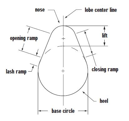
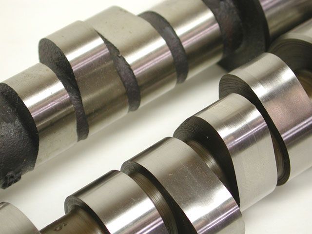
its NOT TYPICAL on the cheaper cams but its NOT hardly what you might call rare on cams that try to basically maximize results, and the current roller cam designs, because if you think about it the lobe is forced open as the roller rolls up and over the cam lobe but only spring pressure returns the valve most of the way to the cylinder head seat and they don,t want it to slam down and bounce so the lobe designs can be ground differently.An Asymmetrical cam has opening and closing ramps that are unlike and unequal. This profiles usually found on high performance cams and offers a high velocity opening and a lower velocity closing ramp in order to snap the valve open quickly and then set it back down more gently.
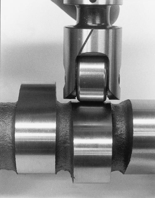
roller cam lobe designs are more complex than flat tapper cam lobes simply because the roller lifter allows much more precise valve open and timing events,
lobes on a roller cam,are generally asymmetrical, in the better roller cam lobe designs,
as its more important to open the valve fast, to maximize cylinder fill rates,
but reduce the valve seating/sealing, timing velocity, too prevent the valve bouncing off the seat as or after its closed,
this factor helps stabilize cylinder scavenging and valve train durability,
and stability but should not effect the software dyno results
Words and Photos by Wayne Scraba/ crane cams
3/8/04
What camshaft is right for your car? As you might have expected, there's some good news and there's also some bad news. Let's look at the bad stuff first. Given the overwhelming number of different engine combinations, vehicle setups, usage's and of course, camshaft grinds available, it is virtually impossible to make specific cam recommendations for each and every car, at least within the confines of this article (a book maybe). On the other hand, there's good news too. We've compiled some basic guidelines and generalities that can prove to be immensely helpful in the camshaft selection department.
Before we begin, think about this observation: In a basic high performance car, do you really need a flat tappet roller camshaft? Certainly it's tempting to emulate the Pros, but the overall costs associated with a high rpm, flat tappet roller camshaft valve train coupled with the maintenance program necessary to run such an arrangement might not be in equilibrium with grass roots motorsports. That isn't necessarily bad either. There are plenty of very stout hydraulic roller cams and solid lifter cams along with good old-fashioned hydraulic cams out there (and associated ancillary components). In fact, you might be pleasantly surprised at how much power a mild cam can produce. One more consideration is this: Take a look at the performances turned in by today's NHRA Stock Eliminator cars. Some combinations use hydraulic rollers (late model Camaros and Firebirds are a good example), and plenty more of those drag race stockers use a flat tappet of some sort (hydraulic or solid). And plenty of them run elapsed times deep into the ten-second zone. Granted, some Stock Eliminator racers use trick lifters that act more or less like solids, but many don't. Just as important, those cars are valve lift limited (which makes for some rather unusual grinds). Bracket cars and dual duty street-strip cars aren't.
Pressure Tactics ...
Even if you choose to go with a less exotic hydraulic cam, you still have to deal with the selection process. After deciding upon the camshaft type, the next item that you should consider in any engine package is cylinder pressure. While you may have never given this any thought, the camshaft is an integral component in the combustion process. In the heyday of the Detroit-built muscle car, compression ratios ranged between 10.5:1 and 12.5:1. A typical racecar can feature compression ratios in excess of 14:1 while many professional class drag cars (normally aspirated) feature static compression ratios in the area of 16:1. Generally speaking, a lower compression ratio street-style engine can easily use a camshaft that produces more cylinder pressure without fear of detonation. If this very same camshaft is installed in a powerplant with a high static compression ratio, the chances of experiencing severe detonation are increased manifold. In contrast, if a camshaft that is designed for use in a high static compression ratio engine is installed in a low C.R. "emission" or super low octane pump gas motor, the engine will simply roll over and die. Throttle response will be soggy and so will the power output.
Lifting The Valve ...
In the area of lift figures, the current trend seems to be leaning toward high and higher valve lift numbers. Of course, different engines "see" their own version of high lift, but generally speaking, most engines seem to respond toward high lift, short duration figures and wide lobe centers. This trend has been made possible with the advent of rapid valve event lobe profiles that have been developed within drag racing. Essentially, companies such as Crane have been able to design cam profiles that are capable of lifting a valve quicker than normal, lift the very same valve to a higher lift figure and then close it quickly without bouncing it off the seat. This form of cam design allows for more area under the curve and as a result, the cylinder is filled more efficiently with little or no trade-off in the overlap and duration departments. Recent valve spring technology has also contributed to this quick opening camshaft design. Just remember that valve spring life may be limited with such a camshaft package, but the short life cycle is generally attributed to specific category mechanical roller profiles. Today it's quite possible to build a hydraulic roller or flat tappet cam and make it live a long and healthy life with available valve spring technology.
Without question, a high lift camshaft also creates further changes in the engine. Piston-to-valve clearance should always be checked and double-checked any time a high lift cam is installed in an engine. High lift figures alone do not always contribute to piston-to-valve clearance problems. Overlap can also create more than its fair share of problems when discussing valve to piston clearance. A specific valve is seldom fully open when the piston reaches top dead center in a wide lobe center camshaft application. As the lobe center angle is decreased, the proximity of the valve face to the piston dome is increased. In a narrow lobe center, long overlap application; the valve remains open for a longer period of time as the piston approaches top dead center.
Smacking The Valve ...
In the preceding paragraphs we touched upon quick opening camshafts that set the valve down rapidly and then begin to taper off near the seat so that the valve does not bounce or hammer into the seat. In a nutshell, this is an asymmetrical cam design, another profile design that can easily be credited to drag race "thinkers". Try thinking of a camshaft lobe that is capable of hitting the lifter "hard" as it begins to open (this is an area where a flat tappet cam has an advantage over a roller -- it's not that easy to smack a roller with authority). The lifter will accelerate quickly in the bore (but it is held in check to some degree by the valve spring) until maximum lift is realized. The ideal situation includes the lifter accelerating quickly down the bore as well, but shortly before approaching the seat. This acceleration must be reduced so the valve does not hammer into the seat and begin to bounce uncontrollably. Although our imaginary camshaft is merely an exaggerated example, this is the essence of an asymmetrical cam profile -- one different shape for the valve opening and another for the valve closing.
When stepping up to a hydraulic roller, don't skimp on the valve springs.
Certainly the need for exotic springs (as found in some mechanical rollers) isn't required, but correct springs are.
The other type of cam profile is a symmetrical design. This configuration makes use of virtually identical opening and closing rates for the follower or lifter. So what is the big deal in a minor change in the opening and closing rates of a given lobe? Plenty! An asymmetrical cam design (with its different opening and closing rates) can actually increase available engine torque and can also contribute to a higher operating range. These are not massive gains (when compared to a symmetrical profile), however there are strong indications that most engines will respond favorably to contemporary asymmetrical configurations.
Single Or Dual Pattern?
In the area of single and dual pattern camshafts, controversy seems to reign supreme. Proponents of the dual pattern grind feel that a standard pushrod engine will breathe better on the intake side than it does on the exhaust side. In this scenario, the exhaust lift and duration figures are greater in order to compensate for the exhaust port inability to breathe. The single pattern group point out that the exhaust is somewhat controlled by the engine cylinder pressure. The piston movement helps to force the exhaust from the combustion chamber and as a result, the intake port does not have any real advantage. This makes for a single pattern camshaft that features identical intake and exhaust lobe profiles. Which is the better of the two designs? Both have merit. Your particular combination might respond properly with a dual pattern cam grind while another similar car might show promising results with a single pattern grind.
Getting It Right ...
Remember bigger is not always better when it comes to cams. Using a cam grind that a buddy uses in his vehicle might not be the correct cam for you. Finally, keep in mind that camshafts are not selected by price alone. An "off-the-shelf, on-sale" grind might have a reduced price sticker, but is it the right cam?
Ditto with small parts such as retainers, locks and seals. This stuff isn't expensive.
Buy it new and have it matched to the other valve train components. You won't be sorry.
With these three important factors in mind, your next step should be a consultation with your favorite camshaft manufacturer. Virtually all of the major cam companies offer a technical support department that is geared toward proper cam selection and installation. The tech line staff will ask a maze of questions when you make an inquiry. Be prepared to supply accurate information -- it's no use fudging on the details -- and the cam company will be able to match a specific cam to your vehicle. Also remember that with the variety of grinds available (coupled with the many variables found in your application), the cam company might have more than one cam to suit your particular application. As a result, it might be up to you to decide which cam is best suited to your vehicle. In some cases, you might even have to test two or more grinds to arrive at the sometimes "elusive" perfect cam combination.
So what can be expected by carefully tailoring the cam to the applications? How about significantly improved performance, better throttle response, more outright engine torque (and of course, improved horsepower), superior idle characteristics and yes, even more "tunability" in the engine? And by the way, you can get all of this with a relatively simple camshaft. Just remember to analyze your personal situation carefully and don't be afraid to contact a camshaft expert in regard to his or her opinion about camshafts in your application.
theres a great deal of useful info in the links and sub links below
viewtopic.php?f=52&t=90&p=114#p114
http://www.circletrack.com/techarticles ... index.html
viewtopic.php?f=52&t=90&p=114#p114
http://www.chevyhiperformance.com/techa ... index.html
viewtopic.php?f=52&t=324


")