READ THESE LINKS
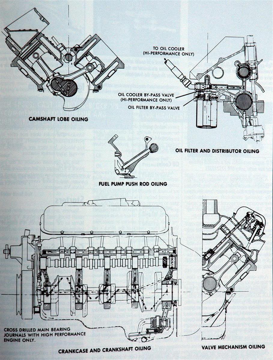
in a properly set up block a pressurized oil film supports the cam and main bearings, pressurized oil flows from the oil passages in the block to the main bearings where its routed through feed channels to rod bearings, the rotating crank helps to feed cooling oil to the bearings and the oil flow thrown from the rod side clearance helps cool and lube the rings and cam lobes
while it is surely going to take some time and effort to read all the links and sub-links provided , I think youll find its well worth that time spent in that it will save you a great deal of money and wasted effort to know exactly what youll benefit from and what to avoid
http://garage.grumpysperformance.com/index.php?threads/oil-system-mods-that-help.2187/
http://garage.grumpysperformance.co...ed-holes-in-bearings-shells.10750/#post-64733
http://garage.grumpysperformance.co...connecting-rods-pistons.247/page-2#post-57772
http://garage.grumpysperformance.com/index.php?threads/bearing-clearances.2726/#post-56090
http://garage.grumpysperformance.com/index.php?threads/tweaking-a-350-383.13087/#post-68201
http://garage.grumpysperformance.co...a-1970-era-bbc-engine-build.13073/#post-68082
http://www.howcast.com/videos/178592-Cr ... Chamfering
http://www.hotrod.com/howto/7234_cranks ... index.html
viewtopic.php?f=53&t=2728&p=9886&hilit=grinder#p9886
http://www.circletrack.com/tipstricks/4 ... index.html
viewtopic.php?f=27&t=1831&p=9240&hilit=+grinder#p9240
viewtopic.php?f=53&t=204
http://www.chevyhiperformance.com/tech/ ... index.html
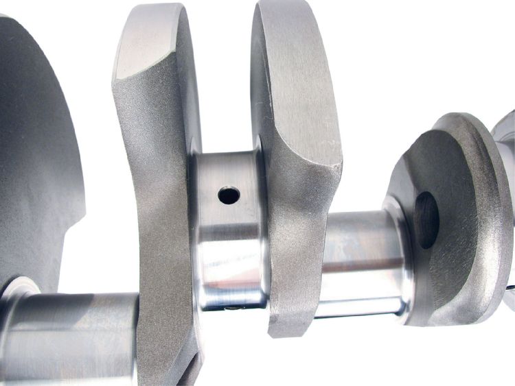
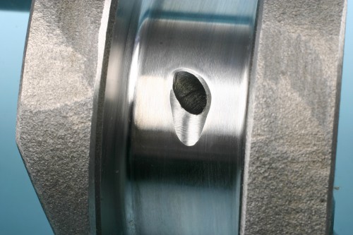
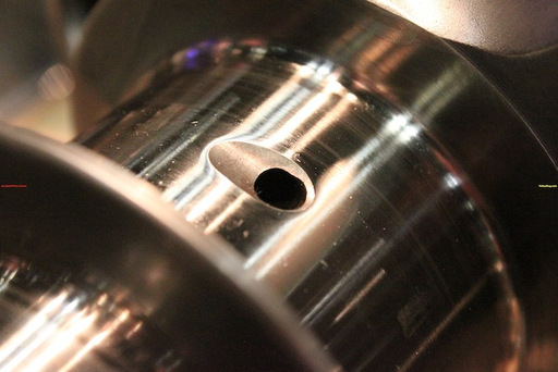
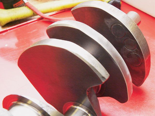
NON-CHAMFERED oil holes
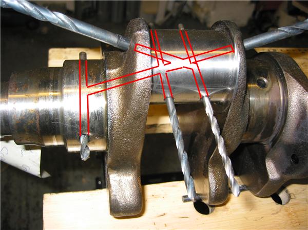
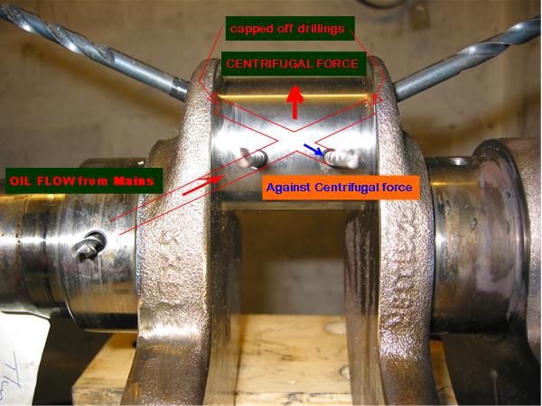
tear dropping or chamfering the edge of the oil feed passage holes in the crank journals reduces the SHEARING of the oil flow as it exits the oil passage's and that extra oil flow that results, helps to cool and support the crank journal , and connecting rod bearings and prevents the bearing from contacting the crank or connecting rods as a cushioning oil film separates the moving surface of the journal from the bearing inserts

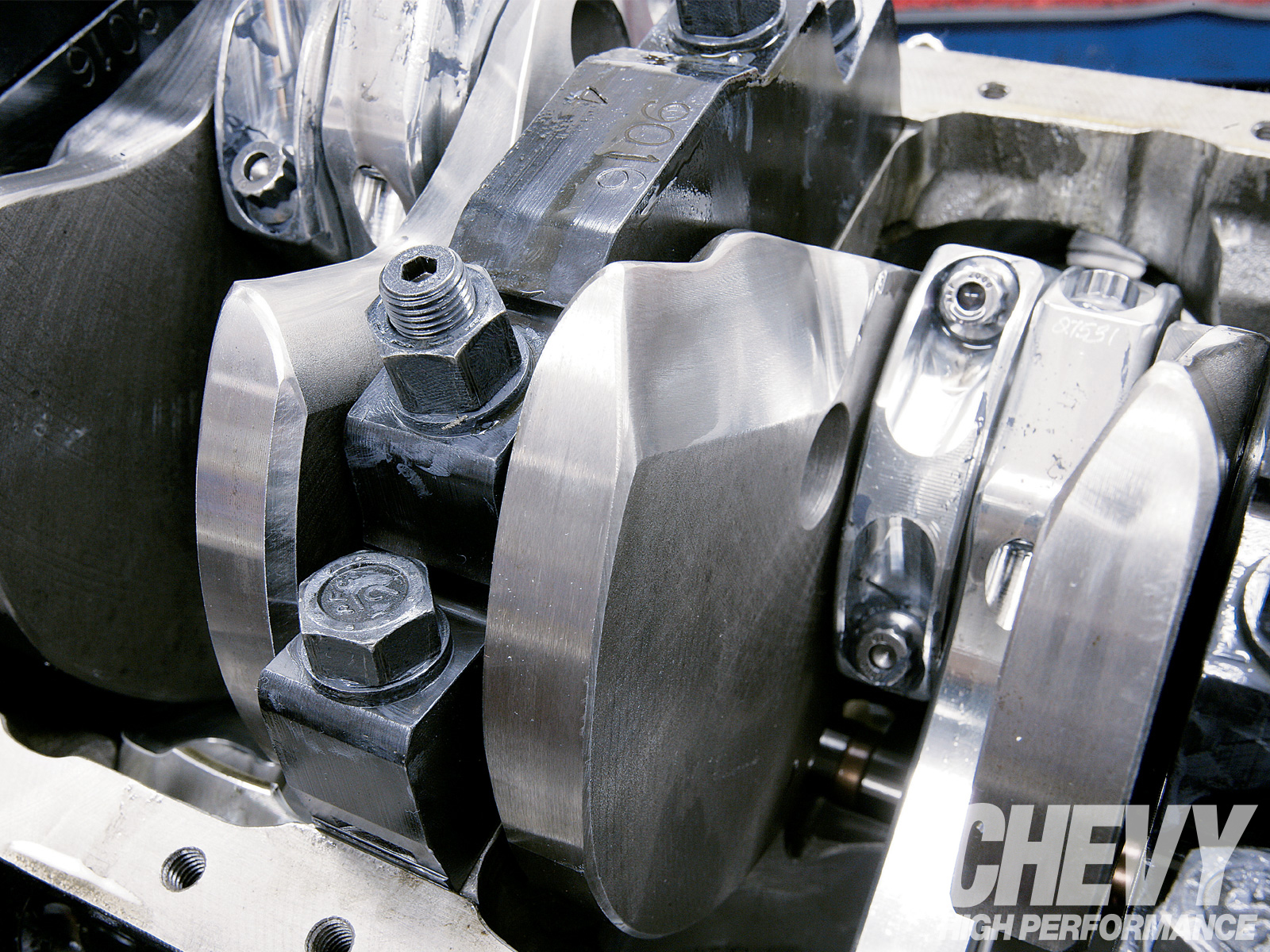
I've placed both scat and eagle crank shafts next to a similar chevy OEM crank, and carefully examined all three and in my opinion the eagle crank was the least well finished with the scat crank being the best, now obviously all three manufacturers have made several grades of cranks and Ive used a truck load of SCAT and FORGED CHEVY crank shafts over the years with good results
viewtopic.php?f=54&t=64&p=77#p77
knife edging a cranks counter weights BEFORE balancing the assembly reduces windage looses but can also make balancing the assembly more expensive
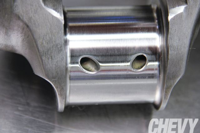
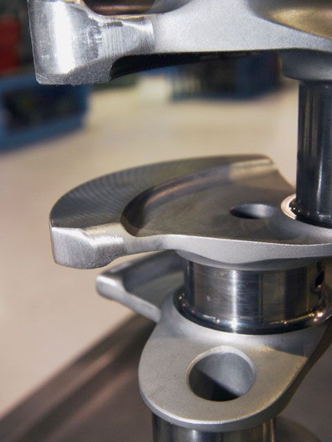
just keep in mind that you'll need to very carefully blend and smooth and carefully clean,the edges of the beveled area where the oil port feeds the bearing surface with some 600 grit sand paper so the oil flows well and theres no edges to cause bearing wear issues or crud left from the process that would get embedded in the bearings.
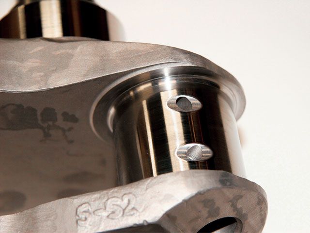
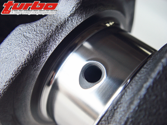
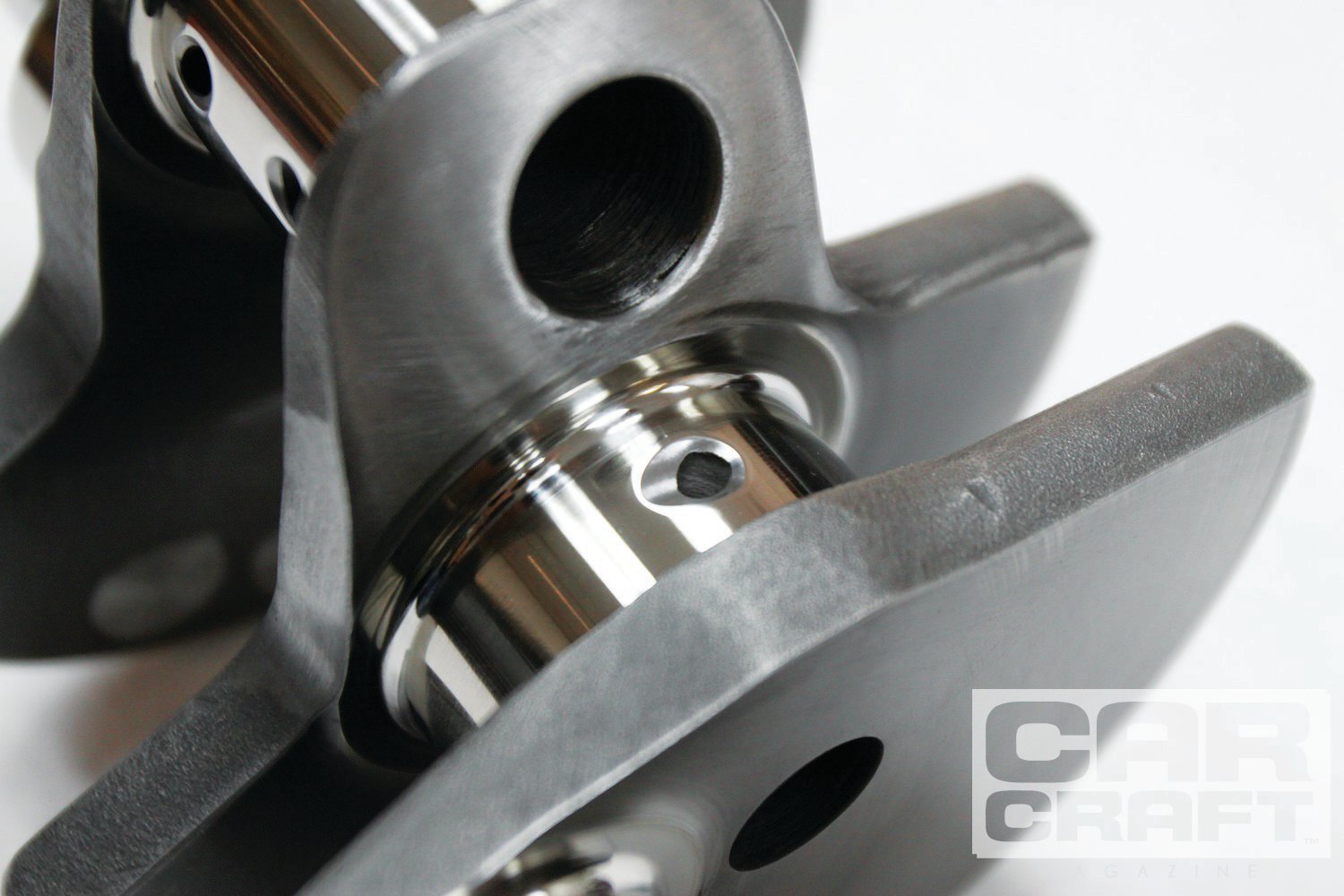
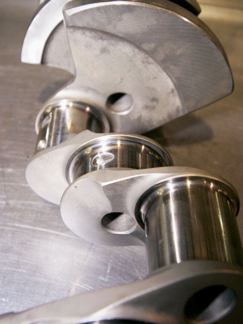
CHAMFERED oil holes
Which Crankshaft Meets Your Racing Needs Best?
By Larry Carley
There are a lot of racing crankshafts in the automotive aftermarket today. You’ll find a wide variety of styles, strokes, weights and price ranges from which you can choose.
The question you need to be asking is which crank is “right†for the engine you’re building? The answer to that question depends on several things – and it may be different in almost every situation.
First, what are your limitations? Are you constrained by price? Can you afford to spend upwards of $3,000 on a top-of-the-line racing crank, or are you limited to spending $800 or less on a budget crank? Is the displacement of the engine restricted by class rules, or is the sky the limit? How much stroke can the block you’re building reasonably handle? What will be the maximum rpm of the engine? Will the engine run on pump gas, racing fuel, alcohol or nitrous? Will it be naturally aspirated, turbocharged or supercharged?
Once you’ve nailed down the basic limitations on the engine you’re building, you can start thinking about things like how much power you want to make and where you want the torque curve to be. Do you want to build a high revving engine that makes gobs of power from 5,500 rpm and up, or do you want to build a grunt motor that makes lots of torque and pulls strong from low rpm through mid-range? The answers to these questions will determine not only what kind of crankshaft you ultimately choose, but the connecting rods, pistons, cylinder heads, intake and exhaust manifolds, fuel delivery system, camshaft and valvetrain that will work best with that crank as well.
Bore And Stroke
The bore and stroke of the engine in effect become the starting point for planning and building a performance engine. Bore dimensions will be limited either by class rules or the physical limits of the engine block. So if you want more cubic inches than the stock bore and stroke provide, you have to overbore the cylinders and/or stroke the crankshaft.
The stroke of a crankshaft can be increased in a variety of ways. One is to offset grind the journals of a stock crank to a smaller diameter to increase the stroke. Another is to weld up the thickness of the rod journals and remachine the journals back to their original size or undersize with more offset. Or replace the stock crank with a forged or billet stroker crank.
On an LS1 Chevy smallblock V8 with stock bores of 3.8976" (99 mm), increasing the stroke from the stock 3.622" (92 mm) to 4.000" (101.6 mm) will increase displacement from the stock 346 cubic inches to 382 cubic inches – a 10 percent increase. Go to a 4.250" crank, and you bump up the displacement to 406 cubic inches – a 17 percent increase.
The increase in displacement roughly translates into an equal increase in power and torque even if no additional modifications are made to the engine. Of course, to make the most of the extra cubic inches, valve opening, lift and duration can all be increased a similar amount to make the most power.
There’s no substitute for cubic inches when it comes to making power. The larger the engine’s displacement, the more air and fuel it can suck through its cylinders. Maximum airflow in a naturally aspirated engine is limited by rpm, the size of the valves, valve lift and duration, the port volume of the cylinder heads, restrictions in the intake and exhaust systems, and the area of the throttle body or bodies.
Increasing the stroke of the crankshaft increases displacement by making the pistons travel further down the cylinders. This increases the “swept volume†of the cylinders and pulls more air into the engine. The increase in airflow also increases air velocity through the heads, which means a stroked engine can handle somewhat larger ports and valves for more top end power, too. Increasing stroke also increases compression because the piston is now traveling a longer distance and compressing a larger volume of air and fuel into the same space as before. Increasing stroke has less effect on compression, though, than increasing the size of the bores – and less effect on increasing the risk of detonation.
Why? Because increasing stroke also increases piston speed and causes the piston to spend less time at top dead center on the compression stroke. That means the hot expanding gases that have just been ignited can start pushing the piston down sooner. This reduces peak combustion pressures somewhat, and lessens the risk of engine-damaging detonation and preignition. But increasing stroke also increases piston speeds when the pistons reach the half-way point in the cylinders which increases friction, ring and cylinder wear.
Short stroke engines, by comparison, cause the piston to linger longer at top dead center. This allows compression pressures to build to a higher level before the piston starts to move down, essentially giving a little more bang early in the power stroke. But the trade-off is an increased risk of detonation on pump gas especially if the compression ratio is much higher than 9:1.
The main advantage of increasing stroke, however, is its effect on torque. Increasing the stroke lengthens the throw or the “moment arm†of the crankshaft. In effect, this creates more leverage as the piston pushes down on the crank. It’s the same as using a longer pedal crank on a bicycle or a handle extension on a breaker bar.
Torque equals the force exerted on the crank times the length of the crank stroke. Torque is what you want because torque is what does the work and pushes the race car down the track.
Horsepower, on the other hand, is the rate at which torque is applied. One horsepower is equal to 33,000 ft.lbs. of torque per minute, or 550 ft.lbs. per second.
Torque and horsepower both increase with rpm up to a point, and then start to fall off as engine speed starts to surpass the engine’s ability to breathe efficiently. When plotted on a graph, the torque and horsepower curves create a pair of intersecting humps that define the engine’s overall performance characteristics. The torque curve usually starts out much higher than the horsepower curve, but peaks out at a lower rpm and a lower maximum value than the horsepower curve. Ideally, you want a relatively flat torque curve so the engine will pull strong throughout its rpm range. That’s relatively easy to do with a large displacement stroker motor, but is much harder to accomplish with a small turbocharged engine that has little power or torque until the turbo boost kicks in.
Here’s another weird science fact: Horsepower multiplied by engine rpm divided by 5252 equals torque.
So? This means that at 5252 rpm, the engine’s torque curve and horsepower curve cross each other, and torque and horsepower are the same at that point. Below 5252 rpm, torque makes less horsepower than above 5252 rpm. Consequently, if you build a long stroke engine to make lots of low end torque, it may not produce as much total horsepower at higher rpms as an engine with the same displacement but a shorter stroke.
An example of how this applies to actual racing is found in a NASCAR engine. Rules limit the engine’s total displacement to a maximum of 358 cubic inches. These engines typically rev as high as 9,800 rpm and produce upwards of 750 horsepower. The power curve typically peaks from 4,500 rpm to 8,000 rpm, depending on how the engine is set up for the race. NASCAR teams typically change engines between races, and use a different bore and stroke depending on the track. A longer stroke provides more low end torque on a short track where acceleration out of the turns is more important than maximum speed. A shorter stroke, larger bore engine, on the other hand, is usually the choice on a superspeedway where top speed wins races.
Crank Materials
Most stock cranks and even some street performance cranks are made of cast iron and steel alloys. A 1053 high-carbon alloy steel typically has around 100,000 psi tensile strength. This is adequate for a stock or even mild performance engine, but is not strong enough to withstand the rigors of serious racing. Stock cast cranks can safely handle up to 350 horsepower in a small block V8, or up to 400 horsepower in a big block V8 with a redline of 5,000 to 5,500 rpm. Beyond these limits, a better grade of material is needed.
A forged crankshaft made of 5140 grade steel alloy is a good upgrade and has around 115,000 psi tensile strength. A 5140 alloy contains less carbon (0.38 to 0.43 percent) than 1053 alloy (0.47 to 0.55 percent), plus it has chrome (0.9 to 1.7 percent) and silicon (0.2 to 0.35 percent) to improve durability. The difference in carbon between 1053 and 5140 is not as important as the chrome, which add strength and toughness. With the proper heat treating, a 5140 forged crank is an economical choice for many Sportsman class racers or the street/strip Saturday night racer.
If you’re building a small block V8 that’s capable of making more than 450 horsepower, a big block that’s making upwards of 550 horsepower or you’re pushing the engine’s redline beyond 7,000 rpm, you should upgrade to a performance crank – which usually means a forged or billet 4340 steel crank. Forged cranks made of 4340 alloy typically have a tensile strength of 140,000 to 145,000 psi and are much more resistant to fatigue than 5140 or 1053. A forged 4340 billet crank will typically have a fatigue strength of 160,000 to 165,000 psi. The increased strength is due to the addition of nickel (1.65 to 2.0 percent) and molybdenum (0.2 to 0.3 percent).
Something else to keep in mind is that not all “4340†alloys are the same. ASM (American Society for Metals) grading standards allow a certain range for the amount of each element in the steel. If the concentration of a particular element such as chrome, nickel or molybdenum is at the upper or lower limit, it can affect the ultimate strength of the alloy. Also, we’ve heard reports that some 4340 alloys from offshore suppliers don’t necessarily conform to ASM standards. Some contain contaminants that have an adverse effect on strength and other properties. That’s one reason why some offshore forgings are priced much less than their domestic counterparts. The alloys are not the same.
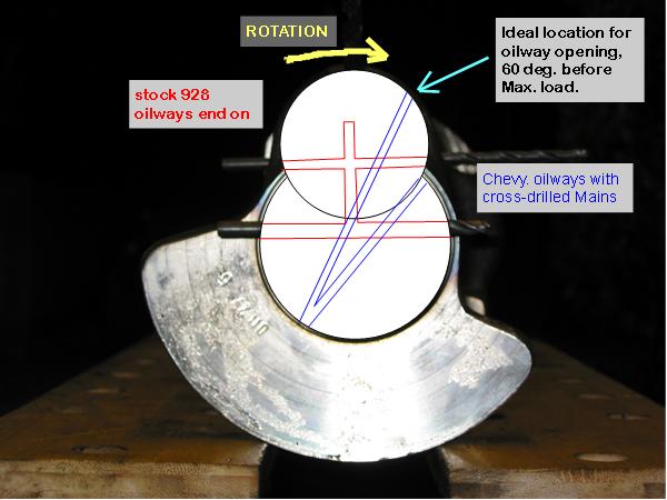
Most crankshaft failures occur as a result of bending fatigue rather than torsional twisting. In other words, the crankshaft is strong enough to handle the loads, but the vibrations and flexing that occur at high rpm and loads beat it to death. Cracks typically develop in the journal fillets, which is why most racing cranks are machined with a larger radius in the fillets (which requires chamfered bearings), and stress relieved by shot peening. Cracks can also radiate from the oil holes in the journals. Chamfering the oil holes not only helps spread the oil but also relieve stress in this critical area. Cracks may also occur in the crank nose or number one main journal when nose loads are unusually high (blower drives), or the harmonic damper is loose or out of balance.
Engine speed is also a critical factor in crankshaft loading. The loads on the crank go up exponentially with rpm. With a longer crank, the loads are higher so extra strength is needed if the engine is to survive at higher rpms.
The strength of the crank not only depends on the base alloy, therefore, but also on how it was made (whether it was drop-forged or machined from solid chunk of billet steel). A welded up stroker crank may be okay for a street engine but probably isn’t strong enough for racing.
Forgings generally produce a flowed grain structure, which is stronger than a casting. Even so, the forging process stretches, pulls and deforms the grain structure, and subsequent machining cuts through the grain structure. The strength of the forging also depends on the metallurgy of the alloy used, and the heat treatment that is applied to it after it has been shaped. Forgings require a die to shape the metal. Dies and forging presses are expensive (which adds to the cost of the crankshaft), so the availability of forgings for various applications depends on their popularity and how much people are willing to pay for a forged crank.
Billet crankshafts, by comparison, are CNC machined from a solid chunk of forged steel. The grain structure is not stretched or deformed, and machining leaves fewer residual stresses in the metal. Consequently, some crank manufacturers say billet cranks are the strongest cranks available. Most Top Fuel drag racers run billet cranks, as do many circle track racers. Another advantage with billet cranks is that CNC machining allows a crank to be custom made with virtually any stroke, journal diameter, configuration or countershaft placement that will fit the engine. A billet crank can be one-of-a-kind or mass produced.
Durability
A performance crank has to be tough to survive the rigors of racing. Tough means strong and capable of withstanding torsional loads as well as bending and flexing without cracking.
Durability depends on the material the crank is made from, the method used to make the crank (forged or billet), the size of the rod journals, and the radius of the journal fillets. Bigger journals are stronger, but many racers want smaller journals to reduce friction. Consequently, the crank itself must be stronger.
Most racing cranks are heat treated and case hardened to provide additional strength and durability. The journal surfaces may be hard chromed, nitrided or induction hardened. Nitriding is often used, and can be done by several methods. Some crank manufacturers use a “plasma nitriding†process that vacuum-deposits ionized nitrogen on the surface of the crank inside a high temperature oven. Others use a process called Tufftriding that soaks the crank in a hot “ferric nitrocarburizing†salt bath, or heats the crank to 950 degree F in an oven filled with nitrogen. Nitrogen penetrates the surface of the metal and changes the microstructure of the steel. This roughly doubles the hardness of the surface from about 30 to 35 Rockwell C to 60 Rockwell C, and increases fatigue life up to 25 percent or more.
Aerodynamics, Cryogenics and Coatings
Racing cranks typically have counterweights that are shaped to cut wind resistance and drag as the crank spins in the crankcase. Drag slows the crank at high speed and robs power that could otherwise go to the wheels. Special non-stick coatings may also be used on the counterweights so the crank will shed oil more easily. This also helps reduce drag, windage and allows the oil to return to the oil pan or sump more quickly.
The journals are usually not coated, but are micro-polished to a mirror finish. Micro-polishing can take the surface finish down to 2 or 3 RA, which may be needed if you’re running close bearing clearances for a low viscosity synthetic oil.
Some racing cranks are also cryogenically treated by freezing them in a tank at several hundred degrees below zero to relax and improve the grain structure of the steel. Those who treat their cranks this way swear it makes them virtually bullet-proof.
Machining And Weight Considerations
Performance cranks are also finished to a much higher standard of accuracy and precision than ordinary cranks. The indexing of the journals and the location and roundness of the journals is carefully controlled to provide exact dimensions.
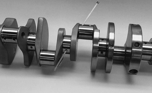
The weight of the crank can be reduced by machining away “unnecessary†metal. This may include reducing the size of the counterweights and drilling out the throws. A lightened crank with cut down counterweights and drilled throws may weigh as much as 20 lbs. less than a stock crank. Most crank supplies say the trend to lighter and lighter racing cranks in recent years may have bottomed out because most of the weight that can be safely taken out has already been removed and there’s not much room left for further reductions.
The theory here is that reducing the weight of the crankshaft reduces weight and inertia, allowing the engine to rev more quickly. But the ability to do this depends on the location of the weight with respect to the center axis of the crankshaft. Weight that is closer in to the center of the axis of rotation has much less effect on inertia than weight located out on the crank pins or counterweights. A super light crank makes sense in an application like a sprint car on a short dirt track where the driver is constantly on and off the throttle in the corners. But in a drag motor or a NASCAR motor that runs at full throttle, inertia is much less important than durability. Because of this, many crank suppliers recommend running a heavier crank that has added stiffness and strength in a drag motor or NASCAR motor to keep the bottom end of the motor intact.
A crankshaft that’s too light can also flex and lose horsepower – or fail – which is something to keep in mind, too. Something else to consider is balancing: stroker cranks often require the addition of heavy metal plugs to the counterweights. This adds to the cost of the crank.
Finally, racing cranks need a good harmonic balancer. The balancer helps dampen torsional vibrations that may cause a crankshaft to fail or the nose to crack. One crankshaft manufacturer recommends using the lightest and smallest diameter dampener, and balancing the crankshaft with the damper bolted in place. Not balancing the crank with the dampener in place, it is reported, is like trying to balance a wheel with a flat tire.
For racing applications, the same crank manufacturer also recommends using a dampener with an elastomer ring rather than a fluid filled dampener or one with moving parts. They say engine speed changes too quickly in a racing engine for dampeners that are “self-balancing.†A conventional elastomer dampener, in their opinion, eliminates any chance of cold start vibrations and reduces the risk of nose failure on the crankshaft.
Engine Bearing Installation and Fitting Tips
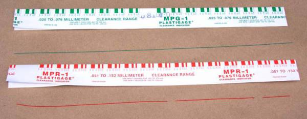
When measuring bearing measurements, they should always be taken at 90-degrees to the parting line to determine the minimum clearance. If measuring the bearing wall thickness, use a special micrometer with a ball anvil to fit the curvature of the bearing ID. The best way to determine bearing clearance is to measure the bearing ID with the bearings installed in the housing and the bolts torqued to the specified assembly torque. Use a dial bore gauge to measure the bearing ID at 90-degrees to the parting line, then subtract shaft size from bearing ID to determine the clearance. If the dial bore gauge is zeroed at the actual diameter of the crankshaft journal to be installed, the dial bore gauge will then read clearance directly and the subtraction calculation can be eliminated. About .001" clearance per inch of shaft diameter is a good rule of thumb. Increasing that by about .0005" will add a little margin of safety when starting out, especially for rods. Example: .001" X 2.100 = .0021" then add .0005", so starting out set clearance at .0026" for a 2.100 shaft.
If clearance adjustments need to be made, use either an extra clearance part for more clearance or an undersize part for less clearance. It is permissible to mix sizes if less than .001" adjustment in clearance is desired. When mixing sizes for a select fitting: a) never mix parts having more than .0005" difference in wall size; b) and always install the thickest wall shell in the upper position if installing a rod bearing or the lower position if installing a main bearing. When working with a reground shaft, always measure assembled bearing ID's first. Next have a shaft sized to produce the desired clearance since there are no extra clearance parts available for undersize shafts.
When measuring a bearing ID or wall thickness, avoid measuring at the parting line. The diagram illustrates there is a parting line relief machined into nearly all bearing shells. This relief is to allow for any mis-match between upper and lower shells due to tolerance differences, or possibly resulting from cap shift or twist during assembly. To determine bearing wall eccentricity or assembled bearing ID ovality, measure at a point at least 3/8" away from the parting line.
When installing any bearing DO NOT ATTEMPT TO POLISH THE BEARING RUNNING SURFACE WITH ANY TYPE OF ABRASIVE PAD OR PAPER. Bearing overlay layers are extremely soft and thin – typically .0005" on high performance parts. These thin layers can easily be damaged or removed by an abrasive media. Because the overlay layer is electroplated, it may exhibit microscopic plating nodules that make it feel slightly rough. The nodules are the same material as the rest of the plated layer and will quickly be flattened by the shaft. Bearing surfaces can be lightly burnished with solvent and a paper towel if desired.
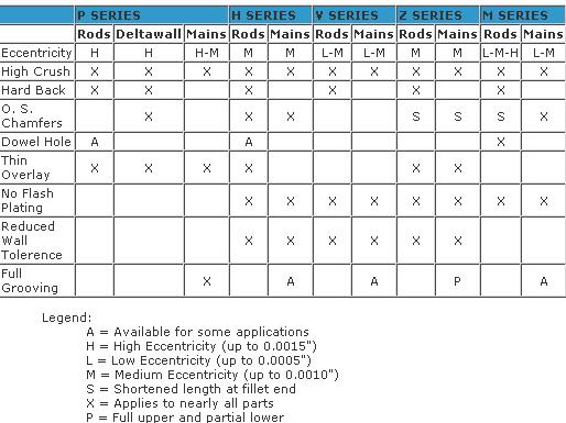
Arriving at the correct choice of a high performance bearing for any given racing application is much like determining what clearance works best. From past experience, our knowledge of the intended usage and common sense can guide us in making an initial choice. Next, we can fine tune the selection process based on those results. The information given here is intended to aid in the initial selection as well as the fine tuning process.
The following table serves as a brief overview of the features included in each of the special Clevite 77® brand high performance bearing series.
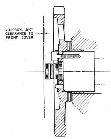
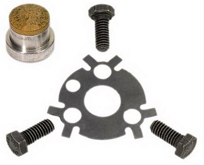
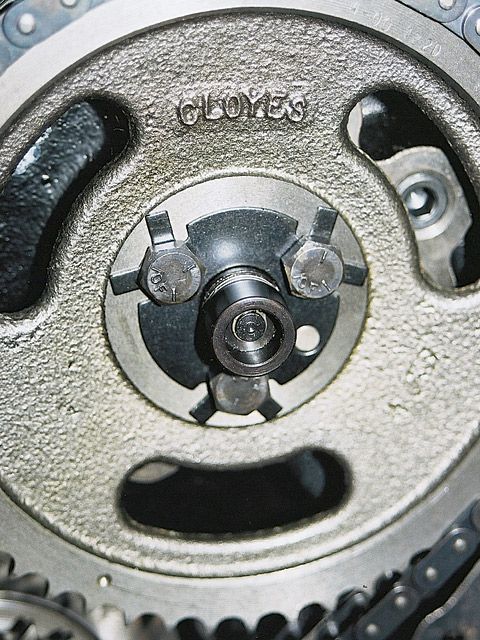
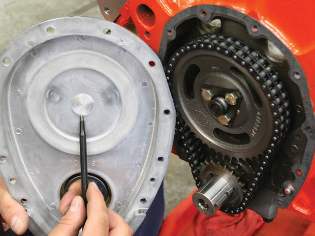
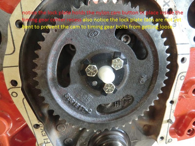
this cam buttons correctly installed but the retainer plate tabs have not been bent up to lock the bolt heads from rotating


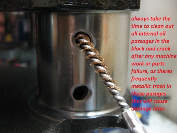
fine (micro) debris circulating in the oil, can rapidly cause damage in any engine, use of magnets helps reduce this but a proper pressure cleaning of the block with all oil passage plugs and bearings previously removed and a rifle bore brush run through all oil passages is ALWAYS mandatory on a used or even new engine block.
(common if the oil passages in the block are not properly cleaned after engine bearing failure)
and less than quality crank journal polishing
read the links it should help
http://garage.grumpysperformance.com/index.php?threads/types-of-crankshaft-steel.204/#post-239
http://garage.grumpysperformance.com/index.php?threads/can-i-get-it-polished.9214/#post-33116
http://garage.grumpysperformance.co...shaft-journal-surface-finnish.2728/#post-9886
http://garage.grumpysperformance.com/index.php?threads/thrust-bearing-wear.619/#post-37676
http://garage.grumpysperformance.co...uring-crank-bearing-journals.5478/#post-16429
http://garage.grumpysperformance.co...ing-oil-feed-holes-in-cranks.4419/#post-11637
http://garage.grumpysperformance.co...ank-durring-short-blk-assembly.852/#post-1311
http://garage.grumpysperformance.com/index.php?threads/analyzing-piston-damage.16432/
http://garage.grumpysperformance.co...pes-of-crankshaft-steel.204/page-2#post-46231
these books should help
http://www.themotorbookstore.com/engine ... nting.html
http://www.rehermorrison.com/rmEngineBook.htm
in a properly set up block a pressurized oil film supports the cam and main bearings, pressurized oil flows from the oil passages in the block to the main bearings where its routed through feed channels to rod bearings, the rotating crank helps to feed cooling oil to the bearings and the oil flow thrown from the rod side clearance helps cool and lube the rings and cam lobes
while it is surely going to take some time and effort to read all the links and sub-links provided , I think youll find its well worth that time spent in that it will save you a great deal of money and wasted effort to know exactly what youll benefit from and what to avoid
http://garage.grumpysperformance.com/index.php?threads/oil-system-mods-that-help.2187/
http://garage.grumpysperformance.co...ed-holes-in-bearings-shells.10750/#post-64733
http://garage.grumpysperformance.co...connecting-rods-pistons.247/page-2#post-57772
http://garage.grumpysperformance.com/index.php?threads/bearing-clearances.2726/#post-56090
http://garage.grumpysperformance.com/index.php?threads/tweaking-a-350-383.13087/#post-68201
http://garage.grumpysperformance.co...a-1970-era-bbc-engine-build.13073/#post-68082
http://www.howcast.com/videos/178592-Cr ... Chamfering
http://www.hotrod.com/howto/7234_cranks ... index.html
viewtopic.php?f=53&t=2728&p=9886&hilit=grinder#p9886
http://www.circletrack.com/tipstricks/4 ... index.html
viewtopic.php?f=27&t=1831&p=9240&hilit=+grinder#p9240
viewtopic.php?f=53&t=204
http://www.chevyhiperformance.com/tech/ ... index.html
NON-CHAMFERED oil holes
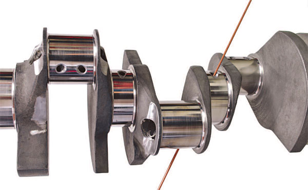
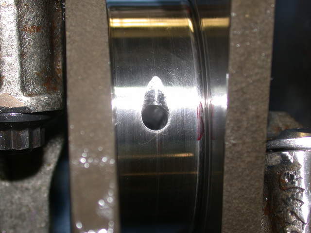
tear dropping or chamfering the edge of the oil feed passage holes in the crank journals reduces the SHEARING of the oil flow as it exits the oil passage's and that extra oil flow that results, helps to cool and support the crank journal , and connecting rod bearings and prevents the bearing from contacting the crank or connecting rods as a cushioning oil film separates the moving surface of the journal from the bearing inserts
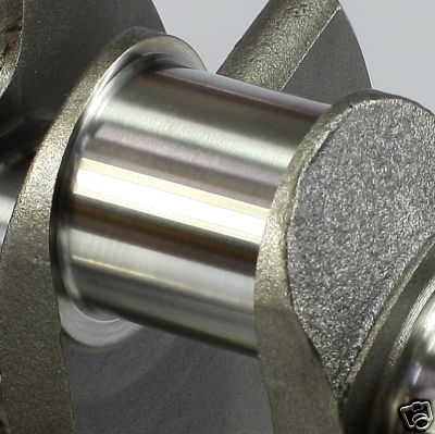
I've placed both scat and eagle crank shafts next to a similar chevy OEM crank, and carefully examined all three and in my opinion the eagle crank was the least well finished with the scat crank being the best, now obviously all three manufacturers have made several grades of cranks and Ive used a truck load of SCAT and FORGED CHEVY crank shafts over the years with good results
viewtopic.php?f=54&t=64&p=77#p77
knife edging a cranks counter weights BEFORE balancing the assembly reduces windage looses but can also make balancing the assembly more expensive
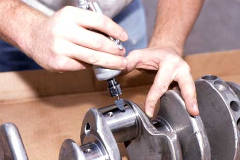
just keep in mind that you'll need to very carefully blend and smooth and carefully clean,the edges of the beveled area where the oil port feeds the bearing surface with some 600 grit sand paper so the oil flows well and theres no edges to cause bearing wear issues or crud left from the process that would get embedded in the bearings.
CHAMFERED oil holes
Which Crankshaft Meets Your Racing Needs Best?
By Larry Carley
There are a lot of racing crankshafts in the automotive aftermarket today. You’ll find a wide variety of styles, strokes, weights and price ranges from which you can choose.
The question you need to be asking is which crank is “right†for the engine you’re building? The answer to that question depends on several things – and it may be different in almost every situation.
First, what are your limitations? Are you constrained by price? Can you afford to spend upwards of $3,000 on a top-of-the-line racing crank, or are you limited to spending $800 or less on a budget crank? Is the displacement of the engine restricted by class rules, or is the sky the limit? How much stroke can the block you’re building reasonably handle? What will be the maximum rpm of the engine? Will the engine run on pump gas, racing fuel, alcohol or nitrous? Will it be naturally aspirated, turbocharged or supercharged?
Once you’ve nailed down the basic limitations on the engine you’re building, you can start thinking about things like how much power you want to make and where you want the torque curve to be. Do you want to build a high revving engine that makes gobs of power from 5,500 rpm and up, or do you want to build a grunt motor that makes lots of torque and pulls strong from low rpm through mid-range? The answers to these questions will determine not only what kind of crankshaft you ultimately choose, but the connecting rods, pistons, cylinder heads, intake and exhaust manifolds, fuel delivery system, camshaft and valvetrain that will work best with that crank as well.
Bore And Stroke
The bore and stroke of the engine in effect become the starting point for planning and building a performance engine. Bore dimensions will be limited either by class rules or the physical limits of the engine block. So if you want more cubic inches than the stock bore and stroke provide, you have to overbore the cylinders and/or stroke the crankshaft.
The stroke of a crankshaft can be increased in a variety of ways. One is to offset grind the journals of a stock crank to a smaller diameter to increase the stroke. Another is to weld up the thickness of the rod journals and remachine the journals back to their original size or undersize with more offset. Or replace the stock crank with a forged or billet stroker crank.
On an LS1 Chevy smallblock V8 with stock bores of 3.8976" (99 mm), increasing the stroke from the stock 3.622" (92 mm) to 4.000" (101.6 mm) will increase displacement from the stock 346 cubic inches to 382 cubic inches – a 10 percent increase. Go to a 4.250" crank, and you bump up the displacement to 406 cubic inches – a 17 percent increase.
The increase in displacement roughly translates into an equal increase in power and torque even if no additional modifications are made to the engine. Of course, to make the most of the extra cubic inches, valve opening, lift and duration can all be increased a similar amount to make the most power.
There’s no substitute for cubic inches when it comes to making power. The larger the engine’s displacement, the more air and fuel it can suck through its cylinders. Maximum airflow in a naturally aspirated engine is limited by rpm, the size of the valves, valve lift and duration, the port volume of the cylinder heads, restrictions in the intake and exhaust systems, and the area of the throttle body or bodies.
Increasing the stroke of the crankshaft increases displacement by making the pistons travel further down the cylinders. This increases the “swept volume†of the cylinders and pulls more air into the engine. The increase in airflow also increases air velocity through the heads, which means a stroked engine can handle somewhat larger ports and valves for more top end power, too. Increasing stroke also increases compression because the piston is now traveling a longer distance and compressing a larger volume of air and fuel into the same space as before. Increasing stroke has less effect on compression, though, than increasing the size of the bores – and less effect on increasing the risk of detonation.
Why? Because increasing stroke also increases piston speed and causes the piston to spend less time at top dead center on the compression stroke. That means the hot expanding gases that have just been ignited can start pushing the piston down sooner. This reduces peak combustion pressures somewhat, and lessens the risk of engine-damaging detonation and preignition. But increasing stroke also increases piston speeds when the pistons reach the half-way point in the cylinders which increases friction, ring and cylinder wear.
Short stroke engines, by comparison, cause the piston to linger longer at top dead center. This allows compression pressures to build to a higher level before the piston starts to move down, essentially giving a little more bang early in the power stroke. But the trade-off is an increased risk of detonation on pump gas especially if the compression ratio is much higher than 9:1.
The main advantage of increasing stroke, however, is its effect on torque. Increasing the stroke lengthens the throw or the “moment arm†of the crankshaft. In effect, this creates more leverage as the piston pushes down on the crank. It’s the same as using a longer pedal crank on a bicycle or a handle extension on a breaker bar.
Torque equals the force exerted on the crank times the length of the crank stroke. Torque is what you want because torque is what does the work and pushes the race car down the track.
Horsepower, on the other hand, is the rate at which torque is applied. One horsepower is equal to 33,000 ft.lbs. of torque per minute, or 550 ft.lbs. per second.
Torque and horsepower both increase with rpm up to a point, and then start to fall off as engine speed starts to surpass the engine’s ability to breathe efficiently. When plotted on a graph, the torque and horsepower curves create a pair of intersecting humps that define the engine’s overall performance characteristics. The torque curve usually starts out much higher than the horsepower curve, but peaks out at a lower rpm and a lower maximum value than the horsepower curve. Ideally, you want a relatively flat torque curve so the engine will pull strong throughout its rpm range. That’s relatively easy to do with a large displacement stroker motor, but is much harder to accomplish with a small turbocharged engine that has little power or torque until the turbo boost kicks in.
Here’s another weird science fact: Horsepower multiplied by engine rpm divided by 5252 equals torque.
So? This means that at 5252 rpm, the engine’s torque curve and horsepower curve cross each other, and torque and horsepower are the same at that point. Below 5252 rpm, torque makes less horsepower than above 5252 rpm. Consequently, if you build a long stroke engine to make lots of low end torque, it may not produce as much total horsepower at higher rpms as an engine with the same displacement but a shorter stroke.
An example of how this applies to actual racing is found in a NASCAR engine. Rules limit the engine’s total displacement to a maximum of 358 cubic inches. These engines typically rev as high as 9,800 rpm and produce upwards of 750 horsepower. The power curve typically peaks from 4,500 rpm to 8,000 rpm, depending on how the engine is set up for the race. NASCAR teams typically change engines between races, and use a different bore and stroke depending on the track. A longer stroke provides more low end torque on a short track where acceleration out of the turns is more important than maximum speed. A shorter stroke, larger bore engine, on the other hand, is usually the choice on a superspeedway where top speed wins races.
Crank Materials
Most stock cranks and even some street performance cranks are made of cast iron and steel alloys. A 1053 high-carbon alloy steel typically has around 100,000 psi tensile strength. This is adequate for a stock or even mild performance engine, but is not strong enough to withstand the rigors of serious racing. Stock cast cranks can safely handle up to 350 horsepower in a small block V8, or up to 400 horsepower in a big block V8 with a redline of 5,000 to 5,500 rpm. Beyond these limits, a better grade of material is needed.
A forged crankshaft made of 5140 grade steel alloy is a good upgrade and has around 115,000 psi tensile strength. A 5140 alloy contains less carbon (0.38 to 0.43 percent) than 1053 alloy (0.47 to 0.55 percent), plus it has chrome (0.9 to 1.7 percent) and silicon (0.2 to 0.35 percent) to improve durability. The difference in carbon between 1053 and 5140 is not as important as the chrome, which add strength and toughness. With the proper heat treating, a 5140 forged crank is an economical choice for many Sportsman class racers or the street/strip Saturday night racer.
If you’re building a small block V8 that’s capable of making more than 450 horsepower, a big block that’s making upwards of 550 horsepower or you’re pushing the engine’s redline beyond 7,000 rpm, you should upgrade to a performance crank – which usually means a forged or billet 4340 steel crank. Forged cranks made of 4340 alloy typically have a tensile strength of 140,000 to 145,000 psi and are much more resistant to fatigue than 5140 or 1053. A forged 4340 billet crank will typically have a fatigue strength of 160,000 to 165,000 psi. The increased strength is due to the addition of nickel (1.65 to 2.0 percent) and molybdenum (0.2 to 0.3 percent).
Something else to keep in mind is that not all “4340†alloys are the same. ASM (American Society for Metals) grading standards allow a certain range for the amount of each element in the steel. If the concentration of a particular element such as chrome, nickel or molybdenum is at the upper or lower limit, it can affect the ultimate strength of the alloy. Also, we’ve heard reports that some 4340 alloys from offshore suppliers don’t necessarily conform to ASM standards. Some contain contaminants that have an adverse effect on strength and other properties. That’s one reason why some offshore forgings are priced much less than their domestic counterparts. The alloys are not the same.
Most crankshaft failures occur as a result of bending fatigue rather than torsional twisting. In other words, the crankshaft is strong enough to handle the loads, but the vibrations and flexing that occur at high rpm and loads beat it to death. Cracks typically develop in the journal fillets, which is why most racing cranks are machined with a larger radius in the fillets (which requires chamfered bearings), and stress relieved by shot peening. Cracks can also radiate from the oil holes in the journals. Chamfering the oil holes not only helps spread the oil but also relieve stress in this critical area. Cracks may also occur in the crank nose or number one main journal when nose loads are unusually high (blower drives), or the harmonic damper is loose or out of balance.
Engine speed is also a critical factor in crankshaft loading. The loads on the crank go up exponentially with rpm. With a longer crank, the loads are higher so extra strength is needed if the engine is to survive at higher rpms.
The strength of the crank not only depends on the base alloy, therefore, but also on how it was made (whether it was drop-forged or machined from solid chunk of billet steel). A welded up stroker crank may be okay for a street engine but probably isn’t strong enough for racing.
Forgings generally produce a flowed grain structure, which is stronger than a casting. Even so, the forging process stretches, pulls and deforms the grain structure, and subsequent machining cuts through the grain structure. The strength of the forging also depends on the metallurgy of the alloy used, and the heat treatment that is applied to it after it has been shaped. Forgings require a die to shape the metal. Dies and forging presses are expensive (which adds to the cost of the crankshaft), so the availability of forgings for various applications depends on their popularity and how much people are willing to pay for a forged crank.
Billet crankshafts, by comparison, are CNC machined from a solid chunk of forged steel. The grain structure is not stretched or deformed, and machining leaves fewer residual stresses in the metal. Consequently, some crank manufacturers say billet cranks are the strongest cranks available. Most Top Fuel drag racers run billet cranks, as do many circle track racers. Another advantage with billet cranks is that CNC machining allows a crank to be custom made with virtually any stroke, journal diameter, configuration or countershaft placement that will fit the engine. A billet crank can be one-of-a-kind or mass produced.
Durability
A performance crank has to be tough to survive the rigors of racing. Tough means strong and capable of withstanding torsional loads as well as bending and flexing without cracking.
Durability depends on the material the crank is made from, the method used to make the crank (forged or billet), the size of the rod journals, and the radius of the journal fillets. Bigger journals are stronger, but many racers want smaller journals to reduce friction. Consequently, the crank itself must be stronger.
Most racing cranks are heat treated and case hardened to provide additional strength and durability. The journal surfaces may be hard chromed, nitrided or induction hardened. Nitriding is often used, and can be done by several methods. Some crank manufacturers use a “plasma nitriding†process that vacuum-deposits ionized nitrogen on the surface of the crank inside a high temperature oven. Others use a process called Tufftriding that soaks the crank in a hot “ferric nitrocarburizing†salt bath, or heats the crank to 950 degree F in an oven filled with nitrogen. Nitrogen penetrates the surface of the metal and changes the microstructure of the steel. This roughly doubles the hardness of the surface from about 30 to 35 Rockwell C to 60 Rockwell C, and increases fatigue life up to 25 percent or more.
Aerodynamics, Cryogenics and Coatings
Racing cranks typically have counterweights that are shaped to cut wind resistance and drag as the crank spins in the crankcase. Drag slows the crank at high speed and robs power that could otherwise go to the wheels. Special non-stick coatings may also be used on the counterweights so the crank will shed oil more easily. This also helps reduce drag, windage and allows the oil to return to the oil pan or sump more quickly.
The journals are usually not coated, but are micro-polished to a mirror finish. Micro-polishing can take the surface finish down to 2 or 3 RA, which may be needed if you’re running close bearing clearances for a low viscosity synthetic oil.
Some racing cranks are also cryogenically treated by freezing them in a tank at several hundred degrees below zero to relax and improve the grain structure of the steel. Those who treat their cranks this way swear it makes them virtually bullet-proof.
Machining And Weight Considerations
Performance cranks are also finished to a much higher standard of accuracy and precision than ordinary cranks. The indexing of the journals and the location and roundness of the journals is carefully controlled to provide exact dimensions.
The weight of the crank can be reduced by machining away “unnecessary†metal. This may include reducing the size of the counterweights and drilling out the throws. A lightened crank with cut down counterweights and drilled throws may weigh as much as 20 lbs. less than a stock crank. Most crank supplies say the trend to lighter and lighter racing cranks in recent years may have bottomed out because most of the weight that can be safely taken out has already been removed and there’s not much room left for further reductions.
The theory here is that reducing the weight of the crankshaft reduces weight and inertia, allowing the engine to rev more quickly. But the ability to do this depends on the location of the weight with respect to the center axis of the crankshaft. Weight that is closer in to the center of the axis of rotation has much less effect on inertia than weight located out on the crank pins or counterweights. A super light crank makes sense in an application like a sprint car on a short dirt track where the driver is constantly on and off the throttle in the corners. But in a drag motor or a NASCAR motor that runs at full throttle, inertia is much less important than durability. Because of this, many crank suppliers recommend running a heavier crank that has added stiffness and strength in a drag motor or NASCAR motor to keep the bottom end of the motor intact.
A crankshaft that’s too light can also flex and lose horsepower – or fail – which is something to keep in mind, too. Something else to consider is balancing: stroker cranks often require the addition of heavy metal plugs to the counterweights. This adds to the cost of the crank.
Finally, racing cranks need a good harmonic balancer. The balancer helps dampen torsional vibrations that may cause a crankshaft to fail or the nose to crack. One crankshaft manufacturer recommends using the lightest and smallest diameter dampener, and balancing the crankshaft with the damper bolted in place. Not balancing the crank with the dampener in place, it is reported, is like trying to balance a wheel with a flat tire.
For racing applications, the same crank manufacturer also recommends using a dampener with an elastomer ring rather than a fluid filled dampener or one with moving parts. They say engine speed changes too quickly in a racing engine for dampeners that are “self-balancing.†A conventional elastomer dampener, in their opinion, eliminates any chance of cold start vibrations and reduces the risk of nose failure on the crankshaft.
Engine Bearing Installation and Fitting Tips
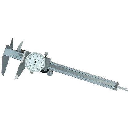
When measuring bearing measurements, they should always be taken at 90-degrees to the parting line to determine the minimum clearance. If measuring the bearing wall thickness, use a special micrometer with a ball anvil to fit the curvature of the bearing ID. The best way to determine bearing clearance is to measure the bearing ID with the bearings installed in the housing and the bolts torqued to the specified assembly torque. Use a dial bore gauge to measure the bearing ID at 90-degrees to the parting line, then subtract shaft size from bearing ID to determine the clearance. If the dial bore gauge is zeroed at the actual diameter of the crankshaft journal to be installed, the dial bore gauge will then read clearance directly and the subtraction calculation can be eliminated. About .001" clearance per inch of shaft diameter is a good rule of thumb. Increasing that by about .0005" will add a little margin of safety when starting out, especially for rods. Example: .001" X 2.100 = .0021" then add .0005", so starting out set clearance at .0026" for a 2.100 shaft.
If clearance adjustments need to be made, use either an extra clearance part for more clearance or an undersize part for less clearance. It is permissible to mix sizes if less than .001" adjustment in clearance is desired. When mixing sizes for a select fitting: a) never mix parts having more than .0005" difference in wall size; b) and always install the thickest wall shell in the upper position if installing a rod bearing or the lower position if installing a main bearing. When working with a reground shaft, always measure assembled bearing ID's first. Next have a shaft sized to produce the desired clearance since there are no extra clearance parts available for undersize shafts.
When measuring a bearing ID or wall thickness, avoid measuring at the parting line. The diagram illustrates there is a parting line relief machined into nearly all bearing shells. This relief is to allow for any mis-match between upper and lower shells due to tolerance differences, or possibly resulting from cap shift or twist during assembly. To determine bearing wall eccentricity or assembled bearing ID ovality, measure at a point at least 3/8" away from the parting line.
When installing any bearing DO NOT ATTEMPT TO POLISH THE BEARING RUNNING SURFACE WITH ANY TYPE OF ABRASIVE PAD OR PAPER. Bearing overlay layers are extremely soft and thin – typically .0005" on high performance parts. These thin layers can easily be damaged or removed by an abrasive media. Because the overlay layer is electroplated, it may exhibit microscopic plating nodules that make it feel slightly rough. The nodules are the same material as the rest of the plated layer and will quickly be flattened by the shaft. Bearing surfaces can be lightly burnished with solvent and a paper towel if desired.
Arriving at the correct choice of a high performance bearing for any given racing application is much like determining what clearance works best. From past experience, our knowledge of the intended usage and common sense can guide us in making an initial choice. Next, we can fine tune the selection process based on those results. The information given here is intended to aid in the initial selection as well as the fine tuning process.
The following table serves as a brief overview of the features included in each of the special Clevite 77® brand high performance bearing series.
this cam buttons correctly installed but the retainer plate tabs have not been bent up to lock the bolt heads from rotating
fine (micro) debris circulating in the oil, can rapidly cause damage in any engine, use of magnets helps reduce this but a proper pressure cleaning of the block with all oil passage plugs and bearings previously removed and a rifle bore brush run through all oil passages is ALWAYS mandatory on a used or even new engine block.
(common if the oil passages in the block are not properly cleaned after engine bearing failure)
and less than quality crank journal polishing
read the links it should help
http://garage.grumpysperformance.com/index.php?threads/types-of-crankshaft-steel.204/#post-239
http://garage.grumpysperformance.com/index.php?threads/can-i-get-it-polished.9214/#post-33116
http://garage.grumpysperformance.co...shaft-journal-surface-finnish.2728/#post-9886
http://garage.grumpysperformance.com/index.php?threads/thrust-bearing-wear.619/#post-37676
http://garage.grumpysperformance.co...uring-crank-bearing-journals.5478/#post-16429
http://garage.grumpysperformance.co...ing-oil-feed-holes-in-cranks.4419/#post-11637
http://garage.grumpysperformance.co...ank-durring-short-blk-assembly.852/#post-1311
http://garage.grumpysperformance.com/index.php?threads/analyzing-piston-damage.16432/
http://garage.grumpysperformance.co...pes-of-crankshaft-steel.204/page-2#post-46231
these books should help
http://www.themotorbookstore.com/engine ... nting.html
http://www.rehermorrison.com/rmEngineBook.htm
Last edited by a moderator: