Cooling system Details

voodovette

Member
The cooling system for the old 468 previously in my car functioned very well with nothing but a MOROSO tall, intake manifold thermostat housing/filler with a rad cap. See below...


Now with the 523 I'm having a hard time getting the cooling system to settle down and my local rad shop whom I've delt with for over 25 years tells me I need a kinda strange looking combination 2 piece thermostat housing/ expansion tank device sitting up there because the fill point is higher than any spot on the rad.


Of course, they are not able to explain why it worked before without it, so I'm torn on what to do.

http://www.newyorkrestomod.com/category_s/1820.htm

Suggestions welcome
 

Attachments

  • Cooling tank Manifold mount.jpg
    Cooling tank Manifold mount.jpg
    70.9 KB · Views: 352
  • DSCF1971.jpg
    DSCF1971.jpg
    79.3 KB · Views: 352
excellent question,
lets look at a few points

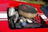
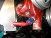
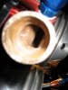
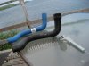
the part your looking at serves two major functions, it forces all air to surface in the aux fluid tank where its not lowering the radiator efficiency, and it add both a slight increase in surface area that allows air to absorb heat from the coolant, and slightly more coolant,, and maintains the full surface area of the radiator, to use to transfer heat , its possibly curing the symptom not the problem,and while in some cases that helps its basically a band aid approach,

finding the source of the heat will generally allow you to figure out a way to reduce the heat,if you can reduce the heat theres a lower load on the cooling system.
the first rather obvious source is the engine tune, if your ignition timing or your fuel/air ratio is off the ideal ranges heat increases, generally youll want the fuel/air ratio to be between about 12.7:1 and 14:1 for decent power production, and anything leaner than 14.7:1 generally increases heat, in the exhaust, mild detonation increases engine heat quickly, vacuum leaks tend to increase engine heat.
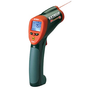
reading the spark plugs and use of an INFRARED TEMP GUN for tuning helps, it allows you to isolate the hotter areas and get a good idea as to the source, of problems. In most cases it also allows you to track the heat as its routed thru the cooling system and spot restrictions,
any restriction of coolant flow such as a restrictive T-stat,restrictive hoses, or less than efficient water pump will reduce the cooling systems potential, so check out those issues.

viewtopic.php?f=4&t=1337&p=2921&hilit=+infrared#p2921

ok first the HEAT generated is the direct result of BOTH the amount of fuel/air burnt PER minute and the engines internal FRICTION, both contribute a significant amount of heat.
cooling is the process of EFFICIENTLY TRANSFERRING the engine heat, produced by friction, from the OIL, that absorbs the heat and that transports the heat from the valve train, rotating assembly and bearings to the block, and from the block to the coolant where, that heat dissipated to the air flowing thru the radiator, from its surface fins & tubes where its again transferred to the air, and dispersed.

MORE INFO
viewtopic.php?f=57&t=853

viewtopic.php?f=54&t=2187

viewtopic.php?f=57&t=176

viewtopic.php?f=57&t=4230


to reduce heat theres several routes you can go,
you can reduce friction thru the use of the better synthetic oils
you can speed the heat transfer rates thru the use of thinner viscosity oil that flows thru the clearances faster
you can add a large oil cooler with a electric fan , and a baffled high capacity oil pan,as the combo will dissipate heat directly to the air ,lower the heat loads transferee to the coolant and radiator.
you can increase the size of the radiator, or its surface area thru use of larger tubes and more fins.
you can increase the air flowing thru it with larger fans or more efficient duct work
you can change the coolant type, or composition, and use additives like water wetter that increases the heat transfer rates by lowering surface tension, and you can add a high volume water pump.

CURES

as a general rule if the engines tuned correctly, and has the correct clearances and theres no mechanical issues, (you'll want to verify that carefully)
Obviously the cure is to have your system set up so the coolant in the radiator and the oil in the engine dissipate heat to the outside air at a far faster rate than the engine can add heat to those fluids
Generally the larger the surface area of the radiator and the higher is fluid capacity, the longer the coolant flowing thru it has to transfer heat, to the outside air, the larger the fans flow capacity and the tighter and more effective the duct work is around the fan, or fans the more air can be forced thru the radiator fins to absorb heat. id point out that a pusher fan in front and a puller fan behind the radiator will usually help, and a fairly cheap source of pusher electric fans is salvage yards(fords like taurus use them alot)
youll want to either add a large efficient oil cooler with a powered fan, and try to maintain, your oil temps at a steady 215F-220F range(as oil does far more of the actual engine cooling than most people will ever believe)
or add EITHER or BOTH a larger radiator or use more effective duct work and fans to force far more air over the radiator fins, to aid heat transfer rates

viewtopic.php?f=57&t=755

in a few cases a T-stat is restricting flow, and simple mods tend to have amazing results, since its free and easily done IVE always suggested drilling 6-8 1/8" holes in the T-stat flange area and in some cases it has produced remarkable reductions in average coolant temp ranges

viewtopic.php?f=57&t=348

BTW one frequently overlooked factor is your alternator size,in amps and wiring the alternator correctly, if your running a 70amp-100 amp stock alternator and using electric fans to cool the engine,its not going to provide the power required to spin the fans nearly fast enough to cool the engine like a better 200 amp alternator can


cooling is basically the process of transferring heat efficiently from its source, to the outside air flow as rapidly as possible thru the process of oil and coolant flow absorbing and transporting the heat from the hotter components to the, outside air, the faster, and more efficiently the fluids can absorb, transfer and release that heat, and the greater the surface area, and conductivity between the hot fluids, and the larger the volume of those fluids, in the heat exchange areas and the higher the speeds of the outside airflow the more likely you'll be to reduce the heat generated in the hotter areas, increasing the volume of oil and coolant in the system helps, increasing the surface area of the radiator, or adding an oil cooler or transmission cooler that adds an additional heat transfer surface to bleed off that heat to the outside air or allow the oil to release heat thru other surfaces than the radiators trans fluid cooler section will help, as will, adding a larger capacity oil pan and oil cooler, simply because the oil does much of the heat transfer from the hottest components to the coolant, so anything you can do to reduce oil temperatures tends to help. oil in the oil pan is exposed to air flowing over the oil pans outer surface and that will generally reduce its temperature, so the larger the oil pan capacity the longer the oil tends to be exposed to that cooling effect, naturally a real oil cooler with an electric fan will work even better but you can use both in tandum

COMMENTS? QUESTIONS?
 
Thanks Grumpy ....

As usual, your thoughtful comments and suggestions are much appreciated.

As would be the case in any Medical Doctors diagnostic approach, a thorough history of the patient is vital to the accuracy of the diagnosis and treatment, in terms of generating a positive outcome.

With that in mind, I apologize for not having provided more detail, particularly considering the broad range of "frames of reference" you have provided in your response, because I believe in retrospect it would have narrowed your focus.

Non-the-less, your excellent overview/reply reminds us all of the variety of elements that go into a balanced cooling system and furthermore, just how sensitive the cooling system can be, particularly when there may be either weak links or tipping point factors present.

I will draft up a history in Word, then transfer it over here in a day or two (after edits and refinements) for your consideration.

Thank You Sir.
 

Attachments

  • DSCF2052.jpg
    DSCF2052.jpg
    74.9 KB · Views: 318
My apologies for the long delay responding here, however rapid and unexpected financial and logistical
issues forced a long term deferral on this project, so just now digging out from all the drama after about
18 months and thankfully, still have the car.

Many of the points that Grumpy included in his notes herein are elements that we have experimented with
in our cooling system case study. For example, we have about a half dozen thermostats in various states of modification
that include conventional and "balanced" designs. Holes have been drilled into the perimeters of the
conventional ones and holes drilled into the inner cones of the balanced ones as well as portions of the flange
removed to facilitate bypass flow and reduce restriction which it seems to be very sensitive to.

I will expand further on the history of this cooling systems performance as time permits and will include
pic's of what we've been through. It's still not ideal, but it runs and drives and thank goodness, have not
"cooked" anything yet!


.
 

Attachments

  • Corvette.1985.ZR2.523.C.I.D.ZF6.Z51.jpg
    Corvette.1985.ZR2.523.C.I.D.ZF6.Z51.jpg
    278 KB · Views: 279
looking forward to finding out what youve done and what results youve had and looking at where we can improve things
 
Caveat: if this at all seems disjointed, please forgive me, but some memories of the
precise order of things are fuzzy. I'll do my best to correct and will respond to all Q's
in additional replies herein, but looking to build complete background history for
better diagnostic outcomes.

The first big "eye opener" with this was the initial attempt to change the coolant from
water and waterwetter to a 50/50 antifreeze mixture in anticipation of Canadian winter
storage.

At the point at which it was done the 523 C.I.D. had about 6 hours of run time and it was
very obvious that diminishing internal friction through break in use was reducing the heat
generated.

But back to the beginning for a moment...

To begin with, we were using the cooling components that came with the car as it had been converted
to the 468 many years ago, with the exception of no thermostat . (That copper 2 core rad and the front
pusher, rear puller fans were cooling the mild and 70,000 mile used 468 very well.) Our first run cycle
with the 523 began with 20 minutes until heat built up, and with every subsequent start extended by
about 10 minutes, until with about 2 hours of total run time the temperature settled down to an acceptable
185-190 and the system maintained that during a 2 hour, sub 3000 RPM rural route test run, still with
no thermostat.

(This is with a 9 litre fully baffled low profile oil pan, remote oil filter and external oil cooler, total oil system
capacity around 11 litres.)

We attributed this experience to the fact that we had more friction, more cubes, and a Siamese bore Bow-Tie
Mk V block, all of which had put the old system just slightly above it's tipping point for thermal transfer until
some of the new-build friction heat was naturally reduced.

So then, with seemingly stable heat, off we go to the rad shop to switch her over to antifreeze. It overheated by
the end of the block.(That's also the time they told me I needed the device described and pictured in the first
post of this thread.) It was at this point that I learned about the inefficiency of antifreeze to transfer heat compared to
pure water. Arguably and depending on who you talk to, between 20 to 35%, so evidently we had introduced
another tipping point. We went back to water and for the winter we drained the entire system and installed
ball valves on the lower block drains to make it easy for future coolant switches.

In the mean-time, as in following spring, last year, I'm wrackin' up more hours of drive/break in time when ever I can
squeeze them in between life's real priorities, and the heat just keeps on coming down to the point that it just barely
tops 160 with about 14 hours of total run time. (This is still with the exact same cooling system fill point as pictured
above, so no intake manifold expansion tank added yet.)

Time to add a thermostat as we're looking for a 180-190 temp operating range.

Next instalment "Thermostats as Flow Restriction Tipping Points"...


.
 
voodovette,

Thanks for the post ! I'm looking forward to your future posts, sounds like your results will be dependable and
informative. You are using a logical approach to determining the parameters that effect your cooling performance.
 
Introduction to Chapter:

"Thermostats as Flow Restriction Tipping Points"

The pic. include below has the modified versions of thermostats used in the
R&D phase of our attempts to regulate the operating temp of the 523
to between 180 and 190 degrees F.(It should be noted that the latest
version, similar to the centre sample below, but a 160, is absent as it is currently in the car.)
All these initial attempts were undertaken with the orig. copper 2 core rad
which prior to the introduction of the thermostats had been able to
maintain a 160 temp under light duty, sub 4000 RPM break in cycles.

From left to right we have two conventional 160's, a balanced 180, and
two conventional 180's.


None of them worked.

At one point or another in the test cycles, they would all cause engine heat to
slowly escalate, and once 200 degrees was reached, it would rapidly rise to 215
when the test cycle was aborted.

Basically, that was the point where the decision was made to upgrade the
rad to a 3 core aluminum.


.
 

Attachments

  • Thermostat.Modified.Samples.jpg
    Thermostat.Modified.Samples.jpg
    208.6 KB · Views: 265
so what your really saying is the T-stats used had no real effect because even when full and constant flow rates of coolant thru the system were maintained the radiator itself could not dissipate the heat fast enough to allow the t-stat to have any value in controlling the flow of coolant or its temperature.
remember the T-stats basic function is to slow coolant flow thru the radiator and engine block up too, but not above the pre -set coolant temp range the t-stat is designed to open at.
to function correctly the radiator must be able to transfer heat to the outside air flow faster than the engine produces heat in that coolant flowing thru the system, the t-stats function is to bleed in slightly cooler fluid in a controlled manor as needed to maintain a MINIMUM temp that the t-stats designed to maintain, once the t-stats open it has, or should not have any effect, as the coolant is already up to or above its designed opening temp. requirements ,so its remaining open and should be a minimal restriction to coolant flow.if the system doesn,t cool effectively, its simply because the system has no reserve of cooler coolant to draw from, or the air flow thru the radiator surface areas is to small to effectively transfer the heat from the coolant too the air flow and the mass of coolant in the engine and radiator is too low too absorb the heat in the engine and transport it and release the heat at the required rate,as it passes thru the radiator or the radiator passages fin count or surface areas or coolant flow rates to slow
this is the most consistently accurate I.R temp gun I've used for testing[/img]
42545.jpg

http://www.testequipmentdepot.com/e...1100200223789&utm_content=All Extech Products
INFRARED TEMP GUN


Cooling-System.gif
 
Last edited by a moderator:
None of them worked.
None of them worked, but did some modification work better than the others ???
Was there anything that you learned that can be used later ???

BTW, let me know if I can help with the graphics. As an example I did this one, just in a larger version. Also I can
help with exposures that are not quite right, build Excel spreadsheets, tables and graphs.


RingEndGapDeburring02.jpg
 
We reasoned that because the system without a thermostat could maintain a 160 F
coolant temperature with break in test cycles of up to 3 hours continuous running,
with RPM range up to 4000 pulls, that the presence of the thermostat represented
a sufficient flow restriction capable of inhibiting the rad from radiating an undetermined
amount of heat, but enough that it was a tipping point towards "failure". It seemed to us that at full
unrestricted flow volume, there was enough heat exchange, but at any reduced flow volume
there was not enough cooling of the reduced flow volume to compensate for that loss of
volume.

The conclusion therefore was that we needed a rad that could radiate, disipate, or othewrwise
get rid of enough heat within the flow volume of the system with a thermostat in place
and at whatever restriction that might represent compared to flow volume without a thermostat.

As one of our gang said ... "The thermostat is not "transparent" within this flow system."
 
your bring up a point most guys fail to realize, and thats the flow rate thru the radiator maters a great deal!
yes most t-stats are restrictive and there is a marked difference in flow rates between brands
most guys seem to think that if the slower flow allows more heat to be absorbed and eventually transported by the coolant , once the t-stat opens and allows flow, the same slower flow rate, that allows the coolant spending more time, in the block getting hot is also allowing the coolant in the radiator releasing that heat, its absorbed, to release that heat, so it will effectively be an effective trade -off resulting in no major gain or loss in average heat transferred, but the truth is that an effective and efficient radiator and shroud and fan assembly can pull a great deal of heat from the surface of the radiator fins with very high efficiency, and the air flow rates and outside air temps , do effect that heat transfer rate or efficiency, and allowing the coolant to boil or get close to the boiling point greatly reduces its ability to absorb heat from the engine, as any place the coolant can boil the areas effectively insulated by the lack of direct constant surface contact with the coolant flow , if that is allowed to happen temps can increase rapidly, the radiators pressure cap greatly reduces the tendency to allow the fluid to boil but there are additives that increase the fluids molecular contact with the internal surfaces making the heat transfer rates more effective.

74.png

http://www.redlineoil.com/product.aspx?pid=74&pcid=10

and obviously a larger , and more efficient radiator that holds a higher percentage of the coolant in its passages so it can transfer heat and a high volume water pump can further improve the cooling rates, as can additional auxiliary OIL and trans fluid coolers that can remove heat that might otherwise depend on the radiator to reduce its temperature
 
Yes, yes and yes.

Please note: These experiments are all being conducted with civil, state of the art, purified tap water
and Water Wetter as pictured above. There is no anti-freeze in the system now.

The new 3 core aluminum rad has more and finer fins and as a result, according to its manufacturer,
almost 30% more effective cooling surface. So then, the pump is the same, the dimensions of the rad
are the same as it is intended to be a direct replacement for an '85 C-4, so the hope was that the 30% additional
effective cooling surface would be adequate offset to the flow reduction presented by the thermostat
installed in the circuit.

The experience bore this out as with no thermostat we had a hard time getting it to crack 150 F on the first test
and we're now running a modified 160F "balanced" design t-stat, manually turning the front pusher fan off for
highway or steady state cruising where there's no stop and go.

Of course the object remains to achieve a fully automated/thermostatically controlled fan control system
that is reliable and trouble free, but...

eventually, that brings us back to the use of a coolant expansion/recovery device as shown on the "Cheetah"
above in the very first post of this thread.

We'll get to that soon, but first....

---------------- Part Two, Todays Project. --------------------------------


Here's the C-4, ZR-2 cooling system logistical quandary of the day...

I've got to get this thing running in the next couple of days for an upcoming club event
and I'd really like to upgrade the lower rad hose, because....

Here's a pic of the existing lower rad hose and the spring that is inside it. I'm told the purpose of that
spring is to prevent the hose from collapsing under suction. I've laid the hose out on my back deck rail
exactly the way it comes out of the lower rad outlet on the right, loops over the chassis brace above the front
crossmember, then arches up to the water pump inlet, on the left.


Twice, while playing with the rest of the system, changing rad, draining for winter storage, we've found that
spring has worked its way up into the opening/mouth of the Moroso High Volume water pump which seems
like a bad idea when you first look at the pump opening....


until you look at the following.....


Obviously, there is a transition from the big round hose attachment point to the
narrow interior slot. That means that the spring can only go so far before it is stopped by
this narrow constriction of the slot.

Component dimensions:
Measuring the width of the slot:
Using a piece of horizontally tapered cedar shim stock, we insert that into the pump inlet
until it is jammed...


then we remove the shim and measure the width at the
"Crush" point.


Result: slot is 5/8 inch wide.

The spring is 1.1/16 wide and the end has 4 very tightly wound coils
that are not possible to deflect with hand pressure.


Based on the above, we do not think it is possible for the water pump to ingest the spring,
however, when the spring has worked its way up into the pump, the entire section
of the hose over the first hump is now unsupported internally, so there may be a
legitimate concern that the suction of the high volume pump could collapse that portion
of the hose.

Also, does the spring represent another Flow Restriction "tipping point" that could be
an additional element of weakness/poor flow, in this system? Evidently there is enough energy
in the form of frontal resistance to push this stiff spring past two 90 degree bends.
We speculate that fact alone means it is creating an equally offsetting resistance to flow.

You can't buy a new hose with an internal spring for this application any more.

Question Is:
What is a good part number or other solution for this high flow application?


The blue sample above belongs to a fellow club member here.
He won't sell it to me.
It is a Goodyear "HighMiler" pt #61349HT and it is labeled on the hose
"Striation Resistant", which I'm told means anti collapse. It is an obsolete part
number up here. Anybody out there got a good idea for replacing this hose?
A Part Number? Adapt something else?


.

.
 

Attachments

  • Corvette.ZR-2.523.CID.Orig Lower Rad hose.jpg
    Corvette.ZR-2.523.CID.Orig Lower Rad hose.jpg
    85.4 KB · Views: 240
  • Corvette.ZR-2.523.CID.Water Pump.jpg
    Corvette.ZR-2.523.CID.Water Pump.jpg
    66.7 KB · Views: 240
  • Corvette.ZR-2.523.CID.Water pump inlet.Detail.jpg
    Corvette.ZR-2.523.CID.Water pump inlet.Detail.jpg
    67.6 KB · Views: 240
  • Water pump internal slot width.jpg
    Water pump internal slot width.jpg
    25.3 KB · Views: 240
  • Water Pump Measure slot width.jpg
    Water Pump Measure slot width.jpg
    40 KB · Views: 240
  • Corvette.Old Hose.Spring.Sample Replacement.jpg
    Corvette.Old Hose.Spring.Sample Replacement.jpg
    229.9 KB · Views: 239
http://www.goodyearep.com/productsdetail.aspx?id=11452

these guys list that hose


having gone this route several times Ive just used a universal hose with the spring molded inside the rubber,
gates brand has several hoses that will work but you need to have a friendly parts counter guy that will let you measure universal fit hoses on his rack , in some cases when you do engine swaps youll need to find two short hoses and splice them with a short section of stainless exhaust tubing and clamps to get the exact angles you want
 
Back
Top