Crankshaft problems?

69 chevelle

New Member
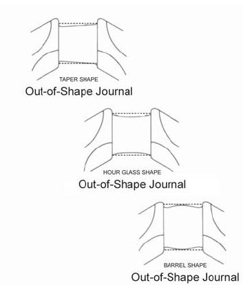
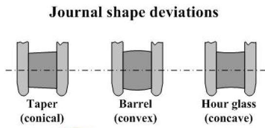
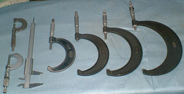
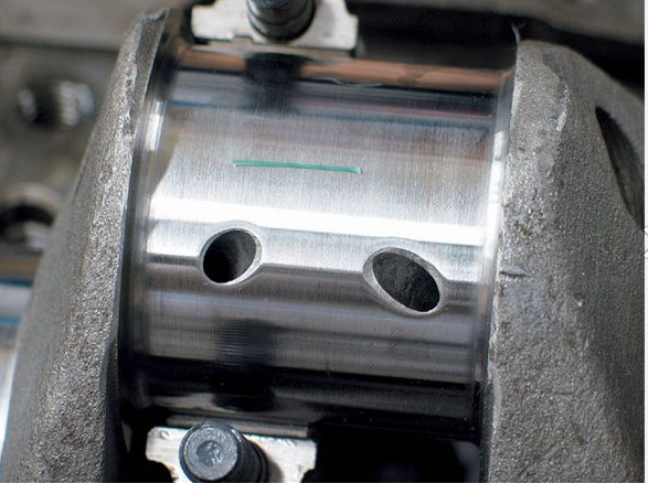
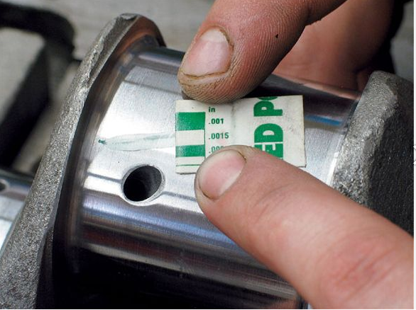
hey everyone don't know if I have a problem or not but hear goes,building 402 l78 big block,had crank shaft ground .010 under ,had rotating Assy, dynamic balanced ,in the process of assembly and miked the crank shaft journals and they have a taper to them especially the rod journals as Mitch as .001 from one side to the other. It's know it's not wright but will it cause problems or do I need to take it back to machine shop ,Bering clearance .003 on one side .002 on other.thanks for info in advance.
 
will it function like that?
yeah it probably will,
but, in my opinion ,its rather foolish to start out with a known minor problem thats easily cured, first remeasure carefully, if theres a verified issue get it fixed!
now you can, compensate, if the tapers consistent enough in dimension, or at least partially compensate by use of rod bearings that are .001 different on the smaller diameter end of the tapered journal, (kind of a REDKNECK CURE) but if it was my engine Id take it back to a good machine shop (a different one) because the original one obviously doesn,t give a crap about quality machine work and failed to catch and fix the issue while polishing the journals
but as I said, before in several threads, when you catch problems, stop and correct them!, never ignore the problem!
Id first state , congrats on verifying the clearances, as I,m sure most guys don,t bother and simply take the machine shops word and buy .010 over size bearings for the .010 under size journals and slap it together, never checking for actual clearances

if it was my engine Id get it polished to a standard under size and buy the correct matching size of clevite (H) bearings and use assembly lube and check carefully again with both mics and
plasti- gauge
when building any engine youll be far FAR ahead of the average guy doing that if you take the time and effort required to measure carefully and get the surface finish and clearances of all the moving surfaces to match the intended clearances and be sure to provide adequate pressurized oil flow in those areas requiring it, as almost all wear results from metal to metal contact, a condition thats usually prevented by providing a pressurized boundary layer of warm oil to the intended clearance between the surfaces as it was designed.
p33039_image_large.jpg

p33038_image_large.jpg

p33037_image_large.jpg


MEASURE CAREFULLY

bearingjournalz.jpg

journaltapers.jpg

dcp3.jpg

plast1.png

plast2.png

plas1v.jpg

plas2v.jpg


555-80593.jpg

11CheckingPiston.jpg

10CheckingPiston.jpg


plastigagefg.jpg


viewtopic.php?f=53&t=852&p=1311&hilit=checking+bearings#p1311


https://www.fordmuscle.com/fundamentals/plastiguage/

viewtopic.php?f=59&t=1026&p=4327&hilit=plasti+gauge#p4327

viewtopic.php?f=53&t=2726&p=7077&hilit=plastigauge#p7077

http://www.autozone.com/test-scan-and-s ... 36168_0_0/

http://www.hotrod.com/how-to/additional ... icrometer/

viewtopic.php?f=53&t=9214&p=43456&hilit=plastigauge#p43456
 
Last edited by a moderator:

On newly ground crank I would hope to see no more than .0002 inches and .0003
inches at the most. Sounds like a different machine shop is going to be a likely
choice if they can't do better that .001 inches taper.

Did you check for egg shape, is it out of round??? How did that look?

 
Back
Top