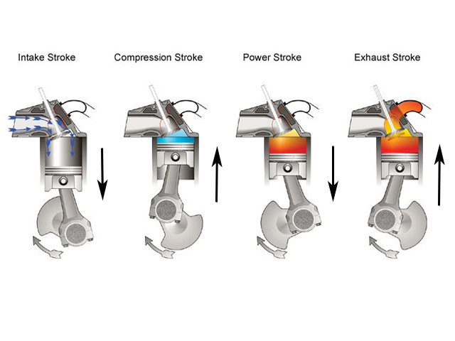
ok lets go thru the basics
static compression is a concept where the volume of the cylinder is measured from the lowest point the piston reaches in the cylinder (BDC +BOTTOM DEAD CENTER) compared to the highest point in its rotation (TDC=TOP DEAD CENTER) then you take that volume and compress it at TDC into the combustion chamber volume to figure the effective STATIC COMPRESSION RATIO
EXAMPLE
if we take a 383 with its 4.030 bore and 3.75" stroke and 5.7" rods
with a 67cc combustion chamber and a .023 deck(factory deck height)and use a .032 head gasket, we get a QUENCH of .054(not ideal)and a piston with 6.6cc of valve notch clearance
and we get a static compression ratio of about 10.2:1
use the calculators below
viewtopic.php?f=99&t=4458&p=12155#p12155
http://www.wallaceracing.com/cr_test2.php
http://kb-silvolite.com/calc.php?action=comp
the idea with dynamic compression is the piston can,t possibly compress anything in the cylinder until all the valves are closed, and they don,t close untill the pistons well up the cylinder on the compression stroke
http://www.wallaceracing.com/dynamic-cr.php
http://kb-silvolite.com/calc.php?action=comp2
http://www.projectpontiac.com/ppsite/co ... iew/16/30/
use all the same data in the calculator below but input the valve closes at 60 degrees past BDC or 60 degrees ABDC
and we get a dynamic compression ratio of about 8.5:1.
lets say we want a max of 8.2:1 cpr with that 383,because we have crappy gas and the engine has a dynamic cpr of 8.5:1.and we find it pings under heavy loads, what can we do?
well most guys will suggest a slightly thicker head gasket like a .040 , that gives you 8.35:1, you now RETARD the cam 4 degrees to close the intake valve ,later at 64 degrees ABDC and you find your new dynamic cpr is 8.1:1
play with the calculators, it will eventually become clear
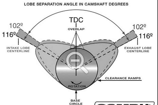
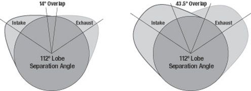
btw heres a cam timing chart, notice that a cam on a different LSA can vary the intake valve close point a great deal comparing identical DURATION CAMS built on DIFFERENT LSA(LOBE SEPERATION ANGLES
EXAMPLE
an INTAKE VALVE ON A 230 duration cam on a 105 LSA has this timing at .050 lift..open 14-closes 36
an INTAKE VALVE ON A 230 duration cam on a 114 LSA has this timing at .050 lift open 05 closes 45
http://www.crower.com/valve-timing-chart
piston location related to degrees of rotation and stroke
http://victorylibrary.com/mopar/piston_position-c.htm
http://www.wfu.edu/~rollins/piston/animation/graph_1/
I had a couple guys ask individual e-mail questions on this thread, so I realized I need to drop back to some basic concepts that seem to be over looked
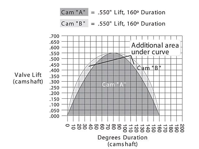
duration on a cam lobe is the factor that determines how many degrees the valve is off its seat and potentially flows gasses in or out of a combustion chamber over the piston.
lift on the cam lobe obviously dictates how far the valve opens ,
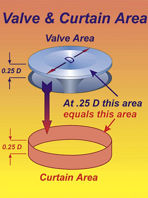
but its duration that determines how long its open, and once a valve lift exceeds about 1/4 its diameter its flow rates close to maximized, so the longer its kept over that lift ratio the more effectively it will flow . but remember the longer the duration used on the intake valve the further the piston moves in its rotation.
USE THE CALCULATORS
http://www.rbracing-rsr.com/runnertorquecalc.html
http://www.wallaceracing.com/chokepoint.php
http://www.wallaceracing.com/header_length.php
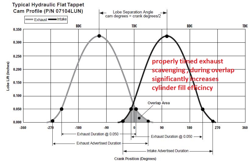
but keep in mind the port flow rate is restricted by both the intake cross sectional area and the duration , or time the valves off its seat WHILE theres a significant pressure differential between the intake port and the cylinder, the intake runner can be designed to induce inertial pressure in a set rpm band, but its the exhaust flow that's far more influential at helping to drag in the next intake charge into the cylinder as its fast moving gasses exit the exhaust, thus the overlap period is vitally important to maximizing cylinder fill efficiency, once you reach the rpm range where there's a significant inertial energy level in both the intake and exhaust to draw in and cause the exiting gases to be drawn out of the cylinder.
if you do some research you quickly find that the engines power curve very closely relates to its cylinder fill efficiency,
you also find that the intake port cross sectional area and valve size plus the cam duration ,lift and overlap have a huge effect on the engines ability to operate efficiently art any rpm range, because of either flow restriction if the port cross sectional area or cam timing are restricting flow or low port gas velocity levels, if the compression ratio,exhaust scavenging ,engine displacement or cam timing are not maximizing the flow rates in the ports
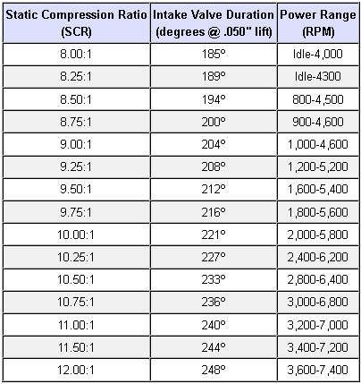
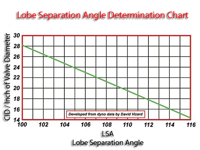
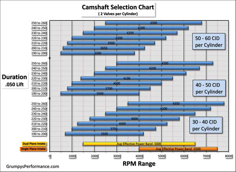
the chart above can be used as a rough guide to match cam duration at .050 lift and static compression in engines obviously other factors come into play so its only a rough guide
tighter LSA tend to increase the OVERLAP but thats not always the case
DURATION AND LSA are NOT necessarily related
related info you might want to read thru carefully
http://www.epi-eng.com/piston_engine_te ... torque.htm
viewtopic.php?f=52&t=5154
http://www.veryuseful.com/mustang/tech/ ... enging.pdf
viewtopic.php?f=52&t=148&p=34936&hilit=curtain#p34936
viewtopic.php?f=52&t=8460
viewtopic.php?f=52&t=727
viewtopic.php?f=52&t=3729&p=9689&hilit=ramp+acceleration#p9689
viewtopic.php?f=52&t=333
viewtopic.php?f=52&t=2627&p=6780&hilit=ramp+acceleration#p6780
viewtopic.php?f=52&t=181&p=5342&hilit=ramp+acceleration#p5342
viewtopic.php?f=52&t=1489&p=3360&hilit=ramp+acceleration#p3360