72novaproject STEVE is skilled at fabricating and welding he posted these fabrication pictures showing solution to clearance issue when the frame cross member prevented installation of low mount alternator
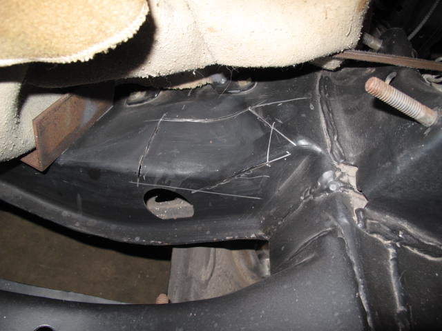
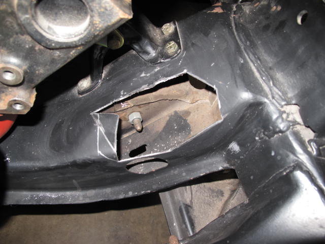
This is one of my recent fabrications that were not anticipated but I enjoyed doing it. Despite my research it seems these cars do not readily accept a low left mount alternator. I had to section the front cross member to have clearance.
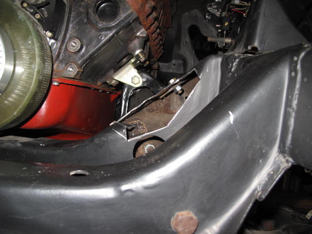
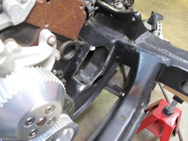
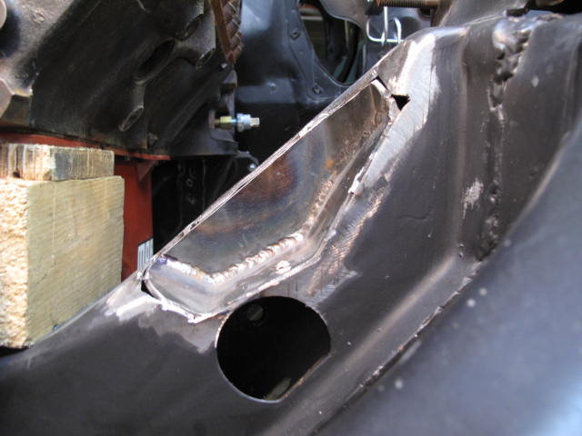
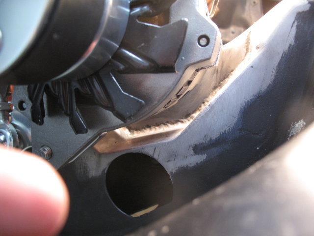
This was the original plan for the cuts. It would at least allow me to mount the alternator to work out the belt alignment
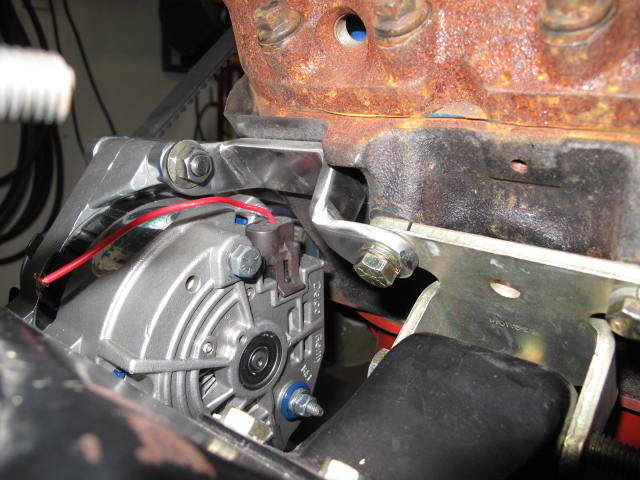
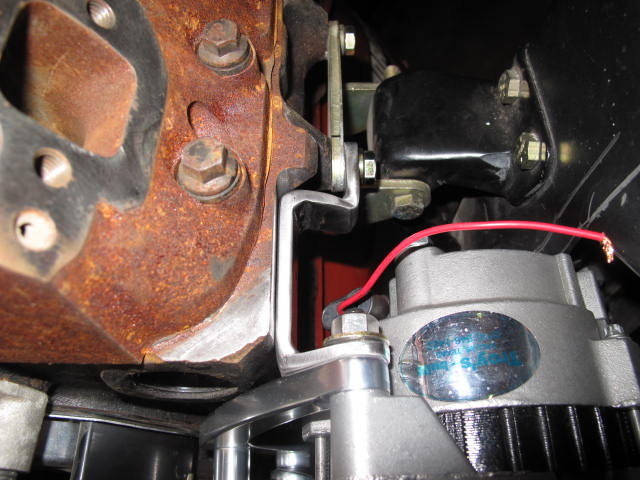
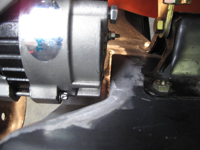
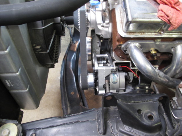
After being able to bolt on the alternator I had to fabricate this bracket to stabilize the cheesy Billet Specialties alternator bracket. Any belt tension at all would pull the alternator out of alignment with the crank and water pump pulleys on two different axis. The alternator shaft would move up and closer to the crank. I made the additional bracket from ¼†steel plate.
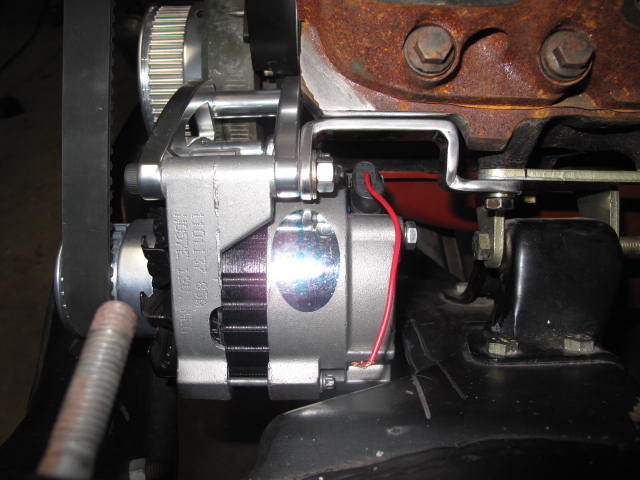
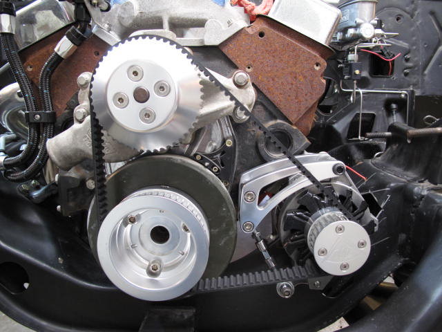

This is the cog belt drive system I decided to use on this car. I got it from “Miller Speed†and Alistair Miller is a great guy to work with. It uses a 1†timing belt and he has these systems installed on land speed cars that turn 12,500 RPM. I shouldn’t have to worry about slinging alternator belts anytime soon at only 6,500 RPM.
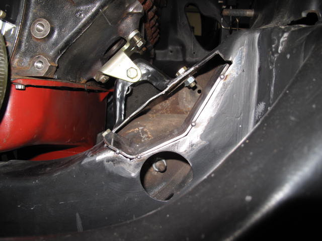
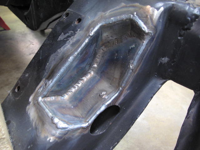
Once I worked out the alternator alignment issue it was time to restore the strength of the cross member. I started by fabricating the lower horizontal surface and tacking it to the cross member. I placed the tacks so I could cut them back out easily. Everything was left a little long so I could trim it once the vertical piece was built.

The vertical piece was a little challenging. Just the cardboard template was hard enough to make because of all the angles. Oddly, once I transferred this to 1/8†steel it fit almost perfectly the first time out of the bench vice. I cut it out with my home made band saw.
I had some help on this from the “Hot Rod Wednesday†crowd and they moved faster than the camera man so I missed photo documenting a few steps. Two heads are better than one but this is ridiculous.
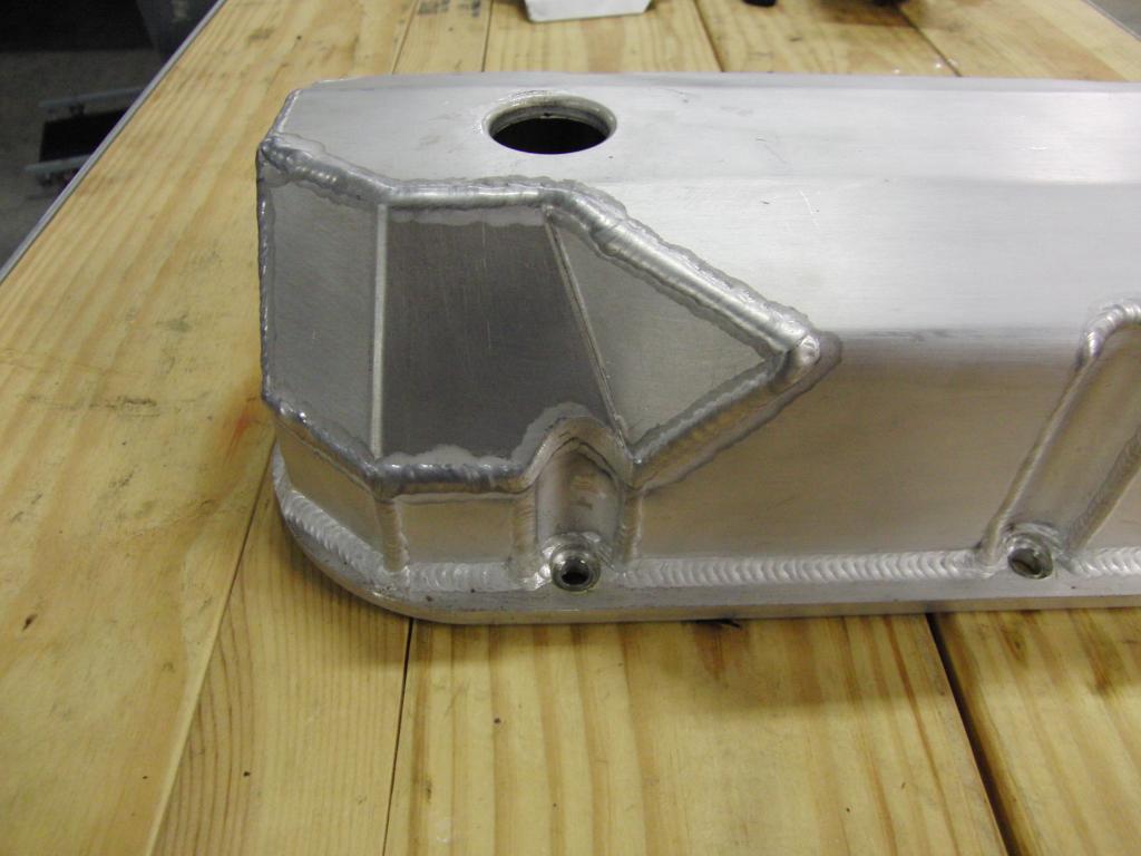
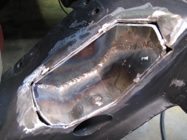
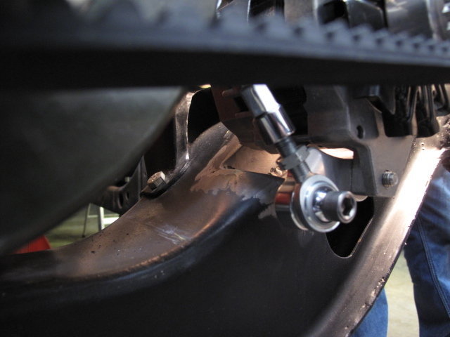
We cut and fit the vertical piece and tacked it to the horizontal piece in the car. Then we cut the tacks and took the entire thing out as an assembly. The horizontal and vertical pieces were TIG welded together on both sides and then put back in the hole for final fitment. It was then put back in the hole and tacked in. Note that all joints are prepared in such a way to allow for full weld penetration. Just to be safe we completely re-installed the alternator to be certain we had clearance. Then it was fully welded and metal finished.
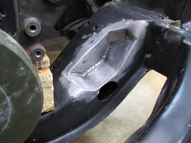
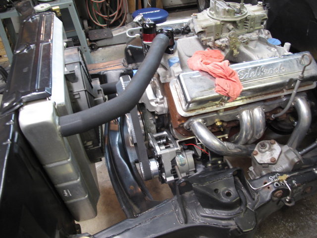
Once it was all put back together the modification is hardly noticeable. My sons think this is one of the coolest things I have done to this car. I think I wish I could have found an alternator bracket that would fit.
This is one of my recent fabrications that were not anticipated but I enjoyed doing it. Despite my research it seems these cars do not readily accept a low left mount alternator. I had to section the front cross member to have clearance.
This was the original plan for the cuts. It would at least allow me to mount the alternator to work out the belt alignment
After being able to bolt on the alternator I had to fabricate this bracket to stabilize the cheesy Billet Specialties alternator bracket. Any belt tension at all would pull the alternator out of alignment with the crank and water pump pulleys on two different axis. The alternator shaft would move up and closer to the crank. I made the additional bracket from ¼†steel plate.
This is the cog belt drive system I decided to use on this car. I got it from “Miller Speed†and Alistair Miller is a great guy to work with. It uses a 1†timing belt and he has these systems installed on land speed cars that turn 12,500 RPM. I shouldn’t have to worry about slinging alternator belts anytime soon at only 6,500 RPM.
Once I worked out the alternator alignment issue it was time to restore the strength of the cross member. I started by fabricating the lower horizontal surface and tacking it to the cross member. I placed the tacks so I could cut them back out easily. Everything was left a little long so I could trim it once the vertical piece was built.
The vertical piece was a little challenging. Just the cardboard template was hard enough to make because of all the angles. Oddly, once I transferred this to 1/8†steel it fit almost perfectly the first time out of the bench vice. I cut it out with my home made band saw.
I had some help on this from the “Hot Rod Wednesday†crowd and they moved faster than the camera man so I missed photo documenting a few steps. Two heads are better than one but this is ridiculous.
We cut and fit the vertical piece and tacked it to the horizontal piece in the car. Then we cut the tacks and took the entire thing out as an assembly. The horizontal and vertical pieces were TIG welded together on both sides and then put back in the hole for final fitment. It was then put back in the hole and tacked in. Note that all joints are prepared in such a way to allow for full weld penetration. Just to be safe we completely re-installed the alternator to be certain we had clearance. Then it was fully welded and metal finished.
Once it was all put back together the modification is hardly noticeable. My sons think this is one of the coolest things I have done to this car. I think I wish I could have found an alternator bracket that would fit.