This is going to be a long post. I have one running elsewhere for the past year now and it grew into a very long post. I'll try to gather pictures of several past jobs to show you the differences and options you can do or have done.
Differentials have been a mysterious unit for most corvette owners. Going beyond chaning the oil is not where most owners go. Thinking a shop will do what you want or expect can be a very expensive disappointment.
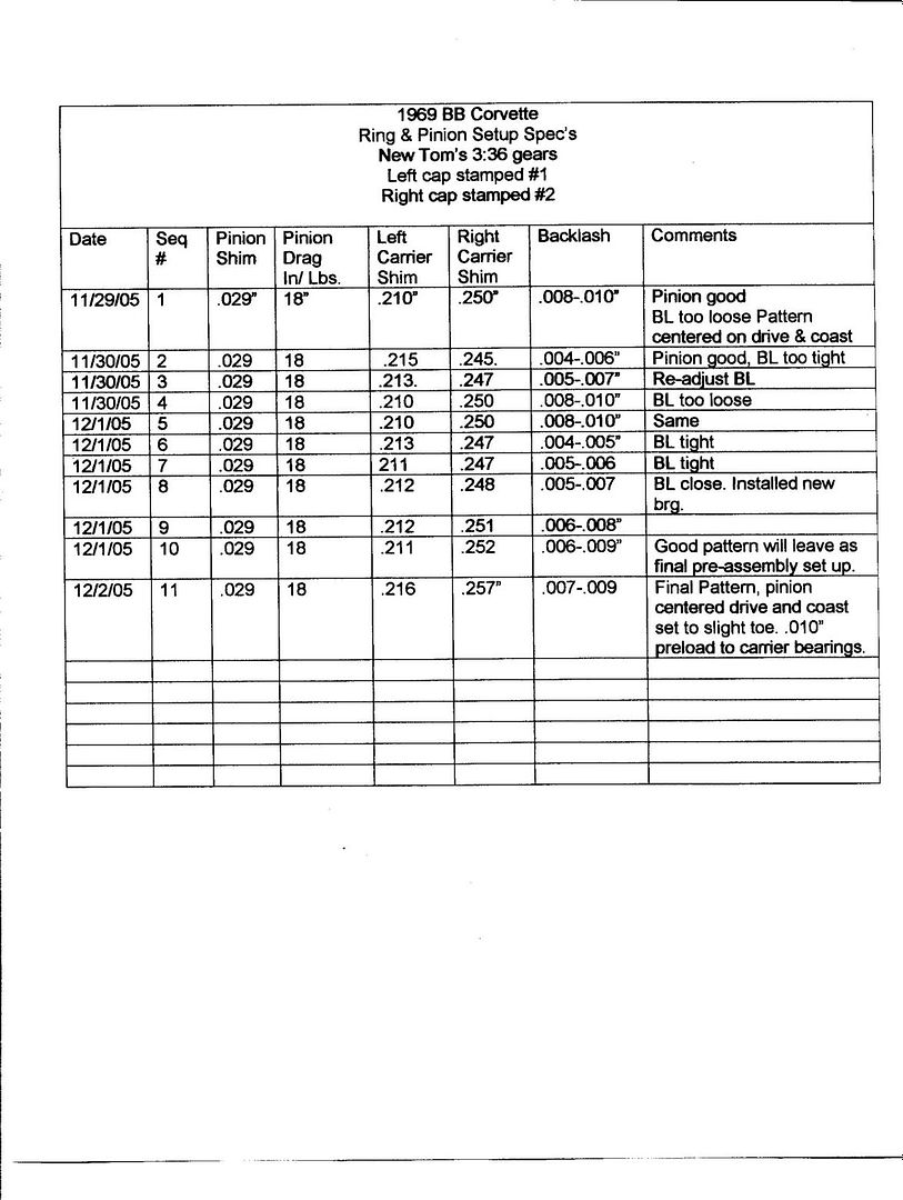
If you follow this thread along with the GM overhaul manual of the 60's - early
70's it will become more clear. I have a paper I wrote as well, some vendors even requested it. The procedures in the paper will follow this thread.
The point of this and all my threads is the education of the corvette owner so they can make a sound decision as to if they want to tackle this job. You must be honest with yourself - do you have the tools, measurement tools, the time and a good place to work? Cost wise you'll save $500-$600 in labor but the big cost are the parts. I use the best and they cost the most. I suggest you use the best parts as well but that is your choice. If you farm it out ask what make the parts are before you commit. They are not all the same.
The 63 differential is different then the 64-79's. the cover uses a different fillplug, the bearing caps are not as strong, the posi cases were not the Eaton brand as used in the 65-79's. Look up my posi tuning thread for more info on posi's. I will not go into great detail on posi's in this thread. Once I post the pictures I will limit the text in order not to write a book here.
Lastly, this is the way I do the job. I did not invent it, just reworked it. There are many who do this, some may agree or disagree. I don't care, I have yet to see anyone else post this type of thread. I welcome it but I believe our goals are different.
If you have any doubts about your abilities to do this job, pay someone who knows what they're doing. Remember, I am not responsible for your work.
Ok, some of you may recognize these pictures.
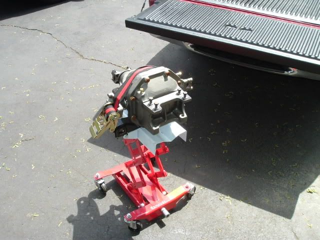
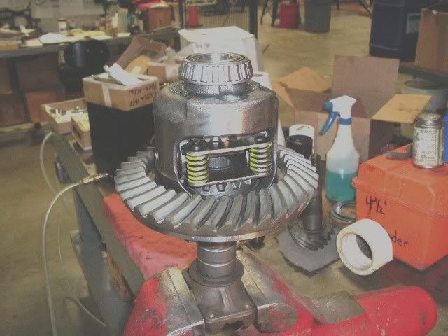
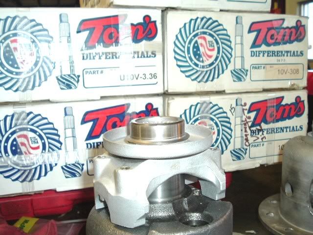
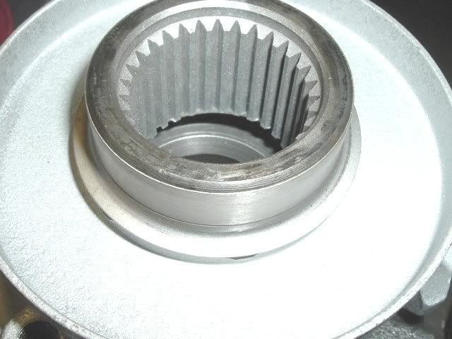
Here is a typical stock corvette differential. Out of the car and mounted on an engine stand. This really works great to overhaul these and the IRS pumkin is small enough to work around.
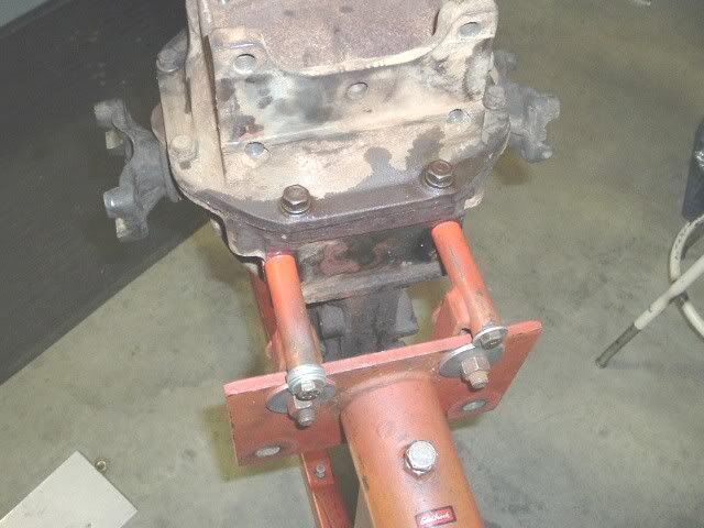
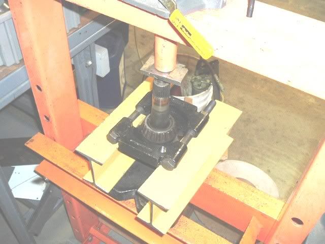
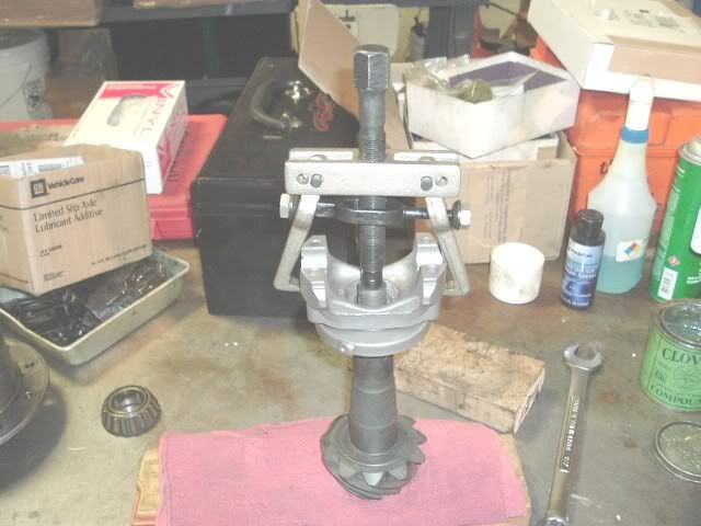
This is what I use to remove them with the car on jack stands. Works great.
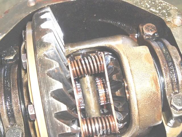
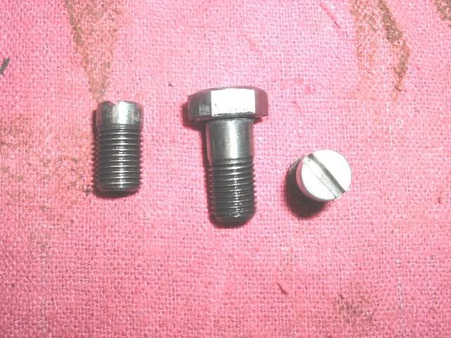
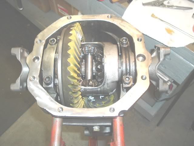
Here it is with the cover off. The early units use 5 line bolts not the GR8 6 lines, and the bearing caps don't have the cast in tabs like the one on the RH side here
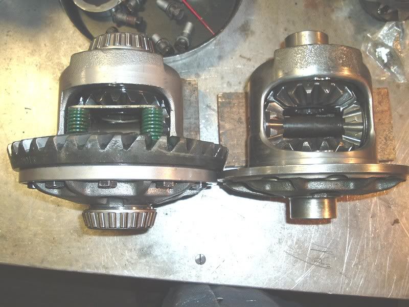
You hear a lot about 3 series and 4 series cases. The 3 series is the common one and the one you want. You can run 273-433 gears on it. The 4 series is a bit of a dinasour now as it was used with GM 411, 456, and up gears.
Here they are. The 4 series has a thicker flange to mount the ring gear.In this picture the 4 series has a 411 gear on it.
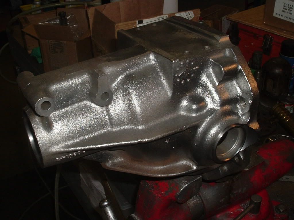
For comparision here is an 80-82 Differential. This is my only reference to them.
With the cover off take a look at it. They fail in the spring mounting ears and internally if someone used a bolt that was too long. They should not be cracked, leak, or show signs of a ring gear bolt flying around inside it! This one had the casting broken from a long bolt. The owner didn't know it as it was an eBay purchase. Be careful if you think buying a used diff is the answer.
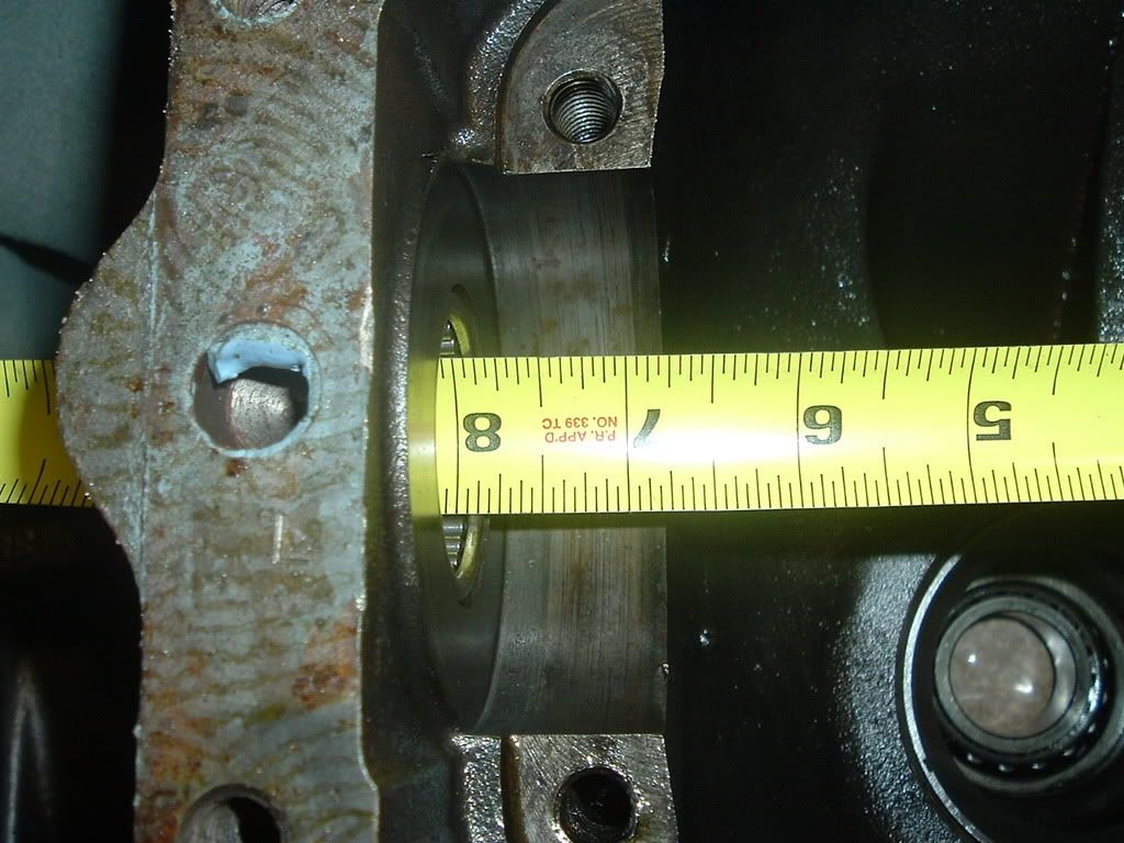
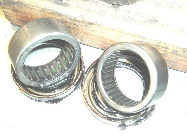
The early housings, 63-66 or 67?, were narrower between the bearing pads. Look in any catalog and they list master kits for '65-79, when the Eaton posi's were used. The shims in the common kits are not the same as the original thin shims and will not work- although some may try. You need to grind shims for the early housing to correctly dial in the backlash.
Here is what I'm saying.
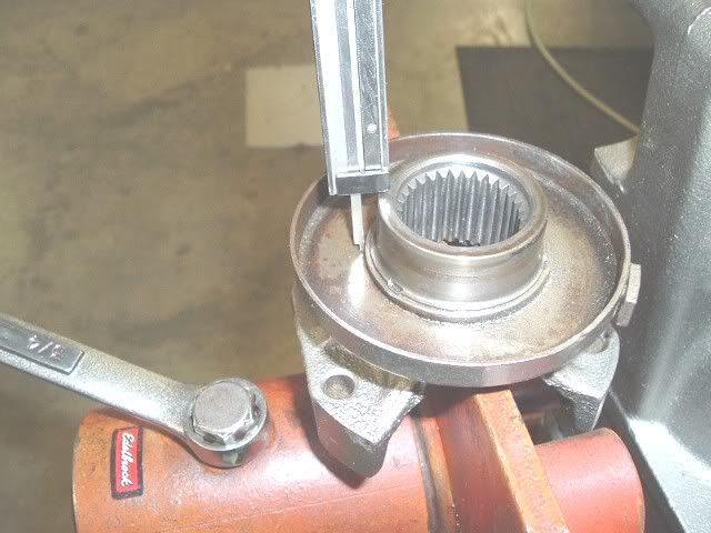
63 housing
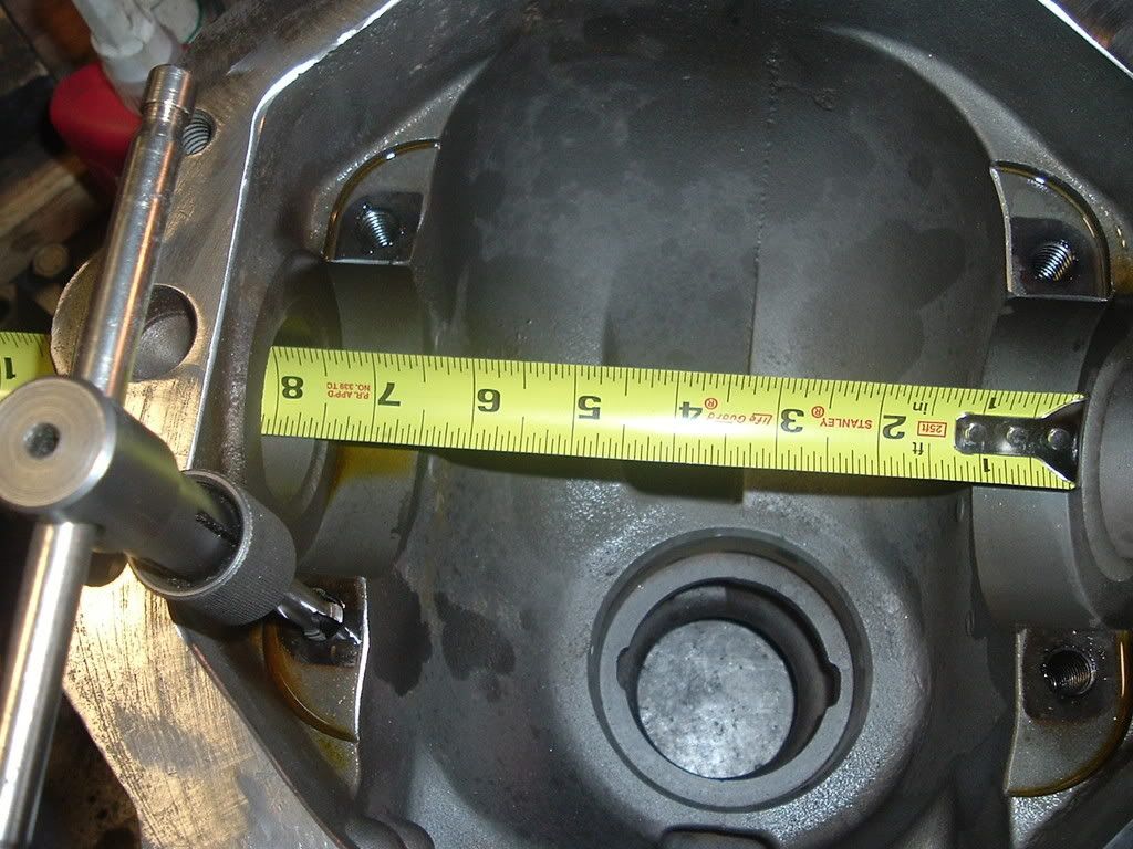
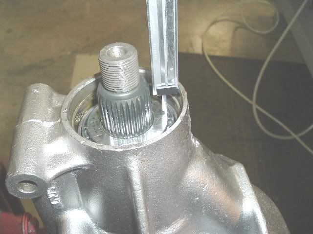
'69 housing
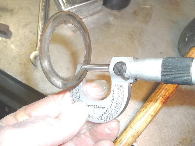
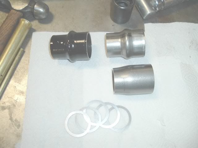
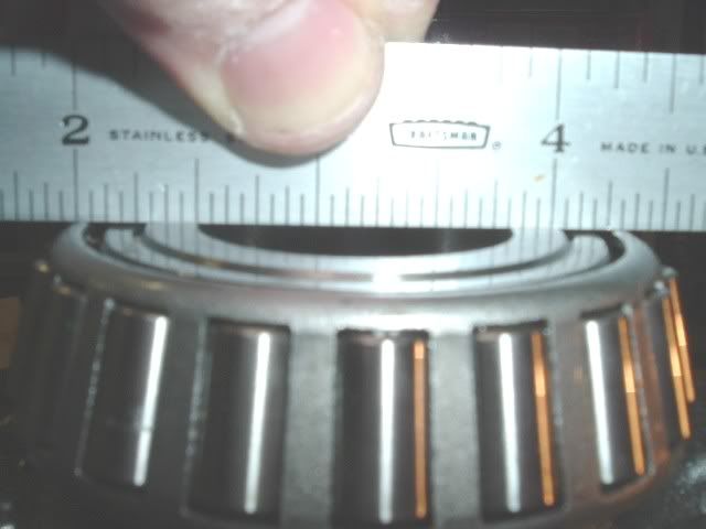
Here are the shims from the kit. They are stackable for ease in changing backlash setups. They run about .250" +/-.020"
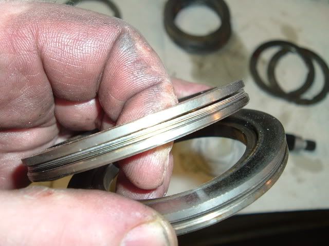
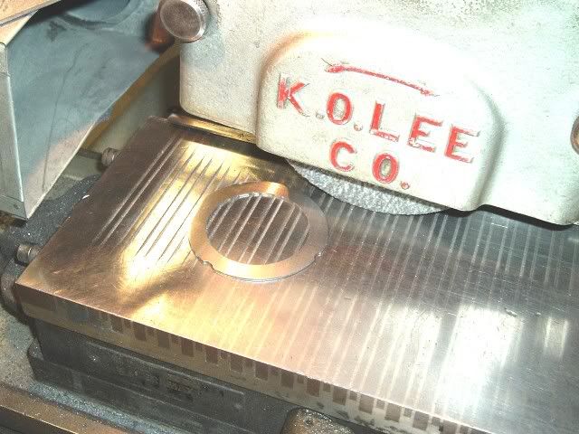
The early shims are in the .070"-.090" range and need to be ground to size on a surface grinder. Setting up an early diff,correctly, takes more time to do. Without access to a grinder you'll find all kinds of bubba setups.
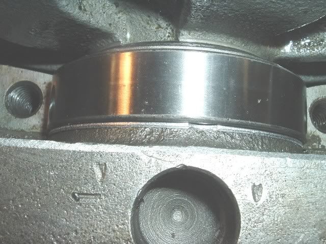
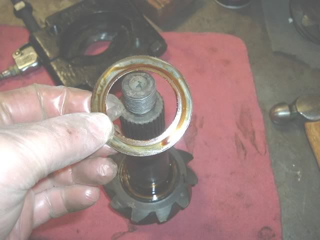
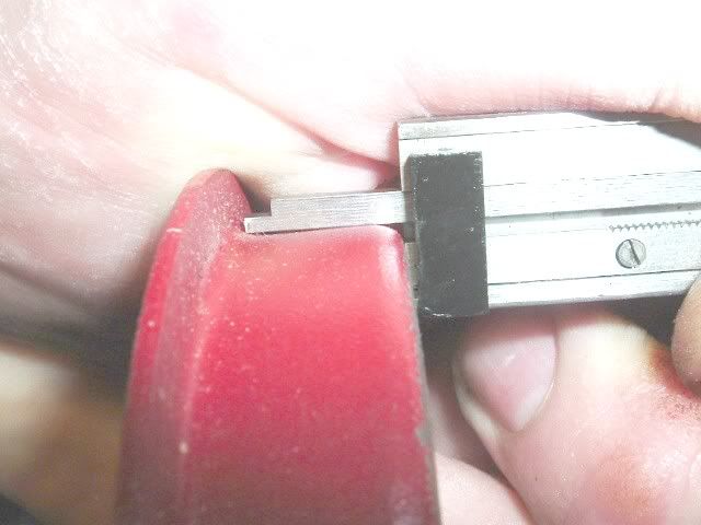
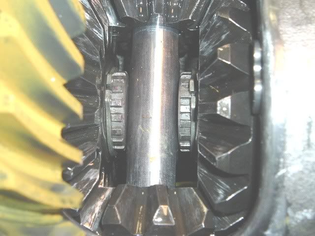
Here is a thin shim in place, you can see it is about .080"
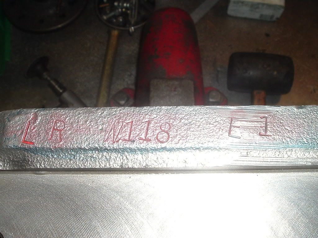
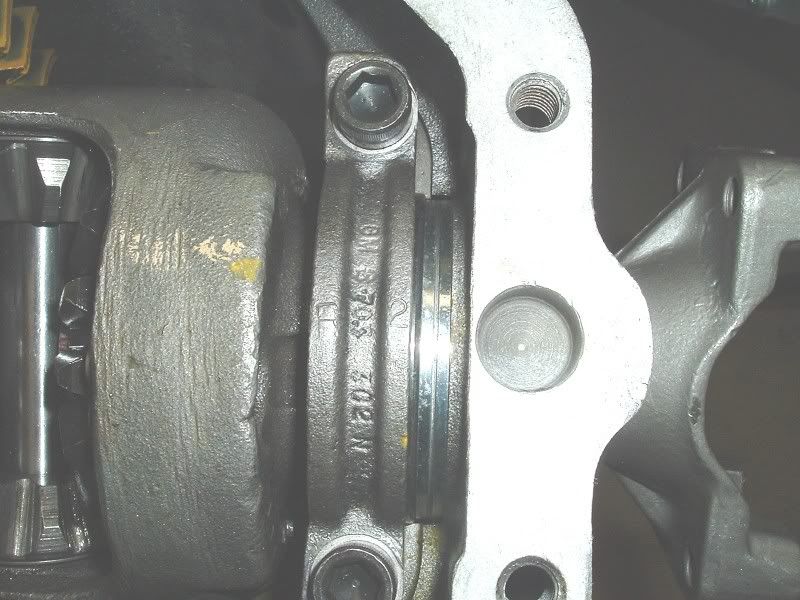
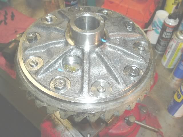
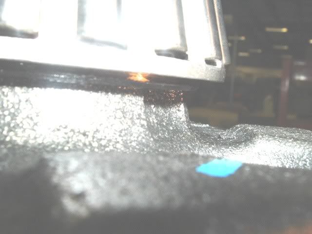
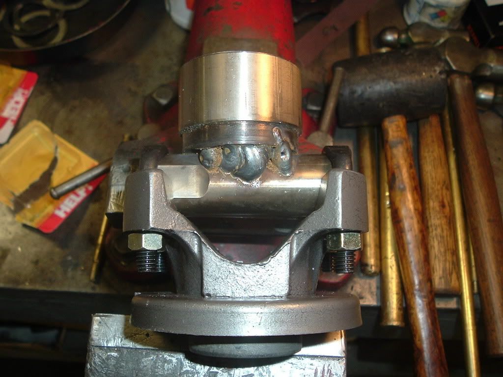
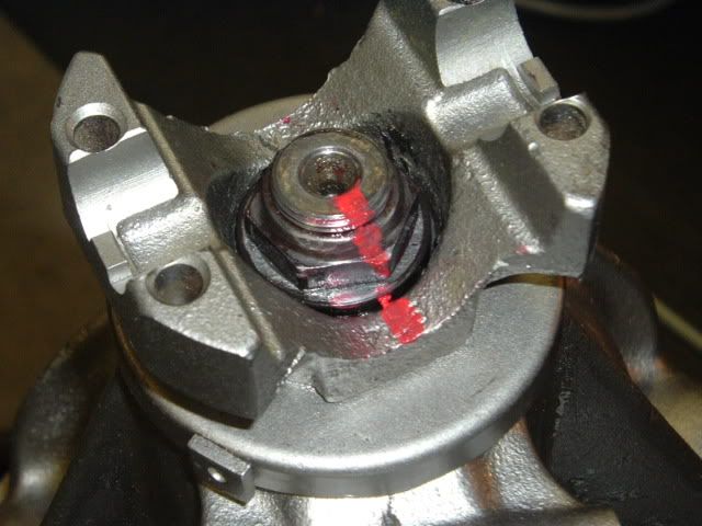
Before removing the case, witness the caps. Here is one I stamped an R into.The cap screws are also a mod I do.
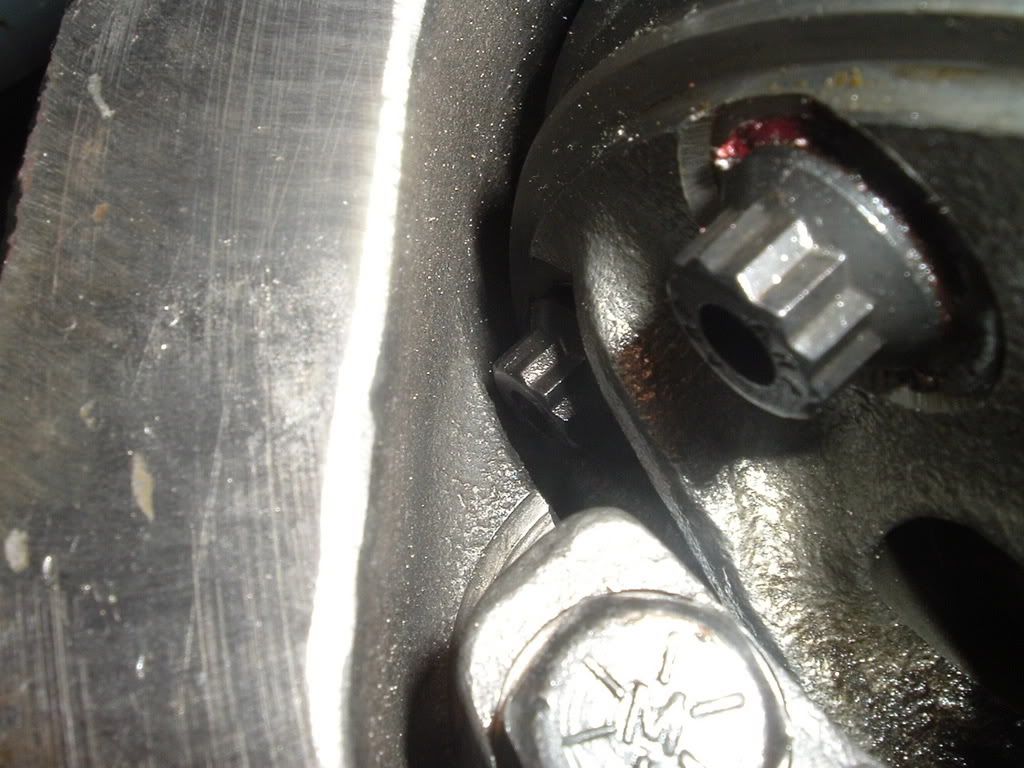
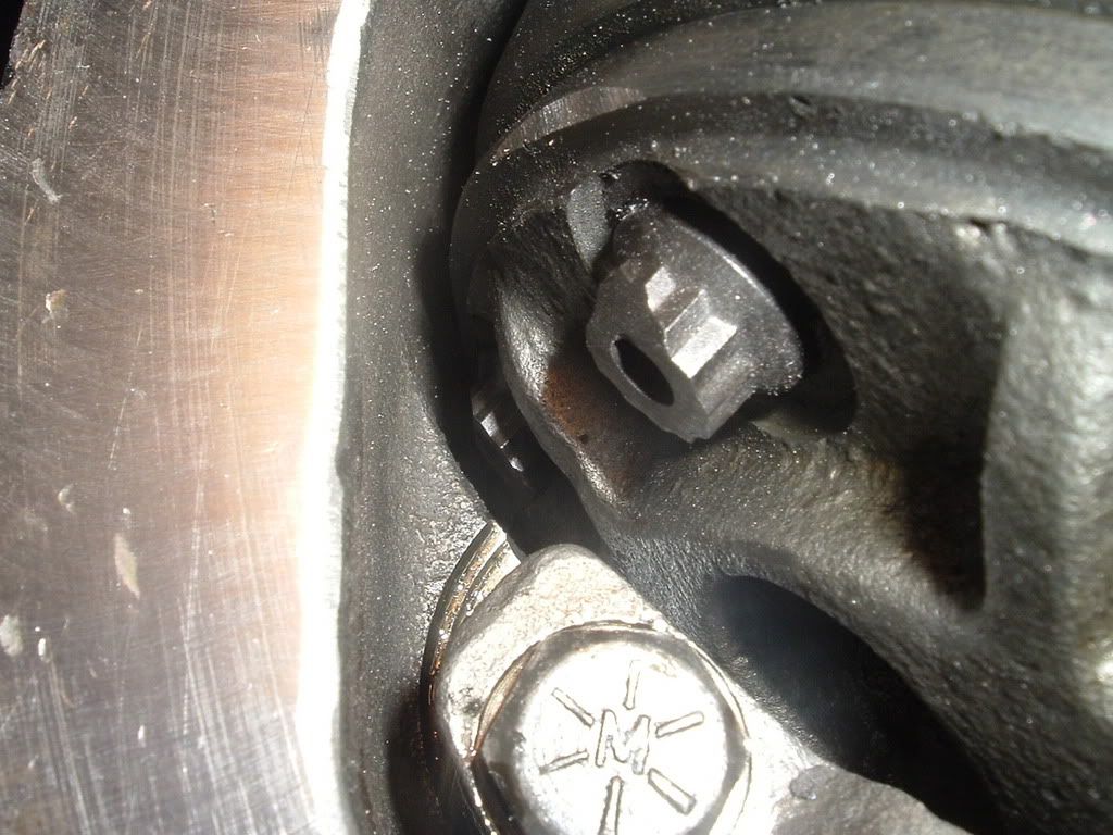
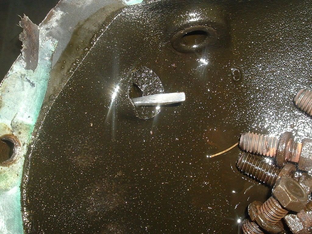
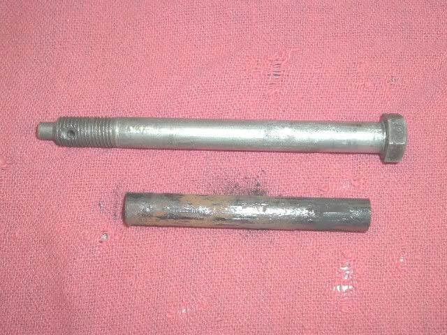
Look over the housing. Here is one I got in from FL. The front bolt was rust welded to the housing. I had to cut the bolt head off to remove the bracket. This bolt was really stuck in there. I had to cherry it with an oxy-acy torch to break it loose. Who said FL cars don't rust?
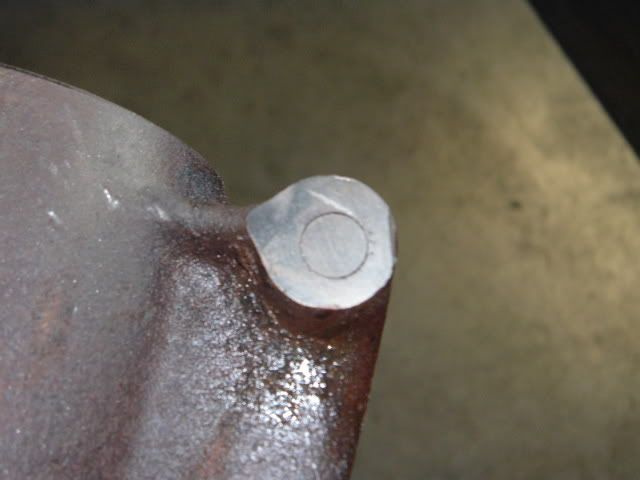
Here it is after I got it out.
One of the things I do is grind the sharp edges. Helps to prevent cracks and keeps your hands in bette shape
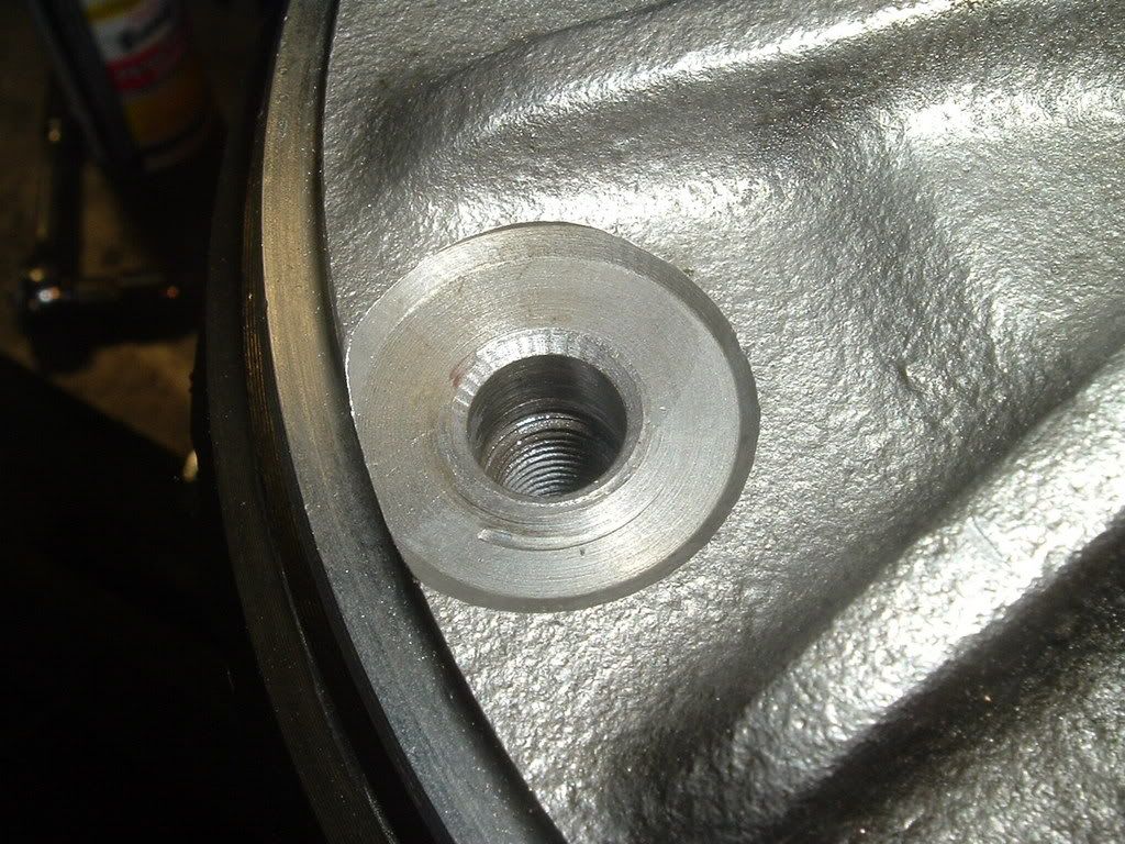
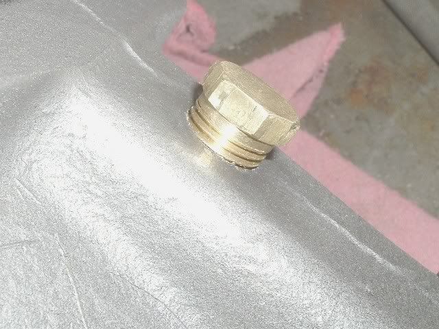
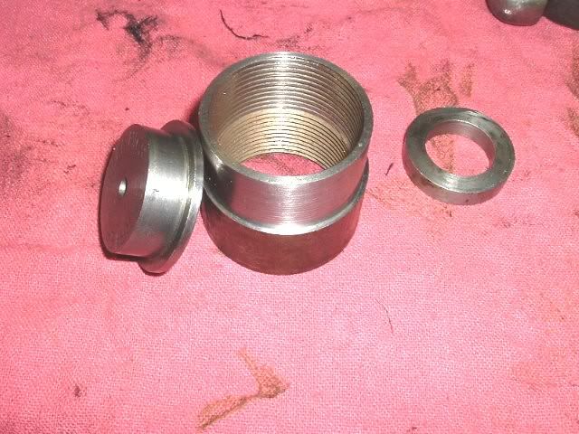
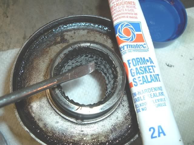
I also tap a drain hole in the housing if the owner wants it. This is done at NC, unlike some places that I've heard of charging up to $50. I tap them 1/4 npt and fit a brass plug. You cna use a magnetic plug as well but I like the brass. For aluminun tranny's I tap them 1/4 npt then use a 1/4 x1/8 bushing and 1/8 plug. This way you don't strip out the hole in the casting when wrenching on it. Here is one in an iron diff.
But this is all you need for these. If you have not tapped a pipe thread they are tapered so do not bottom out the tap like you would a machine thread or the plug will not seal. Tap and fit until you have about 1/2 the threads on the plug showing.
END OF PART 1
Differentials have been a mysterious unit for most corvette owners. Going beyond chaning the oil is not where most owners go. Thinking a shop will do what you want or expect can be a very expensive disappointment.
If you follow this thread along with the GM overhaul manual of the 60's - early
70's it will become more clear. I have a paper I wrote as well, some vendors even requested it. The procedures in the paper will follow this thread.
The point of this and all my threads is the education of the corvette owner so they can make a sound decision as to if they want to tackle this job. You must be honest with yourself - do you have the tools, measurement tools, the time and a good place to work? Cost wise you'll save $500-$600 in labor but the big cost are the parts. I use the best and they cost the most. I suggest you use the best parts as well but that is your choice. If you farm it out ask what make the parts are before you commit. They are not all the same.
The 63 differential is different then the 64-79's. the cover uses a different fillplug, the bearing caps are not as strong, the posi cases were not the Eaton brand as used in the 65-79's. Look up my posi tuning thread for more info on posi's. I will not go into great detail on posi's in this thread. Once I post the pictures I will limit the text in order not to write a book here.
Lastly, this is the way I do the job. I did not invent it, just reworked it. There are many who do this, some may agree or disagree. I don't care, I have yet to see anyone else post this type of thread. I welcome it but I believe our goals are different.
If you have any doubts about your abilities to do this job, pay someone who knows what they're doing. Remember, I am not responsible for your work.
Ok, some of you may recognize these pictures.
Here is a typical stock corvette differential. Out of the car and mounted on an engine stand. This really works great to overhaul these and the IRS pumkin is small enough to work around.
This is what I use to remove them with the car on jack stands. Works great.
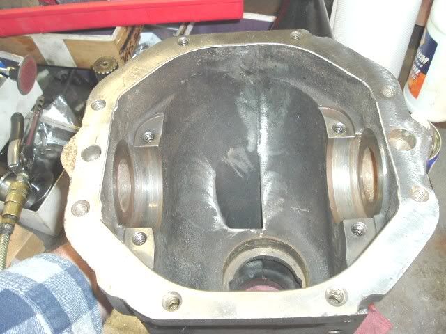
Here it is with the cover off. The early units use 5 line bolts not the GR8 6 lines, and the bearing caps don't have the cast in tabs like the one on the RH side here
You hear a lot about 3 series and 4 series cases. The 3 series is the common one and the one you want. You can run 273-433 gears on it. The 4 series is a bit of a dinasour now as it was used with GM 411, 456, and up gears.
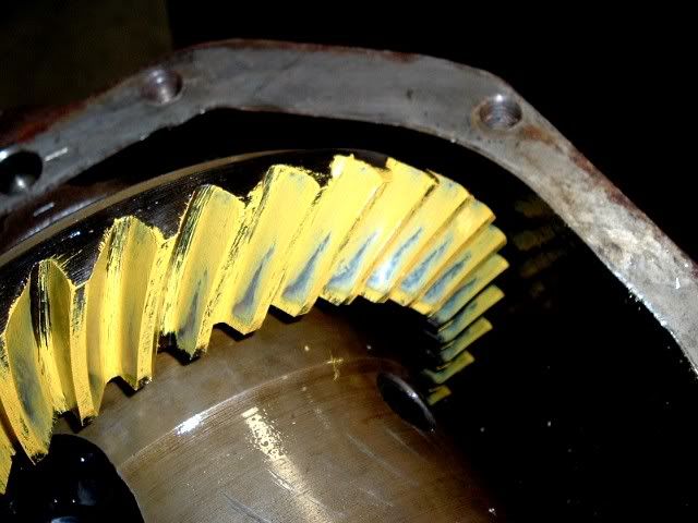
Here they are. The 4 series has a thicker flange to mount the ring gear.In this picture the 4 series has a 411 gear on it.
For comparision here is an 80-82 Differential. This is my only reference to them.
With the cover off take a look at it. They fail in the spring mounting ears and internally if someone used a bolt that was too long. They should not be cracked, leak, or show signs of a ring gear bolt flying around inside it! This one had the casting broken from a long bolt. The owner didn't know it as it was an eBay purchase. Be careful if you think buying a used diff is the answer.
The early housings, 63-66 or 67?, were narrower between the bearing pads. Look in any catalog and they list master kits for '65-79, when the Eaton posi's were used. The shims in the common kits are not the same as the original thin shims and will not work- although some may try. You need to grind shims for the early housing to correctly dial in the backlash.
Here is what I'm saying.
63 housing
'69 housing
Here are the shims from the kit. They are stackable for ease in changing backlash setups. They run about .250" +/-.020"
The early shims are in the .070"-.090" range and need to be ground to size on a surface grinder. Setting up an early diff,correctly, takes more time to do. Without access to a grinder you'll find all kinds of bubba setups.
Here is a thin shim in place, you can see it is about .080"
Before removing the case, witness the caps. Here is one I stamped an R into.The cap screws are also a mod I do.
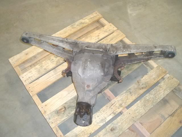
Look over the housing. Here is one I got in from FL. The front bolt was rust welded to the housing. I had to cut the bolt head off to remove the bracket. This bolt was really stuck in there. I had to cherry it with an oxy-acy torch to break it loose. Who said FL cars don't rust?
Here it is after I got it out.
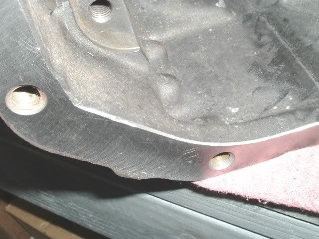
One of the things I do is grind the sharp edges. Helps to prevent cracks and keeps your hands in bette shape
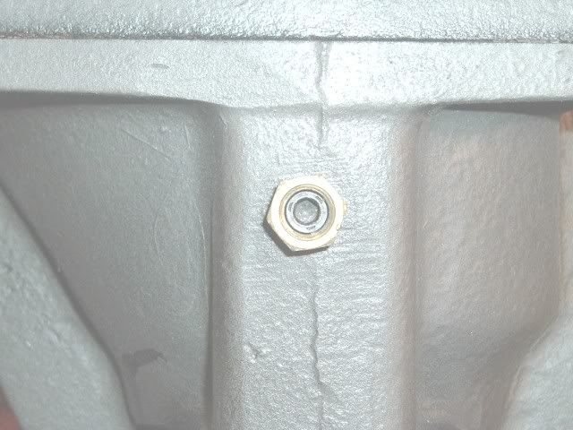
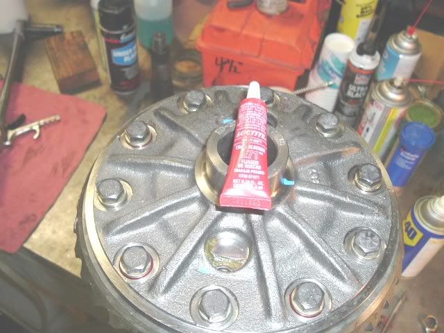
I also tap a drain hole in the housing if the owner wants it. This is done at NC, unlike some places that I've heard of charging up to $50. I tap them 1/4 npt and fit a brass plug. You cna use a magnetic plug as well but I like the brass. For aluminun tranny's I tap them 1/4 npt then use a 1/4 x1/8 bushing and 1/8 plug. This way you don't strip out the hole in the casting when wrenching on it. Here is one in an iron diff.
But this is all you need for these. If you have not tapped a pipe thread they are tapered so do not bottom out the tap like you would a machine thread or the plug will not seal. Tap and fit until you have about 1/2 the threads on the plug showing.
END OF PART 1
 :thud: