obviously port work on the runner divider section would help but your still looking at more work going that route, than adding injector bungs,and fuel rails to a Tunnel ram would involve
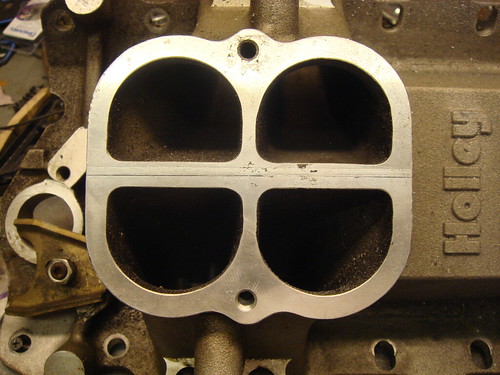
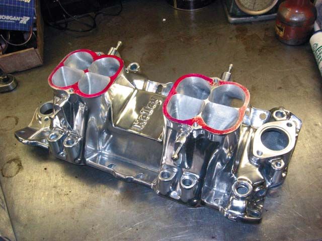
the idea of running individual intake runners to each carb venturie on a tunnel ram intake to reduce plenum area, and increase the rapid response to throttle changes comes up fairly often,but it won,t work unless all the carburetor venturies , both flow equal quantities of fuel/air mix all the time at the same fuel/air ratio, and all the throttle blades open at exactly the same rate. which is only something a few carbs are capable of doing and most of those are Holley dominator based designs designed for that application. Id also point out that the plenum under the carbs allows a great deal of flow sharing that allows you to feed a single intake runners from more than a single carb venturie, thats critical, because in almost all cases a single four barrel carbs single venturie is too small in diameter to effectively supply the needs of an engines cylinders.
If you do the research youll quickly find out about port stall speeds, and effective port cross sectional areas.
http://2.3liter.com/Calc2.htm#MinCross
http://www.wallaceracing.com/runnertorquecalc.php
http://www.wallaceracing.com/ca-calc.php
http://www.highperformancepontiac.com/t ... index.html
http://www.highperformancepontiac.com/t ... index.html
Determining Port Velocity and Volume
Determining air velocity is a useful part of testing. It is calculated as follows:
V = 1096.7* √¯H/d
Where:
V= Velocity in feet per minute
H= Pressure drop across test piece in inches of water (28†of water column being a standard)
d= density of air in pounds per cubic foot ( .075 pounds per cubic foot at standard conditions )
This represents the highest speed of the air in the flow path, at or near the section of minimum area (i.e. through the valve seat at low values of L/D, through the pushrod pinch, or minimum intake cross section, which ever is smaller).
Once velocity has been calculated, the volume can be calculated by multiplying the velocity by the minimum cross section area. Since we measure flow in cubic feet per minute, we use the first formula and divide by the cubic feet of cross section area: If we have an average cross section of 2.1 square inches:
Volume = Velocity (21,190 fpm) x Area (2.1 sqin x 1 sqft/144 sqin - converts sqin to sqft) = 309 cfm @ 28â€
Since we use feet per second in the flow measurement of ports the formula above the equation becomes:
V = 1096.7/60 (18.278) * √¯H/d
V = 353 feet per second (fps)
This should be the highest velocity measured in a port flow tested at 28†of water column.
Mean Piston speed in linear ft/sec from stroke in inches & RPM (David Vizard)
We want to find the average speed of a piston traveling up or down between TDC and BDC. Though it should be emphasized the piston speed peaks much faster than the value we will find, and it slows to a stop and perhaps reverses slightly at TDC & BDC, this mean (average) velocity figure is highly useful as a comparator. It's also useful to note for later that because of the secondary-linkage effect of the connecting rod, the piston spends more time in the lower 180* of the rotation.
Conversion of measurement units: stroke in inches divided by 12 to get stroke in feet : s/12 = stroke in feet
then take the stroke times two because the piston travels
the stroke's distance twice in a revolution, and by convention we measure rotational speed by full revolutions : ( S/12 ) x 2 or,
by taking the 2 inside the brackets, we get ( S /6 )
Then, since by convention, we measure rotational speed in automotives in a per minute format,
and we use a per second format for gas velocity, we need the revolutions each second, i.e. per
one sixtieth of a minute ,
so : ( S/6 ) x RPM/60 or cleaning up the formula by basic algebra :
S/360 x rpm = average speed of a piston traveling up or down between TDC and BDC
Mean Gas speed from piston speed (above) and "area/cross section quotient":
We want to find the average gas velocity over a stroke of the piston- a half revolution of the crank, assuming we have the cross-sectional area of a header tube, or of an intake or exhaust port. The latter can be approximated by measuring centerline length and port volume, and subsequently converting the units of measure to match the units for the motor bore area, in this case, square inches.
There are several ways of accumulating the measurements required, but the simplest starts with bore area which we are likely able to calculate easily, either working from bore diameter (‘B’) taken down to radius, & squared & multiplied by Pi, or from engine total volume divided by stroke and number of cylinders.
So: ('B' area/ 'P' area), where p can stand for either pipe or port
So we now have an existing area relationship mathematically described. To use some examples, if the piston had 6 inches area and the header pipe 2, we would have a factor of 3... and a design error on our hands: practice has proven that the relationship on the exhaust side should be between approximately 4.5, for high RPM 4-stroke modern motorcycle engines and dedicated auto racing power plants, to as little as 9 for those of us working with older low-RPM-oriented production power plants, and between 4 and 8 on the intake side.
This relationship is far better described/defined by what we are working toward a calculation of: gas velocity at RPM.
Gas velocity at RPM
We can calculate that by combining the two formulas. When we had bore area calculated above and looked at its relationship to port area, we could envision the gas achieving some unknown- but already apparent to be high- velocity as it exited through the port, or arrived through the port. What we didn't include was quantification of the volume being transferred each cycle: how deep the piston traveled to reach BDC, or how many times per second did it come back to TDC?
Again, our first formula has linear information, which combined with area gives us volume, and it has rate. Thus:
( S/360 ) x RPM x ( B area / P area )
let’s try some examples:
We spoke of an imaginary engine having pistons of 6 sqin and an exhaust header pipe of 2 sqin (you could also evaluate the intake side by using intake runner size). That's a pretty small bore diameter- 2.75" or 70mm - more motorcycle range than automotive, so lets say it's a 1000cc (61ci) four cylinder sport bike. The stroke is then calcuable to be 2.54", and we are doing calculations like this with power in mind, so let’s say that the RPM we wish to examine is 10,000rpm. The port area used was 2- we referred to the header pipe area, but that's an extension of the port; we'll start ignoring the difference.
So, we have:
( 2.54/360 ) x 10,000 x ( 6 / 2 ) = 212 ft/sec
and, as noted, that is too low a figure. In practice rules of thumb have developed saying that at peak power, the ft/sec figure should be somewhere within 280-380 exh and 240-355 intake.
Let’s take another example- a 350 cid v8 with a 1.5 OD diameter header pipe and a relatively mild state of tune that leaves us interested in its 5,000 rpm statistics. It has a 4.000" bore (area=12.57 in2) and 3.48" stroke, and the ID of the header pipe is approx 1.39" (1.52 in2) as in a typical 1.5" OD pipe with wall thickness deducted for accurate calculation.
So:
( 3.48 / 360 ) x 5 000 x ( 12.57 / 1.52 ) = 399.7 ft/sec
This result implies the motor is being revved slightly beyond its power peak and/or that larger headers would likely give more power at this and any higher rpms. As always, a trade-off exists, as the 1.5" pipes will have produced a greater power up close to this rpm, and may make it unwise to take that power advantage which has "accumulated" as the motor rpm's have risen under load, and trade it off for greater peak power.
The next available tubing size up - 1 5/8th's- is an 18-19% jump, putting the ft/sec figure @ 325, which is actually perfect for 5000, but progressively tending to be wrong as you look at increments of lower RPM.
The first header intend is for a motor with 3.64" bore, 3.5" stroke, being shifted at 4900rpm but with the emphasis on low end and midrange, so calculate using the rpm figure given, but emphasize the low and mid range by using higher ft/sec figure than I would otherwise.
3.50" / 360 x 4900rpm x 10.41" / 360ft/sec = 1.378 in2
So where does that leave us in picking a tube size? That figure is in square inches, so we divide by Pi, take the square root, multiply by two, & arrive at a dimension for ID. I add .049" x 2 for the walls to get the OD, and find it to be 1.42". We already figured I'd use 1.375" OD for several inches coming off the ports and do the remainder in 1.5". Now we’re less worried that the 1.5 need to be mandrel-bent, though we know the disadvantage of 'crush bent' is less related to simple loss-of-area type restriction and more the energy used in speeding up and slowing down the gases as they pass through cross section changes. Since this area of pipe figure is notably smaller than the stock port area as measured at the opening (~1.8 in2), it confirms I am on the right track in filling the port floor.
Since it's becoming apparent that the variable we are most likely to want to solve for is the port area, we need to reformat our equation to solve for port cross-sectional area when we have all the other figures. This requires setting the formula up with an adjustable ft/sec position, because depending on the character of the motor's use you will have different aims.
Starting from:
( S/ 360 ) x RPM x ( B area / P area) = ft/sec
or,
writing it on one line, since we are fortunate that order of operations is irrelevant here
S / 360 x RPM x B area / P area = ft/sec
It then holds that:
S/360 x RPM x B area / ft/sec = P area
Putting the formula to yet another use, you can measure the ports you have to see what RPM band they suit. Take soft wire, like solder, and measure the top length (beside guide) and bottom length, averaging them to get centerline length, then CC the port. You can now calculate average port cross section: take the CC's and divide out the length. Remember 16.39cc=1ci, convert the port volume into cubic inches before dividing by the length, assuming you used inches to measure centerline length.
The derivation of the formula I am providing for this requires you to find the reciprocal, but scientific calculators have that function
S / 360 x Barea / (ft/sec x Parea )= 1/rpm
So, some rules of thumb as far as desired gas velocities.
Highly developed ports such as those found in race specific castings can accept 10-20% higher velocities, due to the lack of flow differentials. In other words, they use the full port area, and to not have "hot spots": areas where the flow chooses to concentrate and which could become turbulent or supersonic if pushed beyond a certain speed. Also such engines are likely to have high compression which somewhat changes the dynamics of cylinder filling and emptying.
Figures shown are average velocity throughout the port, and references to effects are in the RPM range of peak horsepower.
240 ft/sec - intake - ram effect faint
- exhaust- scavenge faint
260 ft/sec - intake - ram effect moderate
- exhaust- scavenge weak to moderate
280 ft/sec - intake - substantial ram
- exhaust - scavenge moderate
300 ft/sec - intake - * ideal ram
- exhaust - substantial scavenge
320 ft/sec - intake - possible loss
- exhaust - * ideal scavenge
340 ft/sec - intake - likely loss
- exhaust - possible loss
Correcting Runner Length
Q: We have just got a sbc built and the engine builder had a blonde moment and has installed a sheet metal intake with way to large of runners on it. Needless to say the motor does not make the power we are looking for. My question would be if we are able to install a sort of insert and get the runner volume under control will we see a good gain in power even though the plenum volume is still large. It is a 366 SBC with Brodix canted valve heads 290cc 13.5 :1 comp. The total runner length is 12.4 "and needs to run at 6000 to 6500 steady WOT rpm. The runner volume right now is 600 cc and I figure that it should be about 300 cc.
A: With a 12.4" long intake tract (port and runner total length) you are tuned from 6800 to 8000rpm. This is well above your engines intended operational rpm range. This means your operating the engine at an RPM where the intake tract pressure pulse is either neutral or slightly negative. You may be neutral in this area so reversion might not to bad but it’s far from an optimum situation, now for the good news.
Depending on the manifold design you have, you can either increase air speed to band-aid the runner length or make spacers to put in the plenum to lengthen the runners. You really need .750 thousands to bring the manifold back into tune but that will take up a lot of plenum volume. If you’re out of tune the runner volume is secondary to air speed and wave tuning. I have done this many times and actually do it quite often. In many cases the results are astounding. Our 622 engine uses the Profiler 2/4 tunnel ram intake.
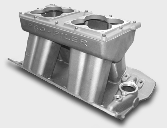
This manifold is tuned from 7400rpm to 8700rpm. The larger engines all operate from 6000rpm to 7500rpm and some as high as 8000rpm. So the engine is trying to make peak TQ at 5500rpm and peak power at 7500rpm. Using this manifold causes a hole in the mid range of the power curve because it’s "out of tune" there. I fill the runners to increase air speed as much as possible without hurting top end power. The result is a 45ft/lbs increase in torque and a 60hp increase in power through the middle of the power curve. The engine accelerates much faster and recovers on the gear change better. If I where able to put plates in the plenum to increase runner length instead of increasing air speed the result would be even more power and a broader power curve because I would not only have the proper runner volume but the proper tuned length as well.
The course of action we take as well as the end result will depend on the manifold design you have to work with. Sometimes I can band-aid them and sometimes I can’t. If you have measurements and pictures of the manifold it would help a great deal. I can talk you through it if you want.
Darin Morgan
R&D-Cylinder Head Dept.
Reher-Morrison Racing Engines