Individual runners w/o air filter...

Carlos

Active Member
Winter time...as usual time to work on a project.
The manifold of my SBC is leaking more and more, so I'll take it off and do the sealing.
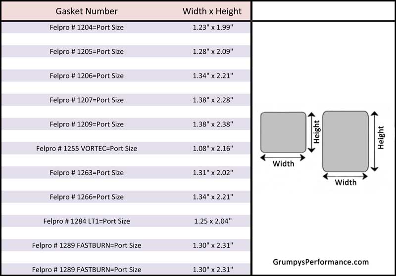
Btw...is there any "best before" date on the intake gaskets? I have mine sitting around for probably 5 years now, maybe better getting new ones?
Any recommendation ?

But here is the real main question for the experts....
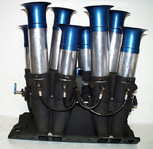
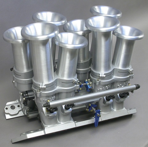
Since I added the TWM induction I did not find the time to go to the dyno for final tuning, what should happen in spring now :mrgreen: .

Due to lack of space I cannot add any air filter to my air horns, also... how ugly would that look like :) ?
However, after the first trip I found plenty of very little gravel sitting on my intake manifold, which made me a bit nervous.
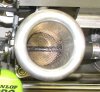
The only way to be a bit more on the safe side, I thought, is adding thin stainless mesh between the horns and the throttle bodies, so I had them laser cut to fit well.

Now-whilst I fully understand there is a restriction in air flow by putting the mesh in, I have no proof about any negative effect.
Theoretically I could calculate the restriction purely by the wire diameter of the mesh, however is that correct and meaningful? A round wire behaves different than a square one...

I heard many guys telling stories this mesh will kill the overall performance, where none of them ever had an own experience on dyno runs.
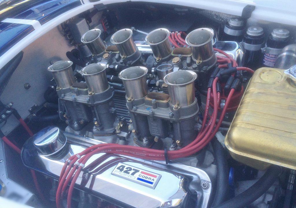
On the other hand side same guys are using air horns looking more like a simple sharp edged funnel, rather than a real air horn, which to my understanding impcacts performance as well (even more?).

So any help is really aprecciated, maybe there is even somebody who has experienc on a dyno :cool:

Thanks a lot

Carlos

PS: I might even do the testing with and w/o mesh on the dyno, but as they are sealed to avoid air being sucked in sideways, it is quite an effort to exchange them in a clean manner.
 

Attachments

  • TWM induction w dunlops.jpg
    TWM induction w dunlops.jpg
    439.1 KB · Views: 19
  • TWM induction w dunlops-2.jpg
    TWM induction w dunlops-2.jpg
    331.7 KB · Views: 19
  • TWM induction w dunlops-3.jpg
    TWM induction w dunlops-3.jpg
    429.9 KB · Views: 19
  • TWM induction gap to hood.jpg
    TWM induction gap to hood.jpg
    178.8 KB · Views: 19
Ive always liked COBRAS and individual ram tube induction has several benefits, and tuning quirks,
OBVIOUSLY the CONDITION of the intake manifold gaskets maters, but generally they don,t degrade noticeably sitting on
a shelf

Ive never even seen anyone place screens, well down inside ram tubes before, so I don,t have a direct answer here.
as Ive mentioned before I ran CROWER STACK mechanical injection on my BBC 496 corvette, so I,m fully aware of the need.
(there were morons even back in the 1970 who were not above dropping a penny in your stacks)


stackfil.jpg

Crower_Injectors.jpg

shafiroff_dyno_graph72dpi.png

most guys place screens like this with a curve facing outward as the combined surface area of a convex screen configured like this, over the larger bell throat, equals or slightly exceeds the open area of the cross section diameter of the main stack, they can be fairly easy to fabricate.
at first I just used the screen from girls nylon stockings and a couple rubber bands , as screens.
gold351c_72.jpg

weber5007004.jpg

48idafilters.jpg


http://www.knfilters.com/racing/stacks.htm

http://www.hilborninjection.com/product ... &CatId=199

BTW IF YOU SHOP CAREFULLY THERE ARE UNEXPECTED SOURCES FOR THOSE SCREENS
(obviously finding a good matched fit is a bit difficult but I by chance found one that fit the stacks well so I bought, modified and used 8 which cost far less from a wholesale kitchen supply than kinsler injection at that time)

413ZA57DXZL.jpg

kitstr.png

X27YJL.jpg

{ID ALSO POINT OUT THAT THERE ARE SCREEN INTAKE GASKETS (NO I DO NOT ADVISE YOU USE THESE )
but I know a few people that have done so and most people seem pleased with the results.
26494.jpg

http://www.ecklerscorvette.com/corvette ... -1981.html
cobraedf1.jpg


related info

http://jiminglese.com/weber5_007.htm

viewtopic.php?f=55&t=4502&p=21483&hilit=ram+tuning+stacks#p21483
 
Last edited by a moderator:

Can I assume you don't want to install any kind of hood scoop???

A scoop would help no matter the approach, but have you considered a intake
box on top of the stacks with an external air cleaner? Like most cars today use.
It would have to be custom fabricated to seal the stacks and fit in a 2-3 inch
clearance you have. It might be a separate fixture for each 4 stacks and
external air cleaner. It's will be a custom fabrication project ..... good luck!!!


Do a search on Weber air filter for ideas maybe.


All else fails, start thinking outside the box .........


Attachments

  • inspect-car-air-filter-element-under-filter-housing-cover.jpg
    inspect-car-air-filter-element-under-filter-housing-cover.jpg
    56 KB · Views: 9
  • AA522-2.jpg
    AA522-2.jpg
    119.5 KB · Views: 8
  • Thermador_Car_Cooler.JPG
    Thermador_Car_Cooler.JPG
    125.4 KB · Views: 8
Thanks for giving me your view.
I like the thinking out of the box :D , not only the air condition, but also grumpy's kitchenware.
Seeing that there are big differences in the used screens, from a debris grid (like mine) to a very tight filter mesh, I'd say (guessing) there should not be a big disturbance factor just by the grid, as long as the tuning is made AFTER the screen/mesh has been installed. So I am no longer worried about this.
There might still be a disturbance of the flow inside the stack though. Maybe using a flow bench would give tangible results, didn't think about that before, will check with a buddy if he still has access to the flow bench.

Rick, you are absolutely right, I don't like hood scoops on a Cobra.
This is the reason why, to lower the engines position, I completely changed engine and transmission mounts and rebuilt the entire headers from scratch when I changed from Webers to the Induction. All the work just to avoid the hood scoop :cool:
But I am kind of buying into your air box proposal.
During the days when I still had Weber setup, my dyno guru always complained about the fact Webers are sucking in warm air, out of the engine compartment. Athough if this is quite open on a cobra, he recommended an air box with external intake through a K&N filer.
Those days I was fiddling around with a "two pieces air box" where a base plate (one for all intakes) was supposed to be mounted between throttle bodies and air horns, and the cover was supposed to be attached to the hood. So when hood is closed there would be a closed box, when opened - the air horns woud be visible. :mrgreen:
In principle it would have worked but before I was really done, the induction setup crossed my way and brought a year of no driving...
So I will probably invest some more thoughts into this airbox solution.

Until then I'll go with my current screens and let you know the dyno results.

Carlos
 
Carlos, it is essential that you filter the air entering your trumpets (ram tubes) without restricting air inflow. You also need a minimum of 2" free space between trumpet bellmouths and underside of hood or airbox. As you have converted to EFI on your IDA intake though, I have an option for you......

Since you are not restricted regarding EFI individual throttle body orientation as you would be if running Weber IDA downdraught carbs...... Consider fabricating 90 degree bends between your present intake and EFI throttle bodies that allow you to mount your throttle bodies in a horizontal position rather than vertically. This should allow you to fabricate an air box for each side whilst keeping your hood as it is (no scoop). Use mandrel bends having same (or slightly smaller) ID as your throttle blades. And filter the air entering each of your airboxes.

A side benefit...... Besides ducting cool air to your throttle bodies...... This will lengthen your overall intake runner length and you should be able to take advantage of tuned runner length. I have worked up calcs for 2nd and 3rd order harmonics based upon Helmholtz theorem and with some tweaks, you can enhance performance when doing this. You will need to modify your throttle linkage to accommodate your new 'crossram' configuration, but that is doable.

If you decide to do this, send me a PM and I will get some engine specs from you and run the calculations.

Good luck with your project,

Harry
 
Sprint-car-box.jpg
https://www.google.com/search?q=common+air+filter+box+for+stack+injection&es_sm=122&tbm=isch&tbo=u&source=univ&sa=X&ei=0UdjVfPSF4jdggTauICYBA&ved=0CB4QsAQ&biw=1360&bih=643#imgrc=yGIGfYNEtsn6kM%3A;wZp_yyATN2SoJM;http%3A%2F%2Fwww.knfilters.com%2Fimages%2FSprint-car-box.jpg;http%3A%2F%2Fwww.knfilters.com%2Fracing%2FInjection.htm;400;192


100-8576.jpg


602861d1327798379-hanson-car-stroker-itb-air-box-img-20120128-00045.jpg


100-8559.jpg


photo4.jpg


DSCN6413.jpg


flitt3.jpg

while its NOT 100% directly related, the resistance to air flow rates , is always a compromise between the air filter's efficiency at removing micro sized particles in the air that cause engine wear and restricting air flow that the engine requires to make power easily , increasing the surface area, number of pleats in the filter medium surface and height all tend to reduce air flow resistance, as the increased surface area reduces the resistance to flow
flitt1.jpg


THE most common mistake, most guys make when doing calculations is use of the wrong data , you may have sellected two 750cfm carbs on a tunnel ram and expect them to flow 1500 cfm, but the fact is each of the two carbs now shares a comon plenum on one engine so the vacume each individual carb venturies sees is reduced significantly, OR
if you were to sellect individual runner mechanical or EFI stack injection, when you select
"Individual Runner fuel injection"in the calculation , each runner feeds a single cylinder, again this fails to use the correct calculation, individual runners acting as a ram tub must be significantly larger because they induce a pulsed or ram, inertial flow.
you can,t use the carb cfm, info, thats simply failing to use the correct flow calculations
Crower_Injectors.jpg

this is the result of failing to realize each
Individual Runner,
easily flows easily 320cfm to 450 cfm
(depending on each individual ram tube and throttle bore size )
UNLIKE a carburator which will have a listed
(and basically useless flow rating)

thus the minimum CFM youll use in the calculations is more than likely in the 320 x 8 or 2560cfm-to-3600 cfm flow range
so put 2600 cfm in for a SBC and 3200 CFM in for a BBC individual runner FUEL INJECTION INTAKE CONFIG
BBCstacksil.jpg

kinslert1.jpg

kinslert2.jpg


heses a typical chart showing SBC intake gasket sizes
notice 1.3 x 2.31 is the largest size thats roughly 3 sq inches
Felpro-Gasket-Port-Sizes.jpg

NOTICE THE BBC FUEL INJECTION LIST A 3" BORE thats 7 SQ INCHES
trust me the larger bore flows significantly more air
396C8M_1-600x600.jpg

BBC_DC_Silver_Canted_.jpg

https://www.kinsler.com/index.php/gm

http://hilborninjection.com/product/big-block-chevy-fuel-injector-3-bore/
 
Last edited:
Back
Top