Input Variables - for simulation

Graham

Member
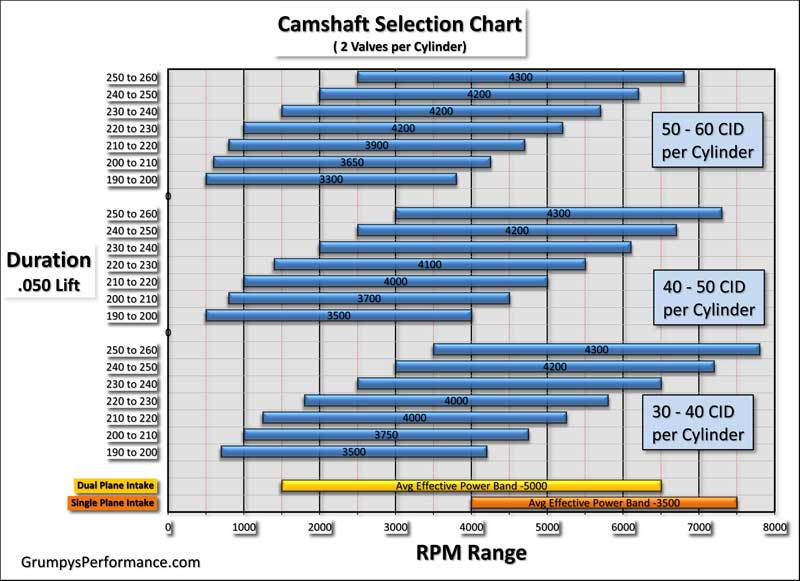
Interested to see what a simulation would show.
Rick as requested.

Dynomation 6 Input Variables

Bore & Stroke: 4.00 X 3.622 (LQ4)
Displacement: cubic inches: 364
Rod Length: 6.098
Heads Make/Model with flow numbers: Flow (CFM) at several lift points.
0.05031.124.7
0.10065.452.6
0.200142.298.1
0.300193.5133.5
0.400230.2160.1
0.500243.4175.5
0.600248.1185.8
0.650249.3188.2
0.700250.2191.1
Combustion Chamber Size in CC’s: 62
Dome Volume: For a domed piston use a (-) negative number. +6.7 (dished)
Valve Relief Volume: For a piston with valve reliefs or dish, use a (+) positive number. see above
Deck Clearance: (Piston to Block Surface) - not measured... assume 0.00"??
Head Gasket Bore: 4.06
Head Gasket Thickness: .040"
Valve Sizes Intake/Exhaust: 2.00/ 1.55
Intake Manifold Type: [Single or Dual Plane] - Dual
Manufacture/Model #: Edelbrock - RPM LS 71187
Carburetor Size or EFI (CFM): 770, vac secondary Holley
Blower/Turbo Make/Model: N/A
Belt Ratio: N/A
Header Tube Diameter: 1-5/8", 1-3/4", 1-7/8", 2.0" - 1 -7/8"
Cam Part Number: Elgin E-1840-P
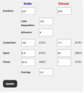
Cam Specs: Need all 8 valve timing events at seat-to-seat and at 0.050” plus lobe lift or valve lift OR post Cam Card OR give me what you have.
0.006" and 0.050"
1687062625697.png1687062678048.png
Rocker Ratio - Intake/Exhaust: 1.7
Cam Installed per Cam Card, or Retarded or Advanced: as per above, installed as per card with ground in 4 degree advance
Fuel Used: Gasoline (Octane ?), Methanol, Ethanol, E85 ..... gas 89 (mid grade where I live 87,89,91)
 
Here is your baseline graph and PDF report. Please look over the report and MAKE SURE I have all the numbers correct. There are lots of numbers when it comes to entering flow numbers and camshaft specs and can be entered wrong. They need to correct, because most everything going forward will be compared to them. A mistake here will throw everything off.

Sim01_Elgin_-E1840P.jpg

It would be helpful to know your deck height, I used .020". If this is close then your SCR/DCR are looking good. But your quench distance of .060" is abit too large. Ideal would be around. .040" and would help deter detonation. But until you know for sure the deck height, we are only guessing.

1687207013279.png
.
 

Attachments

  • Sim01__Elgin_ E1840P_Report_01.pdf
    174.5 KB · Views: 4
Rick

I think 0.020” is a bit far down in the hole. I calculated out the compression ratio to be closer to 10.3:1 from my measurements. I think that puts it 0.010” rather than 0.020” deck.

How does that change the numbers?

Either way I guess it all relative to a baseline.

I’ll send new cam specs once I find them again.

Thanks appreciate your help
Graham
 
Rick,

looking at this cam 0.006" and 0.050"
1687265275307.png1687265368350.png
Lift is maximum 0.601" on intake and 0.597"exhaust

Thanks
Graham
 

Attachments

  • 1687265356528.png
    1687265356528.png
    20.2 KB · Views: 1
I think 0.020” is a bit far down in the hole. I calculated out the compression ratio to be closer to 10.3:1 from my measurements. I think that puts it 0.010” rather than 0.020” deck.

How does that change the numbers?
Did you measure the deck clearance and how was it done ? I'm sorry, but at this point I don't know what your skill level is so I have to assume you don't know how things work at this time.

Engine #2 would possibly need 91 octane, but retarding the cam could bring it back inline with your goal of 89 octane. Are the heads cast iron or aluminum?

Engine #3 would need at least 93 octane or better, but again retarding the cam can help. But we need to know without guessing the deck clearance.

1687280806466.png

Did you review the report for accuracy?

Question ...... do these numbers already have 4° advance in them or do I have to add 4° advance to them?

1687283157225.png

Does the new camshaft have a Manufacture and PN ?

BTW, the compression ratio calculator can be downloaded at the link below on this website. It's the 6th link down on the page. You will need Microsoft Excel or Open Office that's free. This calculator can do up to 5 engines at one time.

.
 
Rick,

Ok, a bit of history. I was viewing the David Vizard calculation for LSA. I currently run the first cam you simulated.

The second cam would be a custom ground cam based off of the DV formula but I did not want the idle to get any worse than the current cam.

So... I looked at the current cam's 0.006 and 0.050 durations to see what cam specs would be required to run the same 0.006 overlap. I was wanting to see if the cam specs at same overlap with tighter LSA and shorter duration would still have the same power curves.

According to DV tighter LSA should pick up power down low AND up top if the right LSA is spec'd. This is kind of confirmed by some tests Richard Holdener did on 108,112,120 LSA. Where the 108 made better low torque and upper HP. BUT he did it with the same duration cam and only changed LSA... which affected idle.... I don't want that.

My question was kind of for DV knowledgeable people is can I run the shorter duration cam with tighter LSA and have the same or better power curve then the 112 spec'd cam?

My back ground is I'm a former mechanic and a mechanical engineer. I do know how to measure the deck height but did not do it... normal rush to get things done... It's not like I was going to change anything based on the results anyway... so I did not measure. I swapped the 71cc chamber heads for 799 LS heads that were surfaced to make sure they were flat but did not get LQ4 the block decked. All the specs are for a stock LQ4 which is supposed to have a 9.4:1 Comp ratio.

Based off of original specs... found on internet.

Based off of that the cylinder volume is (4^2/4*3.1415*3.622) = 45.51cuin divided by 8.4 =5.41 cuin chamber volume on a stock engine. (5.41+45.51)/5.41 = 9.4:1

The heads were swapped for the aluminum 799 heads that were surfaced. So, changing from 71CC heads to 62cc heads increases compression ratio from 9.4:1 to 10.36:1

5.41 * 2.54^3 = 88.65CC - 71CC + 62CC = 79.45cc (assuming same head gasket thickness, blab, blab, blab...)

79.65 CC / 2.54^3 = 4.86cuin

New Compression ratio = (4.86+45.51)/4.86 = 10.36:1

The cams are all ground with 0 advance but installed 4 degree advanced. The number right under the LSA (in the above screen shots) is the installed advance/retard. If the cams were ground 0 degree and installed 0 degree advance/retard the ICL and ECL would be the same as the LSA. Since the ICL and ECL are not the same as the LSA the cam is either ground at 0 advance and installed 4 degree advanced or ground 4 advanced then installed at 0 advance (same difference, cam events all happen 4 degree advanced either way).

Anyway, original question was does tightening LSA and shortening duration to keep Overlap the same, according to DV formula, make the same torque and HP and retain idle quality? or more torque/power or less?

Interesting point does the simulation confirm the 108,112,120 LSA test with same durations that Richard Holdener conducted?
 
RIck,

Sorry did not answer your question.
Oh yes, I looked through the details on the simulation very closely. It will be interesting to see if the BSFC changes with LSA at same power level... indicating a more or less efficient engine...

I'm not sure at what value the MEP starts to require premium pump fuel... Thats beyond my knowledge.

I love the numbers... engineer mind...

Thanks
Graham
 
My back ground is I'm a former mechanic and a mechanical engineer. I do know how to measure the deck height
Thanks for the background, mechanical engineer sounds familiar. Did you already mention it before in your other thread? Going forward I will know how to word my statements.

The second cam would be a custom ground cam based off of the DV formula but I did not want the idle to get any worse than the current cam.
OK, this cam will be call "Custom Cam #1" going forward then.

If the cams were ground 0 degree and installed 0 degree advance/retard the ICL and ECL would be the same as the LSA.
Yes, that's right. I should have noticed that!

Oh yes, I looked through the details on the simulation very closely. It will be interesting to see if the BSFC changes with LSA at same power level... indicating a more or less efficient engine...
Did you want a report for each simulation so you can watch these numbers?

I'm not sure at what value the MEP starts to require premium pump fuel... Thats beyond my knowledge.
That's what we typically use the DCR for, to determine what octane might be needed. Of course it's not a black-n-white situation.

I love the numbers... engineer mind...
I hear you, that's why I've done so many Excel spreadsheets for this website.

Where do we go from here? What else do want to see, I've got lots of camshaft files we can compare.

Sim01_ElginE1850P_vs_Sim02_CustomCam#1.jpg
 
Did you want a report for each simulation so you can watch these numbers?

That would be great to get eh numbers
 
No problem, it's easy to produce. See attachment.
.
 

Attachments

  • Sim02_Custom Cam #1_Repor_02t.pdf
    178.2 KB · Views: 4
Tried several cams and the Crower 00471 for the SBC Gen I, using this lobe profile gave some interesting results. I am using this cam in my TBucket (400 cuin). I should be able to provide a video with sound showing it's idle properties. You would have to check with Crower to see if they could grind it on your cam blank.

It does have 69° of overlap, 9° more than your goal and the lift is getting pretty high at .629/.634. Since IVC is 69° the DCR would essentially be the same as Engine #2 above at 7.96.

The Crower is better than the Elgin everywhere. It's also better than Custom Cam #1 above 4000 rpm.

But what do you think, that's what matters???

Sim01_vs_Sim02_vs_Sim03.jpg
Crower_HR_00471_555_560.JPG
.
 
Last edited:
yeah thats why I suggested that crower 00471 for your build RICK, I've tried dozens of cams over 45 plus years in 383-406 SBC combos and in similar engines to yours its a really an exceptional and useful compromise between drive ability and power
 
I would have to agree 100% Grumpy !!!

It's proved to be a handful at WOT in a 1900 lb car ! ;)
snoopy-happy-dance.jpg
 
Hey Gents,

Rick,

Thanks for the numbers. I looked through and the numbers and the Custom cam is more efficient (look at BFSC, low rpm 0.42X versus 0.43X) but about same efficiency on the on the top. (0.84X at max HP).

Power is also down a bit on the top.

This makes me think that the tighter LSA is a good thing, more efficient at lower RPM, but maybe need to look for something with a bit longer duration to not lose the top end... and hopefully a bit more efficient as well.

The Crower would be a great cam in a light vehicle but I think too much duration for 3800lbs... would need a pretty high stall and affect drivability.

I'm going to look at CompLobe catalog and see if I can increase duration on the same LSA and if you could run number that would be great.

Question if the customs cam above was ground on 108 LSA and still installed 4 degree advance (104 ICL, 112ECL), how would that compare to the 107 LSA custom cam? Wondering

Grumpy,

It appears you have a lot of experience. Have you ever installed tight LSA cams as per DV cam selection process? What kind of application? results?

Thanks
Graham
 
Rick,

Sorry the more information you give the more questions I have... LOL!!

Do you input ignition timing? What affect does changing timing do to the curves and numbers?

I might have to get this program just to have some fun... Like I said engineer... love the numbers...

Custom Cam #2 - increased duration. lift is 0.612" intake and 0.605" exhaust.

1687424252226.png1687424286683.png
 
tighter LSA tend to lope more noticeably and run noticeably rougher below about 2500 rpm-3500 rpm
(obviously the duration and compression and displacement all effect the power band)
but generally provide a noticeable boost in torque, they also tend to not pass emission testing as well in some applications
compr-psi.gif


46.jpg


LOBE SEPARATION ANGLE
Above 114 Deg. = Extremely Wide
114-112 Deg. = Wide
112-110 Deg. = Moderately Wide
110-108 Deg. = Moderate
108-106 Deg. = Moderately Tight
106-104 Deg. = Tight
Below 104 Deg. = Extremely Tight

VARYING LOBE SEPARATION ANGLE
Tighten.................................................Widen
Moves Torque to Lower RPM.................Raise Torque to Higher RPM
Increases Maximum Torque..................Reduces Maximum Torque
Narrow Power Band..............................Broadens Power Band
Builds Higher Cylinder Pressure............Reduce Maximum Cylinder Pressure
Increase Chance of Engine Knock.........Decrease Chance of Engine Knock.
Increase Cranking Compression...........Decrease Cranking Compression
Increase Effective Compression............Decrease Effective Compression
Idle Vacuum is Reduced........................Idle Vacuum is Increased
Idle Quality Suffers...............................Idle Quality Improves
Open Valve-Overlap Increases.............Open Valve-Overlap Decreases
Closed Valve-Overlap Increases...........Closed Valve-Overlap Decreases
Natural EGR Effect Increases................Natural EGR Effect is Reduced
Decreases Piston-to-Valve Clearance...Increases Piston-to-Valve Clearance
[color:red]LCA =(LOBE CENTER ANGLES)remember lobe center angles can be changed thru indexing the cam when degreeing it in[/color]
ADVANCING / RETARDING CAM TIMING

KEEP IN MIND MANY CAMS ARE FACTORY SET UP TO BE 4 DEGREES ADVANCED if INSTALLED DOT-TO-DOT

ADVANCING.
Begins Intake Event Sooner........................
Open Intake Valve Sooner..........................
Builds More Low-End Torque.......................
Decrease Piston-Intake Valve Clearance....
Increase Piston-Exhaust Valve Clearance...

RETARDING
Delays Intake Event Closes Intake
Keeps Intake Valve Open Later
Builds More High-End Power
Increase Piston-Intake Valve Clearance
Decrease Piston-Exhaust Valve Clearance
 
Last edited:
Grumpy,

I understand all of the above. I understand why DV wants the tight LSA, to gain low speed torque BUT he is also claiming that at the CORRECT LSA the top end doesn’t suffer. See Richard Holdener 108, 112, 120 camshaft test video. The 108 out performed the other cams everywhere.

Hence, my original question was my current cam 0.585/0.585, 283/286 at 112. According to above I should be able to find a tighter LSA cam that provides more torque but gives up nothing in top. Make sense?

I could just grind my current specs in a 107 LSA and potentially gain torque and HP, but idle will suffer. So I should be able to find a tighter LSA cam with different duration/overlap that give near same results as my 112 camshaft…. But what are those specs?

I determined from DV formula that LSA needs to be 107 BUT I don’t want to run 283/286 at that LSA because of the idle quality. I have no emissions testing.

Therefore my original question was (as I can’t find anything online after selecting LSA per DV) how to select overlap/duration. There was the guideline/ranges for different overlap per application, but since I already had a cam I’m happy with the idle….. how do I select overlap/duration.

Rick ran the numbers on a custom cam ( with same advertised overlap) and it picked up torque but lost HP on top. So I need to adjust the overlap/duration to gain more HP but not to lose too much torque. Does that make sense?

However any longer overlap/duration WILL affect idle…. So original question how do you spec overlap as per DV to gain torque and HP, or do I have to give up idle quality to do so…..

Clear as mud?
 
every choice you make is a compromise in several areas, unless you have VARIABLE valve timing, I think this chart may also help.
most people find selecting a cam using this info rather helpful if used with the previous info
btw you might want to look into there are variable valve timing rockers, if its really important

VARIABLE valve timing
In internal combustion engines, variable valve timing (VVT) is the process of altering the timing of a valve lift event, and is often used to improve performance, fuel economy or emissions. It is increasingly being used in combination with variable valve lift systems.


duration_v_rpm_range_wintakemanifold01_b2df3f98be614a599705bb1f0b557d37f1804ad2.jpg


Basically, it varies the valve timing by shifting the phase angle of camshafts. For example, at high speed, the inlet camshaft will be rotated in advance by 30° so to enable earlier intake. This movement is controlled by engine management system according to need, and actuated by hydraulic valve gears.
 
Back
Top