http://www.jegs.com/s/tech-articles/tor ... +Converter
http://auto.howstuffworks.com/auto-part ... erter2.htm
Runout - runout should be less than 0,25 mm (0,010 inch).
Balance - should be checked with the turbine in at least three positions. This insures that the converter will
not be internally out of balance. Overall balance should be held within 10 grams.
Internal Dimensional Standards:
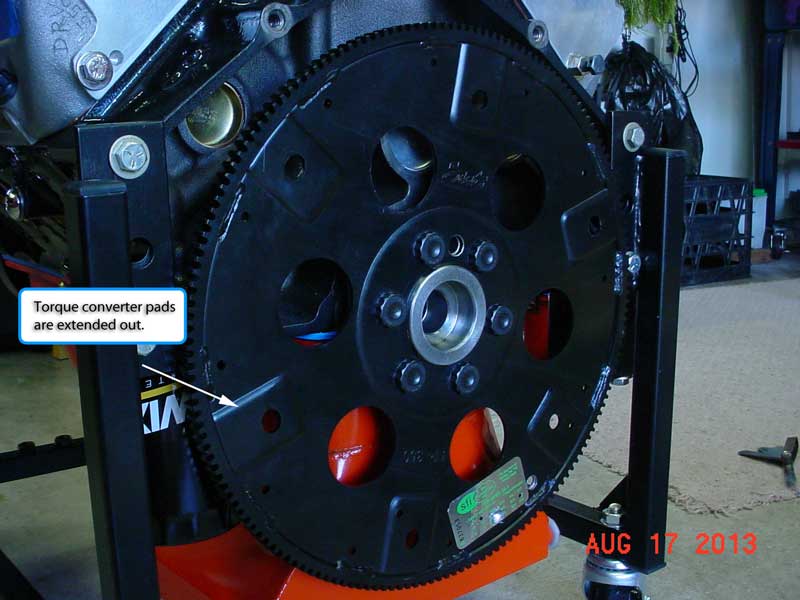
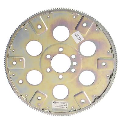
Turbo 400 uses the Big Bolt pattern torque converter.
11.5" inches bolt circle pattern.
4L80E uses same.
4L60E, 700R4, 200R4, & Turbo 350 uses the small bolt pattern torque converter.
10.75" inch bolt circle pattern.
Fit of pilot bushing - 0,10 mm-0,20 mm (0,004 inch - 0,008 inch) typical.
Rick
Torque Converter Knowledge Base
Common Torque Converter Questions and Answers
1. How Do I choose the converter stall speed that is right for my application?
Answer:� Advertised stall speed will need to be at least 500 RPM higher than the beginning of the powerband of your camshaft. All aftermarket camshafts are supplied with a cam card that states RPM range.� If your camshaft states an RPM range of 1500-6500, for example, you would want to select a torque with a minimum of 2,000 RPM stall.� For a street car it is wise to also select a torque converter stall speed that is below the engine RPM at 65 MPH to prevent excessive heat build up. The exception would be a transmission/converter equipped with lock-up.�
2. What is the difference in the terms "Flash Stall" and "Foot-Brake Stall"?
Answer: Of the two measurements of torque converter stall, 'Flash Stall' is the most accurate. Foot-Brake stall is dependant upon too many variables. (i.e. type of braking system, disc or drum brakes, how well adjusted the brake system is, ring and pinion ratios effect foot-brake stall more dramatically, idle characteristics of engine, cam installation for low end torque as needed by automatic transmission.)
Flash Stall can be determined a couple of different ways:
-With the vehicle sitting still and idling in low gear, apply full throttle. As the vehicle begins its motion forward, notice the RPM hand on the tachometer. That is your Flash Stall. (Engine should be very responsive from idle. If not, camshaft timing and/or carburetor adjustments may need to be made in order for engine to be crisp from idle.)
-With the vehicle in forward motion in high or drive gear and at its lowest mph where it will not kick back to a lower gear, apply full throttle while noticing rpm hand of tachometer. (This measurement of flash stall is best achieved with a full manual transmission.)
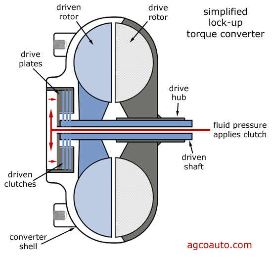
3. What does the term "Lock-Up" Torque Converter mean?
Answer: This term refers to a converter that contains an internal lock-up piston or device, either friction or mechanical. Transmissions such as TH350C, 2004R, 4L60 (700R4), 4L60E, 4L80E, AOD, AODE/4R70W and others, use these methods of eliminating slippage for an increase in fuel economy. Older transmissions such as the TH400, TH350, C6, C4 and others did not incorporate these methods of lock-up. The only way to increase fuel efficiency in these types of converters is to change clearances, redirect fin angles and usually lower the actual stall speed.
4. Should I replace the front seal and bushing in my transmission before installing the new TCI� torque converter I just purchased?
Answer: Yes. You should inspect the old torque converter you are removing for damage to the converter hub that rides in the pump of the transmission. If you find any wear on the hub at all, you should replace both seal and bushing. If you find no wear at all, you may be fine with just a seal replacement. You should at least do one (seal) if not both. (seal & bushing)
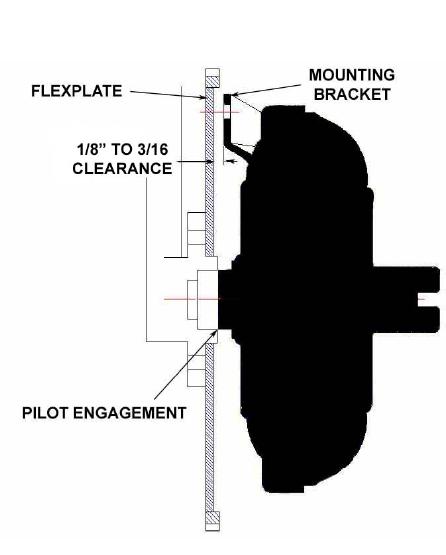
5. What type of clearance should I have between the torque converter and flexplate before pulling the converter forward and bolting it to flexplate?
Answer: You should have 1/8" (.125") to 3/16" (.1875") between the torque converter and flexplate before pulling the converter forward and bolting it to flexplate.
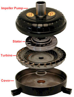
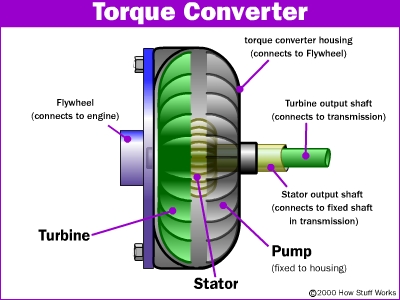
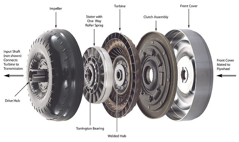
The torque converter consists of four primary components:
Cover --- the cover (also referred to as a front) is the outside half of the housing toward the engine side from the weld line. The cover serves to attach the converter to the flywheel (engine) and contain the fluid. While the torque converter cover is not actively involved in the characteristics of the performance, it is important that the cover remain rigid under stress (torsional and thrust stress and the tremendous hydraulic pressure generated by the torque converter internally.)
Turbine --- the converter turbine rides within the cover and is attached to the drive train via a spline fit to the input shaft of the transmission. When the turbine moves, the car moves.
Stator --- the stator can be described as the "brain" of the torque converter, although the stator is by no means the sole determiner of converter function and characteristics. The stator, which changes fluid flow between the turbine and pump, is what makes a torque converter a torque converter (multiplier) and not strictly a fluid coupler.
With the stator removed, however, it will retain none of its torque multiplying effect. In order for the stator to function properly the sprag must work as designed: (1) It must hold the stator perfectly still (locked in place) while the converter is still in stall mode (slow relative turbine speed to the impeller pump speed) and (2) allow the stator to spin with the rest of the converter after the turbine speed approaches the pump speed. This allows for more efficient and less restrictive fluid flow.
The sprag is a one-way mechanical clutch mounted on races and fits inside the stator while the inner race splines onto the stator support of the transmission. The torque multiplier effect means that a vehicle equipped with an automatic transmission and torque converter will output more torque to the drive wheels than the engine is actually producing. This occurs while the converter is in its "stall mode" (when the turbine is spinning considerably slower than the pump) and during vehicle acceleration. Torque multiplication rapidly decreases until it reaches a ratio of 1:1 (no torque increase over crankshaft torque.) A typical torque converter will have a torque multiplication ratio in the area of 2.5:1. The main point to remember is that all properly functioning torque converters do indeed multiply torque during initial acceleration. The more drastic the change in fluid path caused by the stator from its "natural" return path, the higher the torque multiplication ratio a given converter will have. Torque multiplication does not occur with a manual transmission clutch and pressure plate; hence the need for heavy flywheels, very high numerical gear ratios, and high launch rpm. A more detailed discussion of torque multiplication can get very confusing to the layman as high multiplication ratios can be easily considered the best choice when in fact more variables must be included in the decision. Remember, the ratio is still a factor of the engine torque in the relevant range of the torque converter stall speed, i.e.: a converter with a multiplication ratio of 2.5:1 that stalls 3000 rpm will produce 500 ft.-lbs. of torque at the instance of full throttle acceleration if its coupled to an engine producing 200 ft.-lbs. of torque at 3000 rpm. However, if this same engine produces 300 ft.-lbs. of torque at 4000 rpm, we would be better off with a converter that stalled 4000 rpm with only a 2.0:1 torque multiplication ratio, i.e.: 300 x 2.0 = 600 ft.-lbs. at initial acceleration. Of course it would be better yet to have a 2.5:1 ratio with the 4000 rpm in this example (provided his combination still allows the suspension to work and the tires don't spin.) This is just a brief overview as the actual scenarios are endless.
Impeller pump --- the impeller pump is the outside half of the converter on the transmission side of the weld line. Inside the impeller pump is a series of longitudinal fins, which, drive the fluid around its outside diameter into the turbine, since this component is welded to the cover, which is bolted to the flywheel. The size of the torque converter (and pump) and the number and shape of the fins all affect the characteristics of the converter. If long torque converter life is an objective, it is extremely important that the fins of the impeller pump are adequately reinforced against fatigue and the outside housing does not distort under stress.
Stall speed --- the rpm that a given torque converter (impeller) has to spin in order for it to overcome a given amount of load and begin moving the turbine. When referring to "how much stall will I get from this torque converter", it means how fast (rpm) must the torque converter spin to generate enough fluid force on the turbine to overcome the resting inertia of the vehicle at wide open throttle. Load originates from two places (1) From the torque imparted on the torque converter by the engine via the crankshaft. (This load varies over rpm, i.e. torque curve, and is directly affected by atmosphere, fuel and engine conditions.) (2) From inertia, the resistance of the vehicle to acceleration, which places a load on the torque converter through the drive train. This can be thought of as how difficult the drive train is to rotate with the vehicle at rest, and is affected by car weight, amount of gear reduction and tire size, ability of tire to stay adhered to ground and stiffness of chassis. (Does the car move as one entity or does it flex so much that not all the weight is transferred during initial motion?)
Note: While referring to the resistance of the vehicle to move while at rest, the torque converter's stall speed and much of its characteristics for a given application are also affected by the vehicle's resistance to accelerate relative to its rate of acceleration. This resistance has much to do with the rpm observed immediately after the vehicle starts moving, the amount of rpm drop observed during a gear change and the amount of slippage in the torque converter (turbine rpm relative to impeller pump rpm.) A discussion involving how resistance to acceleration affects a torque converter involves more theory than fact and must involve all the dozens of other variables that affect rpm and slippage. The primary thing we want to remember about torque converter stall speed is that a particular torque converter does not have a "preset from the factory" stall speed but rather its unique design will produce a certain range of stall speeds depending on the amount of load the torque converter is exposed to. This load comes from both the torque produced by the engine and the resistance of the vehicle to move from rest. The higher this combined load the higher stall we will observe from a particular torque converter, and conversely, the lower the load, the lower the stall speed. Naturally, if the engine is not at wide open throttle we will not expect to observe as high a stall speed as we would under a wide open throttle.
Another point concerning engine torque is that we are only concerned with what we'll call the "relevant range" of the engine torque curve when discussing initial stall speed. This means if our particular torque converter chosen has a design that should produce a stall speed in a range of say 2000 to 2600 rpm given the application then we would refer to this as the relevant range of our interest in the engine's torque curve for this particular torque converter. In other words, only the torque characteristics of the engine torque in this rpm range will affect the amount of stall speed we actually observe. If we are using a high horsepower/high rpm engine that does not make much torque before 3000 rpm, it does not matter that the engine makes excellent torque over 3000 rpm if we are trying to use the torque converter in this example because its relevant range is 2000-2600 rpm and we would expect to see poor stall (2000 rpm or less) due to the poor torque produced by the engine in this range. Choosing the correct application torque converter - The buyer of a performance torque converter normally has very specific "wants" to be filled, namely: They want to improve the performance of their vehicle. This can mean they may want the new torque converter to help the car run quicker, run faster, idle in gear better, leave from a stop harder, "chirp" the tires on the gear changes, or pull a steeper hill. The buyer may be looking for any or all of these performance improvements.
They want to improve the dependability of their vehicle meaning they want to get rid of existing drive train failures they are currently having with either OEM or competitors products such as short life (to what they perceive is a proper life), "trash" related transmission failures, overheating, hard part breakage, engine problems that they may believe is caused by torque converter and general unreliable performance. They may have been told by friends, salespeople, advertising, technical articles, etc. that their particular application needs to have a "stall" converter. This is particularly true of first time performance camshaft purchasers where the salesperson or the camshaft catalog will recommend a higher than stock stall speed torque converter.
Torque converters do not function in a void by themselves. The torque converter is an integral part of the total vehicle combination. While many vehicle combinations and applications are very similar and it may seem obvious what the best torque converter selection is, it is normally a wise step to take a look at the intended application and choose the best torque converter for the particular application. TCI� uses an application questionnaire to gather the pertinent information. TCI� technical salespeople also spend a large portion of their day reviewing specific customer applications and recommending torque converters for those applications. There is no "black magic" formula that the variables can be plugged into resulting in a definitive torque converter choice. Torque converter choices are made based on accumulated historical knowledge of performance in various applications and the use of all or several basic charts and ratios derived through this historical information. As with many other automotive performance parts, torque converter design and construction is a dynamic art and can not be patterned on the results of a "plug-in" formula or solely allowed to follow the historical applications. TCI� looks at torque converter technology as an on going process of continuous improvement.
Furnace brazed fins - greatly improves the strength characteristics of the fins. The furnace brazing causes the housing and fins to move and act integrally as one unit. This greatly reduces the amount of flex, which causes fins to bend and break. Also, the more rigid the fins stay while under pressure, the more consistent the behavior of the torque converter. Needle bearings - properly selected and installed bearings withstand more pressure and provide less internal drag (drag robs horsepower and increases heat) than can be achieved with OEM style thrust washers. Thrust washers also tend to flake off material adding to contamination in the system (the transmission/torque converter hydraulic system.) Service and time proven manufacturer - Ask for recommendations from leading car enthusiasts in your local area or check out what the racers are using.
Drivability concerns in choosing a torque converter - A performance torque converter should not compromise one aspect of car performance to achieve another. When investigating a converter purchase ask whether the particular torque converter being looked at may improve initial takeoff at the sacrifice of top end mph or other similar results, questions, etc. With the technology and product available today a buyer very seldom needs to sacrifice one area of performance to gain in another. However, without proper selection assistance or guidance (and with many under engineered products on the market today) it is unfortunate that many buyers end up with a product that does not best suit his needs or expectations. Too low a stall torque converter will not benefit the customer. If the user has an application which requires at least 3000 rpm stall and they purchase a 2000 to 2500 rpm stall range converter, it will normally not even give them the 2000 rpm stall. It will act very similar to the stock torque converter they just removed.why? Because the engine needs to operate in its optimum rpm range and since the chosen torque converter is below that range, it is not getting enough load from the crankshaft side to operate as designed. Symptoms include engine stalling when in gear at a stop, low stall speed, hesitation when going to full throttle, a "bog" when leaving from stop at wide open throttle. Too high a stall range torque converter will not benefit the customer. You will see this situation most often when the customer does not have sufficient gear ratio for the converter stall range or the engine is not capable of the appropriate rpm range (too small a duration camshaft, inadequate valve springs, too low compression, etc.) Symptoms include high "revs" to pull away from stop, "marshmallow" accelerator feel when driving at part throttle, transmission and possibly engine overheating, and a pronounced engine rev when nailing the throttle from a cruising speed.
http://www.jegs.com/c/Transmission_Stre ... 5/10002/-1
Article courtesy of TCI