If you fail to read thru the linked info youll miss a great deal of related info you may NEED
http://www.cranecams.com/?show=article&id=2
http://www.cranecams.com/?show=article&id=3
http://www.cranecams.com/?show=faq&id=1
http://www.nitemareperformance.150m.com/ZDDP.html
http://circletrack.automotive.com/10913 ... index.html
READ THE LINKS
viewtopic.php?f=54&t=4793&p=13024#p13024
viewtopic.php?f=54&t=2102
viewtopic.php?f=54&t=1334
viewtopic.php?f=54&t=1334&p=2910#p2910
viewtopic.php?f=52&t=282
viewtopic.php?f=52&t=2166&p=5840&hilit=bore+groove#p5840
http://www.pbmperformance.com/store.php?catId=420
http://www.hotrod.com/techarticles/engi ... index.html
http://www.2quicknovas.com/happycams.html
http://www.iskycams.com/camshaft.php
http://shbox.com/ci/cam_removal.html
http://www.performanceresearchinc.com/p ... ducts.html
http://shbox.com/ci/cam_install.html
http://www.reedcams.com/degreeing.htm
http://www.ntnoa.org/enginebreakin.htm
http://www.digitalcorvettes.com/forums/ ... hp?t=80815
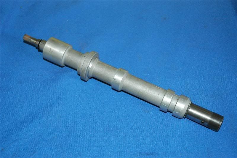
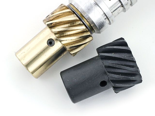
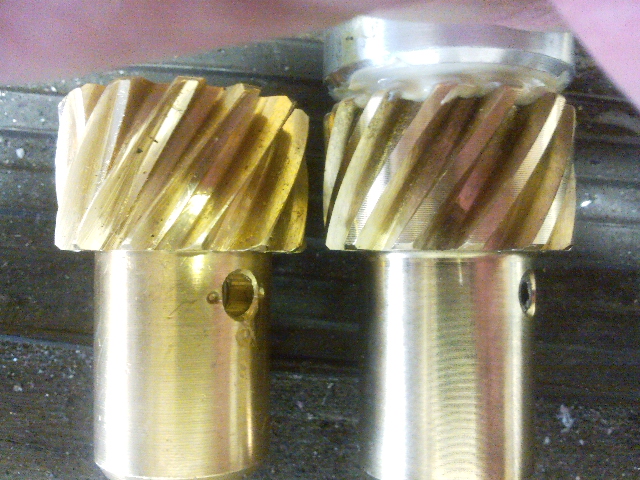
notice the approximate location and relationship between the cam pin and crank key

you may want to keep in mind that theres a huge variation in the quality of the metal and machine work in both the surface finish and hardening or rockwell numbers between different manufacturers and some of the cheaper imported lifters and cams are much softer and more prone to wear than the better brand name components, contrary to what you may think theres some advantage in paying for brand name vs bargain basement components, manufacturers LIKE, ERSON, LUNATI CRANE OR CROWER, have, standard, or premium lifters available with micro- polished surfaces and hardened components, and in some cases hardened cams and premium cores for an additional charge, over the cost of the base line products , but even those base products tend to be superior to many imports
Cam Break-in Procedure
• Have a high quality service manual available, such as the factory service manual, or the vehicle specific manuals published by Chiltons, Motors, or Haynes. You will need these for the basic information regarding engine disassemble and reassemble along with the torque settings for the various fasteners.
• Read and understand the manual completely, along with these instructions before you begin working. We highly recommend you also have the assistance of a knowledgeable friend to assist you, especially during the initial fire-up and break-in period.
In addition to the normal installation procedure, installing a performance camshaft requires you to check for several extra items to insure long life and optimum performance.
• New Lifters Are A Must- There is no such thing as a good used lifter! Any flat faced lifter establishes a wear pattern almost immediately with the cam lobe it is riding on and cannot be used on any other cam lobe, let alone a different cam. Should you have a need to disassemble the engine, make sure you keep the lifters in order so they go back on to the exact same lobes.
• Valve Spring Pressure and Travel- We highly recommend purchasing the matching valve springs recommended in our catalog. This insures you will have the proper pressures, both closed and open, and sufficient travel to get the maximum rpm, performance and life from your new cam.
• Piston to Valve Clearance- While many performance cams will work just fine with stock pistons, there are many factors that effect your engine and the clearance available. Things such as factory tolerances, normal machine work such as head and block surfacing, aftermarket components such as cylinder heads, higher ratio rocker arms, etc. all effect your engines ability to handle a performance camshaft.
• Valve Train Interference- In addition to valve spring travel and piston-to-valve clearance, a commonly overlooked area is that of retainer to seal clearance. The other common area of interference is rocker arm to stud clearance along with rocker arm travel. The best way to check these is by physically opening both a intake and an exhaust valve on each cylinder head to the gross lift of the cam plus and additional .030". It is easiest to do this by pressing down on the rocker arm with one of the many tools available. Do not simply rotate the engine to the maximum lift point for a given valve. This does not work when engines are hydraulic lifter equipped, or even allow any margin of safety when you are using a mechanical lifter cam.
• Valve Adjustment- The easiest way to insure proper adjustment is to adjust the rocker arms as you install them, one cylinder at a time. Adjust the intake valve as the exhaust valve is just starting to open and adjust the exhaust valve when the intake valve is almost closed. It is simplest to do this with the intake manifold off and watching the lifter’s movement.
• Hydraulic Lifter Valve Adjustment- All engines, regardless of manufacture, require correct valve adjustment. Some engines, such as Chevrolet V-8’s, are equipped with stud mounted rocker arms can easily be adjusted to compensate for changes incurred during engine assembly. Never just torque the rocker arm into place and assume that the lifter preload will automatically be correct. Various engine manufacturers use multiple length pushrods, shims, and spacers to compensate for changes in preload. Hydraulic lifters cannot compensate for all changes. Ideal lifter preload is .020" to .080". Do not attempt to fill the lifters full of oil prior to installation. They will fill automatically once started and manually filling them makes adjusting the preload a difficult task.
• Mechanical Lifter Valve Adjustment- Adjusting mechanical lifters should be done the same way as outlined above, one valve at a time. For an initial setting, we recommend .003" to .005" than listed on the cam’s specification card. Once broken in and with the engine fully warmed up, re set the rocker arms to the cam’s specification sheet.
• Installation Lubricants- All flat faced (non-roller) camshafts require the use of high pressure lubricant supplied with your Erson cam on the bottom of the lifters, the lobes of the cam and on the distributor drive gear. Do not use this lube on the tips of the pushrods, the sides of the lifters or on the rocker arms. Use a quality oil when installing roller tappets.
BEFORE YOU TURN THE KEY
• Fill All of the Engine’s Fluids- Using a minimum of a SAE API SD, SE or better fresh clean mineral based oil, fill the engine to the proper level. Do not use synthetic oil during break-in. Fill the coolant system and follow the instructions on purging air from the system. With carburetor equipped engines, fill the carburetor to insure fuel is available immediately. Make sure that the ignition timing is properly set to insure immediate starting, without excess cranking of the engine.
• Pre-Lube the Engine- Using a oil pump priming tool such as those available from Mallory, spin the engine’s oil pump until you see pressure on the gauge or have oil at the rocker arms. Do not attempt to prime the engine using the starter motor!
• Proper Ventilation- Make sure that you do not start the engine without good airflow. That means have the overhead garage door open and the exhaust vented to the outside. If you have any doubts about sufficient airflow to the engine, push the car out of the garage to make sure the radiator can draw in plenty of air. Having a fan to blow fresh air through the garage is a plus.
• Exhaust System- If at all possible, start the car with a muffled exhaust system hooked up and operational. It makes it much easier to hear what is going on.
• Resist the Urge- Take a minute before you try to start the engine for the first time and double check that you are ready to go. Don’t take any short cuts or leave parts such as fan shrouds, air cleaner, wire looms, etc. off. Clean up the are around and especially under your vehicle. Pick up your tools and wipe up the floor so you can easily spot even a minor leak.
• Be Prepared- Have extra coolant or a hose handy, clean rags, tools for tightening clamps, connections, etc. just in case. They need to be in place to make sure you have an uneventful break-in of the camshaft.
WHEN THE ENGINE STARTS
• Have a Helper- Now is the time for a helper. They can check the coolant level, check for oil and fluid leaks, and proper operation of underhood accessories. Air pockets in the coolant system are common so make sure the recovery bottle is checked and filled as necessary. You cannot count on the temperature gauge. Temperature gauges are only accurate if the sensor is submerged in coolant and will not give an accurate reading if in an air pocket.
• Do Not Idle the Engine- As soon as the engine starts, raise the rpm to 2,000 rpm. You should also constantly vary the RPM between 2,000 and 3,000 RPM for the first 20 minutes. This is the only way to insure proper lubrication during this critical period since the camshaft to lifter contact area relies almost exclusively on oil splash from the crank and connecting rods. Make sure that you run the engine for a full 20 minutes using this procedure. It will seem like forever, but it is one of the most important steps to insure long, dependable performance.
Once Break-in is Complete- Drain and replace the engine oil and filter with new, fresh oil and a new filter. Recheck for any fluid leaks and check all fluid levels. If you installed a mechanical lifter style camshaft, flat faced or roller style, the valve adjustment should be rechecked at this time with the engine fully warmed up. Hydraulic lifter equipped engines should not require any readjustment.
Proper maintenance is important for any vehicle. Frequent oil changes, with a new filter is one of the easiest ways to insure your vehicle will deliver the performance you want for many long happy miles.
ID ADD, USE a GOOD MOLY BASE ASSEMBLY LUBE AND A HIGH ZINC CONTENT OIL AND SOME G.M. E.O.S. TO THE OIL
http://www.crower.com/misc/product/dl/ZDDP_clr.pdf
moly cam lobe and some zddp helps
Break-In Tips
With a freshly rebuilt engine, the first 10-20 minutes of its life are probably the most important. During break-in, the piston rings seat against the cylinder walls, and the cam and lifters establish their life-long wear pattern. The day that you actually start the engine for the first time, have a few buddies help out during the break-in. As soon as the engine fires, have one buddy concentrate on actuating the throttle to keep it at a steady rpm--about 2,000 rpm. Then, use a timing light to set (or double-check) the ignition timing. Have one buddy stand back and monitor the entire break-in process. If oil or fuel begin to leak, or if smoke begins to develop, your "spotter buddy" can alert you to potentially bad developments so they can be immediately remedied.
run a garden hose thru the radiator fins, and use a fan blowing on the radiator to keep the coolant temps low, and be sure the coolant and oil levels are correct before you start,
After the engine has run for about 10 minutes, begin varying the engine speed between 1,500-4,000 rpm for about five-ten minutes. Afterward, determine if the engine will idle on its own. If not, timing and/or carburetor adjustments may be needed.
Once the engine receives about 30 minutes of break-in time, shut it off, and let it cool for a few hours. Drain the engine oil that will likely be contaminated with assembly lube and microscopic bits of metal worn off during the break-in process. Pour in new engine oil, and install a new oil filter. Once the cylinder heads have cooled, pull the spark plugs one at a time to determine their operating condition--lean, fuel fouled, oil fouled and so on. Be sure to check the condition of the spark plug wires, making sure that none have been burnt during engine break-in.
Finally, carefully inspect the entire engine checking for oil, fuel or coolant leaks that may have developed. Oftentimes, after the engine has heated up during break-in, various bolts will loosen up slightly--especially exhaust header and intake manifold bolts.
these instructions were included with a rebuilt engine
Break-in and Installation Instructions
PROTECT THE INVESTMENT YOU HAVE IN YOUR ENGINE.
TAKE THE TIME TO READ AND FOLLOW THESE RECOMMENDATIONS:
BREAK IN PROCEDURE
1.) Drive normally but not a continuous high speeds for the first 500 miles. Occasional quick bursts of speed followed by quick deceleration during this period, is beneficial. AVOID LUGGING!!! TRIPS AND TOWING are not recommended until after 1000 miles.
NOTE:
Applying loads to the engine for short periods of time causes increased ring pressure against cylinder walls and helps to seat the rings. This is especially important because you are "BREAKING-IN" the engine with heavy duty oils. The rapid deceleration increases vacuum and gives extra lubrication to the piston and other assemblies.
2.) IMPORTANT! AFTER 500 TO A MAXIMUM OF 1000 MILES OF SERVICE, change oil and filter and readjust the valves, except hydraulic. We also require that valve adjustments be done again after a total of 6000 miles. We require a maximum of 3000 miles between oil changes and factory recommendation on valve adjustments thereafter.
NOTE:
Add oil at 1/2 quart intervals on small capacity engines. OIL AND WATER LEVELS ARE A DRIVER OR OWNER MAINTENANCE RESPONSIBILITY, THEY MUST BE KEPT FULL. We realize that this means extra effort on your part, but it assures long and satisfactory engine performance.
3.) A heavy duty detergent oil is required. Use a good quality brand oil, Some Manufacturers require 5/30, others recommend 10/40 for 20 degrees Fahrenheit to 100 degrees Fahrenheit and use 20/50w for higher temperatures and heavy duty use.
NOTE:
In past years, it has been common practice to use non-detergent and straight weight oil during the "BREAK-IN" period because it was felt that the rings would seat quicker without the film strength additives. More recently, there has been a trend to high speed and high temperature engines, cam lobe and tappet loads also have increased to a point where it is important to use heavy duty oils which contain a EP (high pressure) additive right from the start. Rings will seat properly when moderate loads are applied as noted above in section one.
4.) Keep your engine in tune. Tune-up specifications should always be to the manufacturers recommended specifications.
5.) PLEASE! If you experience any trouble or even suspect a problem please contact us IMMEDIATELY! It is easier and cheaper to fix a little problem than a big one.
IMPORTANT ITEMS TO LOOK FOR WHEN INSTALLING
A REPLACEMENT ENGINE TO AVOID EARLY ENGINE FAILURE
1.) Determine why old engine failed. Check catalytic converter or computer controlled parts, check engine warning light codes, radiator, water pump, etc. Do not install replacement engine with defective components, this could cause premature failure.
2.) Compare rebuilt engine with old engine as to crankshaft flange, pilot hole and bearing, oil pan, timing cover, engine mounting provisions and cylinder head mounting holes.
3.) Prime the oil pump in any acceptable Industry Standard Method! This is very important.
4.) All related parts not furnished by us should be thoroughly cleaned.
5.) If original engine has blown and scattered pieces, such as piston particles, you Must thoroughly inspect intake manifold for foreign material to avoid destroying the new engine.
6.) Make sure that dipstick tube and dipstick are of proper length to register required amount of oil.
7.) Check motor mounts for oil soak and parting of rubber from metal.
8.) Radiator should be flow tested and thoroughly cleaned if necessary.
9.) Check radiator cap for application and operation.
10.) Replace thermostat to avoid possible failure.
11.) All hoses, radiator, heater, and by pass should be replaced if necessary.
12.) A heavy duty detergent oil is required. Use a good quality brand oil, Some Manufacturers require 5/30, others recommend 10/40 for 20 degrees Fahrenheit to 100 degrees Fahrenheit and use 20/50w for higher temperatures and heavy duty use.
13.) Always replace oil filter cartridge and flush any cooler lines. And replace oil cooler if contaminated.
14.) Oil pressure and temperature sending units may need to be replaced because they have a tendency to leak oil and register improper after a reinstall.
15.) Always install new spark plugs of proper heat range and check to make sure the spark plug wires are in good condition.
16.) Check distributor, advance controls and distributor cap for cracks.
17.) Water pump should be checked for signs of leaking.
18.) Clutch fan should be checked for proper operation.
19.) Fan belts should be checked for cracks and other defects.
20.) Check fuel pump for oil leak at pivot pin and also for fuel leaks.
21.) Check heat riser valve for proper operation.
22.) Replace paper air filter or clean oil type.
23.) Check smog components and computer sensors. Replace defective or old parts.
24.) VERY IMPORTANT!!!
Make sure radiator is full of coolant (at least 50% water and 50% antifreeze) and Engine Block is filled full before attempting to start engine.
CAUTION: Air Locks can ruin a new engine.
25.) When filling radiator make sure it is filled to proper capacity and that there are no air locks, as this can cause cracking of cylinder block and heads.
26.) Start engine, check oil pressure, adjust ignition timing to manufacturers specifications and adjust carburetor after engine has warmed up fully. Also, at this time be sure to check for any water or oil leaks.
27.) Take the car for a road test. After road testing the vehicle recheck installation, oil and water levels, look for any leaks, recheck timing and adjust carburetor if necessary. Please refer to "BREAK IN PROCEDURE" sheet for further information.
See Warranty Addendum #8
NOTE: After at least 1 hour running time and engine has cooled, retorque head and adjust valves to manufacturers specifications. On Required engines if you are not sure if this is required on your engine ASK!
ATTENTION: WARNING TO INSTALLING MECHANIC!!!
Every effort has been made to accurately supply the proper item, however it is the responsibility of the installing mechanic to verify engine and parts for correct size and application by comparing the old parts. This is due to the many combinations available on the market today. You are responsible for the correct installation of the engine. The engine life and performance depends on a good professional installation. Follow the instructions carefully. Seek professional help if you are uncertain about ANYTHING!
http://www.cranecams.com/?show=article&id=2
http://www.cranecams.com/?show=article&id=3
http://www.cranecams.com/?show=faq&id=1
http://www.nitemareperformance.150m.com/ZDDP.html
http://circletrack.automotive.com/10913 ... index.html
READ THE LINKS
viewtopic.php?f=54&t=4793&p=13024#p13024
viewtopic.php?f=54&t=2102
viewtopic.php?f=54&t=1334
viewtopic.php?f=54&t=1334&p=2910#p2910
viewtopic.php?f=52&t=282
viewtopic.php?f=52&t=2166&p=5840&hilit=bore+groove#p5840
http://www.pbmperformance.com/store.php?catId=420
http://www.hotrod.com/techarticles/engi ... index.html
http://www.2quicknovas.com/happycams.html
http://www.iskycams.com/camshaft.php
http://shbox.com/ci/cam_removal.html
http://www.performanceresearchinc.com/p ... ducts.html
http://shbox.com/ci/cam_install.html
http://www.reedcams.com/degreeing.htm
http://www.ntnoa.org/enginebreakin.htm
http://www.digitalcorvettes.com/forums/ ... hp?t=80815
notice the approximate location and relationship between the cam pin and crank key
you may want to keep in mind that theres a huge variation in the quality of the metal and machine work in both the surface finish and hardening or rockwell numbers between different manufacturers and some of the cheaper imported lifters and cams are much softer and more prone to wear than the better brand name components, contrary to what you may think theres some advantage in paying for brand name vs bargain basement components, manufacturers LIKE, ERSON, LUNATI CRANE OR CROWER, have, standard, or premium lifters available with micro- polished surfaces and hardened components, and in some cases hardened cams and premium cores for an additional charge, over the cost of the base line products , but even those base products tend to be superior to many imports
Cam Break-in Procedure
• Have a high quality service manual available, such as the factory service manual, or the vehicle specific manuals published by Chiltons, Motors, or Haynes. You will need these for the basic information regarding engine disassemble and reassemble along with the torque settings for the various fasteners.
• Read and understand the manual completely, along with these instructions before you begin working. We highly recommend you also have the assistance of a knowledgeable friend to assist you, especially during the initial fire-up and break-in period.
In addition to the normal installation procedure, installing a performance camshaft requires you to check for several extra items to insure long life and optimum performance.
• New Lifters Are A Must- There is no such thing as a good used lifter! Any flat faced lifter establishes a wear pattern almost immediately with the cam lobe it is riding on and cannot be used on any other cam lobe, let alone a different cam. Should you have a need to disassemble the engine, make sure you keep the lifters in order so they go back on to the exact same lobes.
• Valve Spring Pressure and Travel- We highly recommend purchasing the matching valve springs recommended in our catalog. This insures you will have the proper pressures, both closed and open, and sufficient travel to get the maximum rpm, performance and life from your new cam.
• Piston to Valve Clearance- While many performance cams will work just fine with stock pistons, there are many factors that effect your engine and the clearance available. Things such as factory tolerances, normal machine work such as head and block surfacing, aftermarket components such as cylinder heads, higher ratio rocker arms, etc. all effect your engines ability to handle a performance camshaft.
• Valve Train Interference- In addition to valve spring travel and piston-to-valve clearance, a commonly overlooked area is that of retainer to seal clearance. The other common area of interference is rocker arm to stud clearance along with rocker arm travel. The best way to check these is by physically opening both a intake and an exhaust valve on each cylinder head to the gross lift of the cam plus and additional .030". It is easiest to do this by pressing down on the rocker arm with one of the many tools available. Do not simply rotate the engine to the maximum lift point for a given valve. This does not work when engines are hydraulic lifter equipped, or even allow any margin of safety when you are using a mechanical lifter cam.
• Valve Adjustment- The easiest way to insure proper adjustment is to adjust the rocker arms as you install them, one cylinder at a time. Adjust the intake valve as the exhaust valve is just starting to open and adjust the exhaust valve when the intake valve is almost closed. It is simplest to do this with the intake manifold off and watching the lifter’s movement.
• Hydraulic Lifter Valve Adjustment- All engines, regardless of manufacture, require correct valve adjustment. Some engines, such as Chevrolet V-8’s, are equipped with stud mounted rocker arms can easily be adjusted to compensate for changes incurred during engine assembly. Never just torque the rocker arm into place and assume that the lifter preload will automatically be correct. Various engine manufacturers use multiple length pushrods, shims, and spacers to compensate for changes in preload. Hydraulic lifters cannot compensate for all changes. Ideal lifter preload is .020" to .080". Do not attempt to fill the lifters full of oil prior to installation. They will fill automatically once started and manually filling them makes adjusting the preload a difficult task.
• Mechanical Lifter Valve Adjustment- Adjusting mechanical lifters should be done the same way as outlined above, one valve at a time. For an initial setting, we recommend .003" to .005" than listed on the cam’s specification card. Once broken in and with the engine fully warmed up, re set the rocker arms to the cam’s specification sheet.
• Installation Lubricants- All flat faced (non-roller) camshafts require the use of high pressure lubricant supplied with your Erson cam on the bottom of the lifters, the lobes of the cam and on the distributor drive gear. Do not use this lube on the tips of the pushrods, the sides of the lifters or on the rocker arms. Use a quality oil when installing roller tappets.
BEFORE YOU TURN THE KEY
• Fill All of the Engine’s Fluids- Using a minimum of a SAE API SD, SE or better fresh clean mineral based oil, fill the engine to the proper level. Do not use synthetic oil during break-in. Fill the coolant system and follow the instructions on purging air from the system. With carburetor equipped engines, fill the carburetor to insure fuel is available immediately. Make sure that the ignition timing is properly set to insure immediate starting, without excess cranking of the engine.
• Pre-Lube the Engine- Using a oil pump priming tool such as those available from Mallory, spin the engine’s oil pump until you see pressure on the gauge or have oil at the rocker arms. Do not attempt to prime the engine using the starter motor!
• Proper Ventilation- Make sure that you do not start the engine without good airflow. That means have the overhead garage door open and the exhaust vented to the outside. If you have any doubts about sufficient airflow to the engine, push the car out of the garage to make sure the radiator can draw in plenty of air. Having a fan to blow fresh air through the garage is a plus.
• Exhaust System- If at all possible, start the car with a muffled exhaust system hooked up and operational. It makes it much easier to hear what is going on.
• Resist the Urge- Take a minute before you try to start the engine for the first time and double check that you are ready to go. Don’t take any short cuts or leave parts such as fan shrouds, air cleaner, wire looms, etc. off. Clean up the are around and especially under your vehicle. Pick up your tools and wipe up the floor so you can easily spot even a minor leak.
• Be Prepared- Have extra coolant or a hose handy, clean rags, tools for tightening clamps, connections, etc. just in case. They need to be in place to make sure you have an uneventful break-in of the camshaft.
WHEN THE ENGINE STARTS
• Have a Helper- Now is the time for a helper. They can check the coolant level, check for oil and fluid leaks, and proper operation of underhood accessories. Air pockets in the coolant system are common so make sure the recovery bottle is checked and filled as necessary. You cannot count on the temperature gauge. Temperature gauges are only accurate if the sensor is submerged in coolant and will not give an accurate reading if in an air pocket.
• Do Not Idle the Engine- As soon as the engine starts, raise the rpm to 2,000 rpm. You should also constantly vary the RPM between 2,000 and 3,000 RPM for the first 20 minutes. This is the only way to insure proper lubrication during this critical period since the camshaft to lifter contact area relies almost exclusively on oil splash from the crank and connecting rods. Make sure that you run the engine for a full 20 minutes using this procedure. It will seem like forever, but it is one of the most important steps to insure long, dependable performance.
Once Break-in is Complete- Drain and replace the engine oil and filter with new, fresh oil and a new filter. Recheck for any fluid leaks and check all fluid levels. If you installed a mechanical lifter style camshaft, flat faced or roller style, the valve adjustment should be rechecked at this time with the engine fully warmed up. Hydraulic lifter equipped engines should not require any readjustment.
Proper maintenance is important for any vehicle. Frequent oil changes, with a new filter is one of the easiest ways to insure your vehicle will deliver the performance you want for many long happy miles.
ID ADD, USE a GOOD MOLY BASE ASSEMBLY LUBE AND A HIGH ZINC CONTENT OIL AND SOME G.M. E.O.S. TO THE OIL
http://www.crower.com/misc/product/dl/ZDDP_clr.pdf
moly cam lobe and some zddp helps
Break-In Tips
With a freshly rebuilt engine, the first 10-20 minutes of its life are probably the most important. During break-in, the piston rings seat against the cylinder walls, and the cam and lifters establish their life-long wear pattern. The day that you actually start the engine for the first time, have a few buddies help out during the break-in. As soon as the engine fires, have one buddy concentrate on actuating the throttle to keep it at a steady rpm--about 2,000 rpm. Then, use a timing light to set (or double-check) the ignition timing. Have one buddy stand back and monitor the entire break-in process. If oil or fuel begin to leak, or if smoke begins to develop, your "spotter buddy" can alert you to potentially bad developments so they can be immediately remedied.
run a garden hose thru the radiator fins, and use a fan blowing on the radiator to keep the coolant temps low, and be sure the coolant and oil levels are correct before you start,
After the engine has run for about 10 minutes, begin varying the engine speed between 1,500-4,000 rpm for about five-ten minutes. Afterward, determine if the engine will idle on its own. If not, timing and/or carburetor adjustments may be needed.
Once the engine receives about 30 minutes of break-in time, shut it off, and let it cool for a few hours. Drain the engine oil that will likely be contaminated with assembly lube and microscopic bits of metal worn off during the break-in process. Pour in new engine oil, and install a new oil filter. Once the cylinder heads have cooled, pull the spark plugs one at a time to determine their operating condition--lean, fuel fouled, oil fouled and so on. Be sure to check the condition of the spark plug wires, making sure that none have been burnt during engine break-in.
Finally, carefully inspect the entire engine checking for oil, fuel or coolant leaks that may have developed. Oftentimes, after the engine has heated up during break-in, various bolts will loosen up slightly--especially exhaust header and intake manifold bolts.
these instructions were included with a rebuilt engine
Break-in and Installation Instructions
PROTECT THE INVESTMENT YOU HAVE IN YOUR ENGINE.
TAKE THE TIME TO READ AND FOLLOW THESE RECOMMENDATIONS:
BREAK IN PROCEDURE
1.) Drive normally but not a continuous high speeds for the first 500 miles. Occasional quick bursts of speed followed by quick deceleration during this period, is beneficial. AVOID LUGGING!!! TRIPS AND TOWING are not recommended until after 1000 miles.
NOTE:
Applying loads to the engine for short periods of time causes increased ring pressure against cylinder walls and helps to seat the rings. This is especially important because you are "BREAKING-IN" the engine with heavy duty oils. The rapid deceleration increases vacuum and gives extra lubrication to the piston and other assemblies.
2.) IMPORTANT! AFTER 500 TO A MAXIMUM OF 1000 MILES OF SERVICE, change oil and filter and readjust the valves, except hydraulic. We also require that valve adjustments be done again after a total of 6000 miles. We require a maximum of 3000 miles between oil changes and factory recommendation on valve adjustments thereafter.
NOTE:
Add oil at 1/2 quart intervals on small capacity engines. OIL AND WATER LEVELS ARE A DRIVER OR OWNER MAINTENANCE RESPONSIBILITY, THEY MUST BE KEPT FULL. We realize that this means extra effort on your part, but it assures long and satisfactory engine performance.
3.) A heavy duty detergent oil is required. Use a good quality brand oil, Some Manufacturers require 5/30, others recommend 10/40 for 20 degrees Fahrenheit to 100 degrees Fahrenheit and use 20/50w for higher temperatures and heavy duty use.
NOTE:
In past years, it has been common practice to use non-detergent and straight weight oil during the "BREAK-IN" period because it was felt that the rings would seat quicker without the film strength additives. More recently, there has been a trend to high speed and high temperature engines, cam lobe and tappet loads also have increased to a point where it is important to use heavy duty oils which contain a EP (high pressure) additive right from the start. Rings will seat properly when moderate loads are applied as noted above in section one.
4.) Keep your engine in tune. Tune-up specifications should always be to the manufacturers recommended specifications.
5.) PLEASE! If you experience any trouble or even suspect a problem please contact us IMMEDIATELY! It is easier and cheaper to fix a little problem than a big one.
IMPORTANT ITEMS TO LOOK FOR WHEN INSTALLING
A REPLACEMENT ENGINE TO AVOID EARLY ENGINE FAILURE
1.) Determine why old engine failed. Check catalytic converter or computer controlled parts, check engine warning light codes, radiator, water pump, etc. Do not install replacement engine with defective components, this could cause premature failure.
2.) Compare rebuilt engine with old engine as to crankshaft flange, pilot hole and bearing, oil pan, timing cover, engine mounting provisions and cylinder head mounting holes.
3.) Prime the oil pump in any acceptable Industry Standard Method! This is very important.
4.) All related parts not furnished by us should be thoroughly cleaned.
5.) If original engine has blown and scattered pieces, such as piston particles, you Must thoroughly inspect intake manifold for foreign material to avoid destroying the new engine.
6.) Make sure that dipstick tube and dipstick are of proper length to register required amount of oil.
7.) Check motor mounts for oil soak and parting of rubber from metal.
8.) Radiator should be flow tested and thoroughly cleaned if necessary.
9.) Check radiator cap for application and operation.
10.) Replace thermostat to avoid possible failure.
11.) All hoses, radiator, heater, and by pass should be replaced if necessary.
12.) A heavy duty detergent oil is required. Use a good quality brand oil, Some Manufacturers require 5/30, others recommend 10/40 for 20 degrees Fahrenheit to 100 degrees Fahrenheit and use 20/50w for higher temperatures and heavy duty use.
13.) Always replace oil filter cartridge and flush any cooler lines. And replace oil cooler if contaminated.
14.) Oil pressure and temperature sending units may need to be replaced because they have a tendency to leak oil and register improper after a reinstall.
15.) Always install new spark plugs of proper heat range and check to make sure the spark plug wires are in good condition.
16.) Check distributor, advance controls and distributor cap for cracks.
17.) Water pump should be checked for signs of leaking.
18.) Clutch fan should be checked for proper operation.
19.) Fan belts should be checked for cracks and other defects.
20.) Check fuel pump for oil leak at pivot pin and also for fuel leaks.
21.) Check heat riser valve for proper operation.
22.) Replace paper air filter or clean oil type.
23.) Check smog components and computer sensors. Replace defective or old parts.
24.) VERY IMPORTANT!!!
Make sure radiator is full of coolant (at least 50% water and 50% antifreeze) and Engine Block is filled full before attempting to start engine.
CAUTION: Air Locks can ruin a new engine.
25.) When filling radiator make sure it is filled to proper capacity and that there are no air locks, as this can cause cracking of cylinder block and heads.
26.) Start engine, check oil pressure, adjust ignition timing to manufacturers specifications and adjust carburetor after engine has warmed up fully. Also, at this time be sure to check for any water or oil leaks.
27.) Take the car for a road test. After road testing the vehicle recheck installation, oil and water levels, look for any leaks, recheck timing and adjust carburetor if necessary. Please refer to "BREAK IN PROCEDURE" sheet for further information.
See Warranty Addendum #8
NOTE: After at least 1 hour running time and engine has cooled, retorque head and adjust valves to manufacturers specifications. On Required engines if you are not sure if this is required on your engine ASK!
ATTENTION: WARNING TO INSTALLING MECHANIC!!!
Every effort has been made to accurately supply the proper item, however it is the responsibility of the installing mechanic to verify engine and parts for correct size and application by comparing the old parts. This is due to the many combinations available on the market today. You are responsible for the correct installation of the engine. The engine life and performance depends on a good professional installation. Follow the instructions carefully. Seek professional help if you are uncertain about ANYTHING!