bytor
Well-Known Member
Any of you attempting to use an LM-2 AFR meter with a HEI distributor? Here’s a solution I came up with to solve interfacing an LM-2 AFR meter to an HEI distributor tach output. I had all kinds of problems getting the LM-2 to display the correct RPM or pick it up at all. Innovate offers a solution in the user manual to build an attenuator to condition the coil-negative signal. The signal can vary greatly depending on your ignition. I never could get it to work reliably. The coil-negative tach signal has a lot of ringing in the waveform that I think causes the LM-2 not be able to sync up. If you’re running any type of ignition box, your set because they typically provide a nice clean square wave pulse out for a tach.
So I came up with a circuit that provides a clean square wave pulse to the LM-2. It’s worked flawlessly for a few years now. The circuit is nothing more than a ‘one-shot’ that triggers on the tach pulse from the coil front ended by a voltage comparator to get above the ringing in the tach waveform. The baluns (coil looking thingys in the schematic) are not required but I still have them installed.
There's probably other simpler ways to do this but it works for me. Also, here's a cool free circuit simulator I find handy. http://www.falstad.com/circuit/
Here's the circuit:
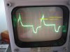
Here's the input waveform at point (A) in the circuit:
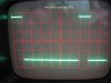
Here's the output waveform to the LM-2:
So I came up with a circuit that provides a clean square wave pulse to the LM-2. It’s worked flawlessly for a few years now. The circuit is nothing more than a ‘one-shot’ that triggers on the tach pulse from the coil front ended by a voltage comparator to get above the ringing in the tach waveform. The baluns (coil looking thingys in the schematic) are not required but I still have them installed.
There's probably other simpler ways to do this but it works for me. Also, here's a cool free circuit simulator I find handy. http://www.falstad.com/circuit/
Here's the circuit:
Here's the input waveform at point (A) in the circuit:
Here's the output waveform to the LM-2:
")