I wondered about that too and I agree with you. I think I'm ok with where the cam ended up at, I checked about a dozen times lol. I appreciate any input."Being a little retarded is fine as the chain tends to stretch some"
Must be a typo? Should it not be advanced
You are using an out of date browser. It may not display this or other websites correctly.
You should upgrade or use an alternative browser.
You should upgrade or use an alternative browser.
My Cam Research for the Experts Eye
- Thread starter TXChevy
- Start date
I'll go back to see if I recorded the centerline data, I may not have as I was focused on the open/close valve events.
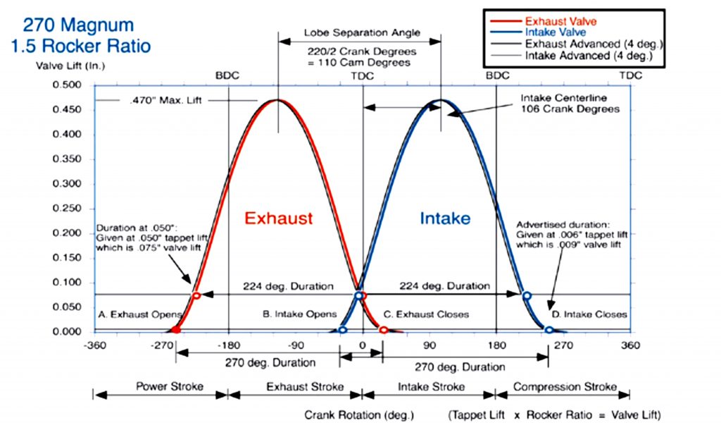
Looking/measuring cam lobe centerlines will not work on a asymmetrical cam lobe since the highest lift point is not necessarily in the middle. But I couldn't help but calculate the centerlines. In this case the centerline is half way thru the duration.based on your .050" measurements of the opening/closing events, except for what Straub speced for his camshaft.The lobes we use for these are not symmetrical, so a quick centerline method can give a false reading.
What diameter was the degree wheel that you used?
Centerline = [ (Open + Close +180) / 2 ] - Open


It does look like Straub ground his cam 4° advanced.
(113 - 105) / 2 = 4°
.
almost EVERY manufacturer grinds their cams 4 degrees advanced if installed with the dot-to-dot install method vs the split over lap method, or strait up install, advancing the cam 4 degrees closes the intake valve earlier and the compression begins earlier. Cams are usually designed to run with some advance and 4 would be typical. this is a practice many cam manufacturers decided helped marginally .because back in the past, many cam manufacturers found customers tended to select cam grinds that had a bit more duration or were marginally to wild for the application, under the idea, that many guys seemed to think of, (that was all too common, back in the 1950s-1980s and its still not uncommon)
(it the cam the tech guys suggested had (x) duration Ill just select the next bigger cam and get even more power)
(it the cam the tech guys suggested had (x) duration Ill just select the next bigger cam and get even more power)
degree it in correctly and get it to last,cam install info,
IM frequently asked (why bother degreeing in a cam, the timing set comes with index marks to install it?) it basically comes down to, a question of do you accept a random install where the timing can be almost any place randomly or do you insist on maximizing the engines potential and know...
garage.grumpysperformance.com
Cam degreeing
Degreeing – In the Camshaft New racing camshafts have a cam card included that shows the specifications for that camshaft. Degreeing In the cam means verifying that the valve timing and lift are close the specifications printed on the cam card. There are several reasons to degree in a...
garage.grumpysperformance.com
degreeing cam and shifting the lca
I finally got to degree my cam tonight. First cam I've ever done on a build. How far off the cam card timing numbers before most builders would correct with adv/ret? My cam timing numbers were withing 1 to 1.5 degrees and my intake and exhaust C.L. were withing 1/2 a degree...
garage.grumpysperformance.com
back in the 1950s to maybe the 1980s cam catalogs looked like this rather frequently and if the customer even bothered to talk with the tech department he may have gotten a valid suggestion, but his friend might have installed a cam #xyz and he found it ran really great in his car, so the all too common tendency, that the cam company's dealt with was that if joe average found that #xyz cam ran great, most of his buddys order the next larger cam, figuring it would run even better in their car! advancing the cam 4 degrees tended to allow a cam with too much duration for the application to run as bit better than it would have if installed at split overlap in an application it was really a bit too large for.
thus reducing the number of customer complains just a bit, back in the day I knew many guys who loved having a car with a lopey idle, as they cruised the local hamburger joint parking lot, it sounded COOL, but back then not 1 guy in 5 really understood how to match a cam to the engines drive train, compression or ignition timing, or tune a carb worth a damn
COMP CAMS EVEN SELLS THE
 www.onallcylinders.com
thus reducing the number of customer complains just a bit, back in the day I knew many guys who loved having a car with a lopey idle, as they cruised the local hamburger joint parking lot, it sounded COOL, but back then not 1 guy in 5 really understood how to match a cam to the engines drive train, compression or ignition timing, or tune a carb worth a damn
COMP CAMS EVEN SELLS THE
Thumpr™ line of cams that they freely admit make significantly LESS power than many of the other cam lines but they are designed PRIMARILY to produce a noticeably LOPEY IDLE
Do Cam Manufacturers Grind Advance Into Their Camshafts?
How and why cam manufacturers grind advance into their camshafts.
www.onallcylinders.com
The Mechanics of Adv/Ret a Camshaft ?
Without getting into the $150 and up range for timing gears and chain. There seems to be only two ways to adjust the timing for under $75, the crank gear can have several keyways or you can drill the cam gear and use bushings. Pulling the crank gear would be alot more of a pain to change, than...
garage.grumpysperformance.com
Last edited:
how your cam LSA effects your compression ,torque , DCR
TIGHTER 104-110 LSA tend to increase scavenging efficincy but at the cost of less smooth idle LSA lobe separation angle is locked into the cam when its ground and can not change, if its ground at 110,degrees or 114 degrees it will stay that figure and LCA lobe center angle, can be...
garage.grumpysperformance.com
semi fool proof cam sellection
you can start with this, the SIX cam manufacturers POSTED OR LINKED BELOW that have proven to be dependable, the soft ware below might prove useful, so use it to get a base line INFO YOU NEED IF YOUR selecting the correct cam for YOUR combo FIRST!!>>>>>>ANY AND ALL CAM MANUFACTURERS WILL need...
garage.grumpysperformance.com
sellecting valve springs, and setting up the valve train
How do you determine the spring pressure needed to keep the valves under control for a given lift, duration, and max rpm. It might take you several hours to read thru all the links and sub links but its time very well spent as it could save your engine from destruction and save you thousands of...
garage.grumpysperformance.com
do you match the cam to the engine or build the engine to match the cam specs?
"do you match the cam to the engine or build the engine to match the cam specs?" I got asked that question a few days ago, frankly I have never ever considered doing it either way heres some basics that won,t change theres a couple thousand related threads here to help you. You may find this a...
garage.grumpysperformance.com
JROD said:Most cams from the aftermarket come with +4 ground in from the very start. So, on a 114LSA you end up with a 110ICL. Add another +4 and you are at a 106ICL. LSA cannot change ICL can as a function of an adjustable timing gear. Read the Comp article on cam basics.
Also, some of this might be a bit to much on the techo-babble side. But here goes...
Lobe centerline: This represents an imaginary line referenced from the true center of the base circle out to the end of each lobe, in crankshaft rotational degrees. Intake centerline values are found in the crankshafts rotation ATDC, while exhaust centerlines are found at travel BTDC. Lobe centerlines are commonly thought to be the actual mid-point of the flank and are usually close to that, but different ramps on the opening and closing sides may change that reading. For this reason the true center of the cam core is used as a reference. For those who use the intake centerline method for degreeing in a camshaft, you can now see how if the phase of the camshaft is off, it will require a different amount of crankshaft rotation to find this point. When using the intake centerline method lower crankshaft rotational degrees represent the cam being in early or advanced. This statement is correct since in relation to the crankshaft's rotation ATDC, the valve event happens sooner.
Lobe separation angle (LSA): LSA is measured in camshaft degrees and refers to the amount of rotation it takes to travel from the intake centerline to the exhaust centerline. As this number grows, the distance between the centerlines is spread out. Often LSA is considered an indicator of overlap, or the period of time that both valves are open on the same cylinder. Because it is a partial function of LSA, overlap can be calculated with fair accuracy using duration and LSA values. The issue concerning this is you need accurate duration numbers at 0.006 inch to calculate overlap at the industry standard.
The following equation can be used for the approximation of overlap:
For single pattern (duration being equal on both the intake and exhaust lobes):
Overlap = Dur. - 2 X (LSA)
For split-duration cams (different durations on intake and exhaust lobes):
Overlap = Intake Dur. + Exhaust Dur./2 - 2 X (LSA)
NOTE: Non-symmetrical cam lobes will have increased error using these calculations.
Not a single function of LSA alone, overlap is affected by changes in centerlines, ramp designs, and duration. The rumpty-rump sound that we all love in a hot LSx engine is the hallmark of overlap. Used to help scavenge the cylinder, overlap is a function of the complete cam design.
Now some VERY general info on what advancing a cam will do.
By advancing the cam, the valves open and close earlier. Duration and overlap remain unchanged. Advancing raises the cylinder pressure (due to earlier valve closing) This improves low end and mid-range torque at the expense of some top-end power. The result is similar to using a shorter-duration cam since the intake valve closing point is more critical than its opening point.
Retarding the cam so valves open and close later has the opposite effect. This should increase top-end power, at the expense of low end, and mid-range torque. Thus: 1) Advance Cam: More low and mid-range torque, 2) Retard Cam: More top-end power.
Advancing and retarding are easily accomplished with offset bushings or keys for the cam or crankshaft, depending on the engine. The bushings and keys are usually supplied in increments of 2, 4, 6, and 8 crankshaft degrees. Remember that one crankshaft degree equals two camshaft degrees.
Trial and error is usually the best method when advancing or retarding a cam to alter performance. I.E. make a change go make passes and see if the car makes more power.
Before attempting to advance or retard a cam, you must know the actual valve timing, not the manufacturer's specifications. I.E. Use a degree wheel and don't believe your cam card. They have been known to be wrong...
Advancing and retarding a camshaft will move valves closer to the piston. Valve-to-piston clearance must be checked after advancing or retarding alterations to prevent possible engine damage. Also, changing the cam timing will also change ignition timing, which must then be reset.
A bit of the same info from Crane...
What is meant by basic RPM?
The camshaft’s basic RPM is the RPM range within which the engine will produce its best power. The width of this power band is approximately 3000 to 3500 RPM with standard lifter cams, and 3500 to 4000 RPM with roller lifter cams. It is important that you select the camshaft with the “Basic RPM Range” best suited to your application, vehicle gearing and tire diameter.
What is camshaft duration and why is it important?
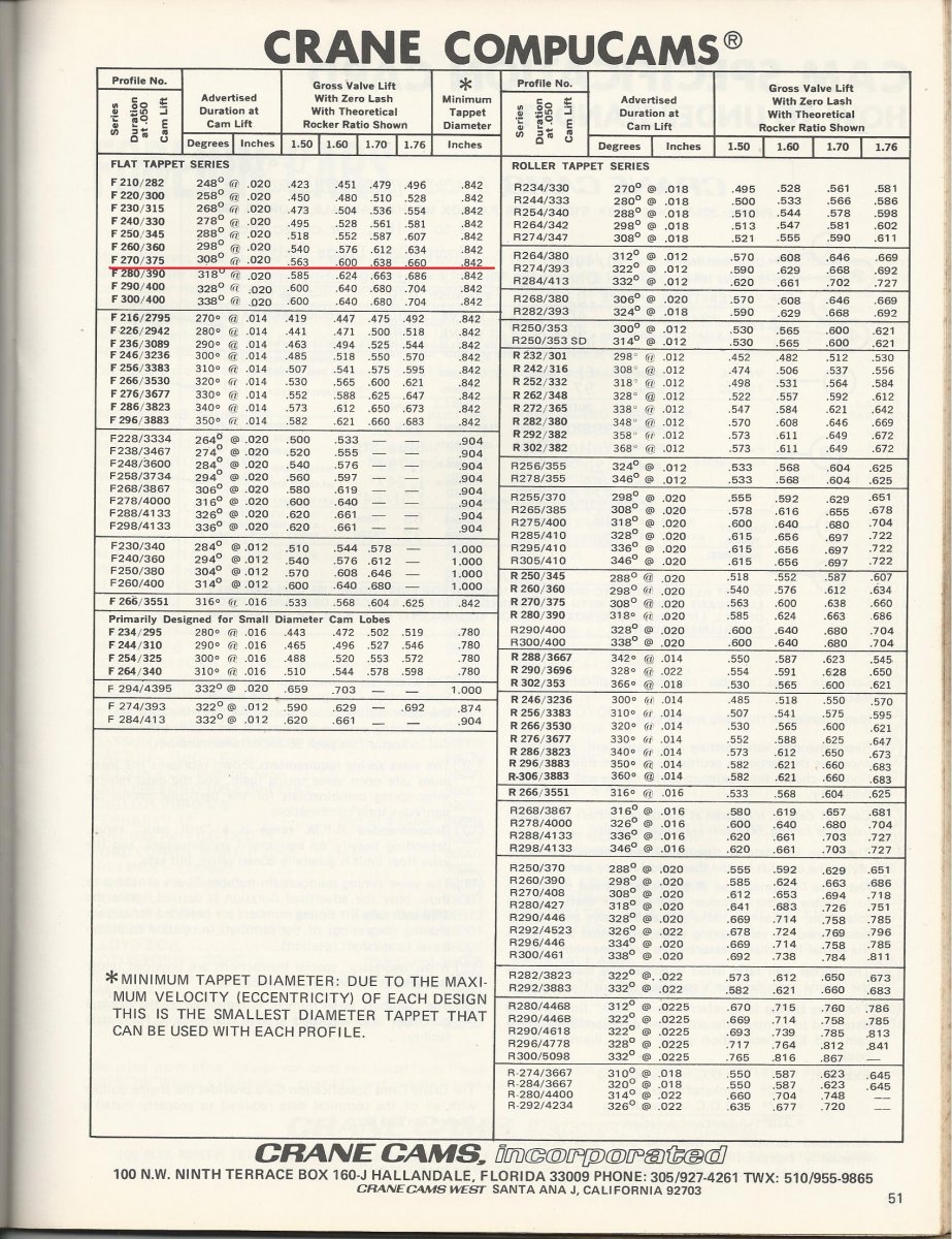
Duration is the period of time, measured in degrees of crankshaft rotation, that a valve is open. Duration (at .050” lifter rise) is the deciding factor to what the engine’s basic RPM range will be. Lower duration cams produce the power in the lower RPM range. Larger duration cams operate at higher RPM, but you will lose bottom end power to gain top end power as the duration is increased. (For each ten degree change in the duration at .050”, the power band moves up or down in RPM range by approximately 500 RPM’s.)
What is the difference in advertised duration and duration at .050” lifter rise (Tappet Lift)?
In order for duration to have any merit as a measurement for comparing camshaft size, the method for determining the duration must be the same. There are two key components for measuring duration— the degrees of crankshaft rotation and at what point of lifter rise the measurements were taken. Advertised durations are not taken at any consistent point of lifter rise, so these numbers can vary greatly. For this reason, advertised duration figures are not good for comparing cams. Duration values expressed at .050” lifter rise state the exact point the measurement was taken. These are the only duration figures that are consistent and can accurately be used to compare camshafts.
How does valve lift affect the operation of an engine?
Lift is the distance the valve actually travels. It is created by the cam lobe lift, which is then increased by the rocker arm ratio. The amount of lift you have and the speed at which the valve moves is a key factor in determining the torque the engine will produce.
What is camshaft lobe separation and how does it affect the engine?
Lobe separation is the distance (in camshaft degrees) that the intake and exhaust lobe centerlines (for a given cylinder) are spread apart. Lobe separation is a physical characteristic of the camshaft and cannot be changed without regrinding the lobes. This separation determines where peak torque will occur within the engine’s power range. Tight lobe separations (such as 106°) cause the peak torque to build early in basic RPM range of the cam. The torque will be concentrated, build quickly and peak out. Broader lobe separations (such as 112°) allows the torque to be spread over a broader portion of the basic RPM range and shows better power through the upper RPM.
What are intake and exhaust centerlines?
The centerline of either the intake or exhaust lobe is the theoretical maximum lift point of the lobe in relationship to Top Dead Center in degrees of crankshaft rotation. (They are shown at the bottom of the camshaft specification card as “MAX LIFT.”) The centerlines of the intake and exhaust lobes can be moved by installing the camshaft in the engine to an advanced or a retarded position. Generally speaking, the average of the intake and exhaust lobe centerline figures is the camshaft lobe separation in camshaft degrees.
How does advancing or retarding the camshaft’s position in the engine affect performance?
Advancing the cam will shift the basic RPM range downward. Four degrees of advance (from the original position) will cause the power range to start approximately 200 RPM sooner. Retarding it this same amount will move the power upward approximately 200 RPM. This can be helpful for tuning the power range to match your situation. If the correct cam has been selected for a particular application, installing it in the normal “straight up” position (per the opening and closing events at .050” lifter rise on the spec card) is the best starting point.
Why is it necessary to know the compression ratio of an engine in order to choose the correct cam?
The compression ratio of the engine is one of three key factors in determining the engine’s cylinder pressure. The other two are the duration of the camshaft (at .050” lifter rise) and the position of the cam in the engine (advanced or retarded). The result of how these three factors interact with one another is the amount of cylinder pressure the engine will generate. (This is usually expressed as the “cranking pressure” that can be measured with a gauge installed in the spark plug hole.)
It is important to be sure that the engine’s compression ratio matches the recommended ratio for the cam you are selecting. Too little compression ratio (or too much duration) will cause the cylinder pressure to drop. This will lower the power output of the engine. With too much compression ratio (or too little duration) the cylinder pressure will be too high, causing pre-ignition and detonation. This condition could severely damage engine components. It is important to follow the guidelines for compression shown on the application pages of the catalog.
How does cylinder pressure relate to the octane rating of today’s unleaded fuel?
In very basic terms, the more cylinder pressure we make the more power the engine will produce. But look out for the fuel! Today’s pump gas is too volatile and cannot tolerate high compression ratio (above 10.5:1) and high cylinder pressure (above approximately 165 PSI) without risking detonation. Fuel octane boosters or expensive racing gasoline will be necessary if too much cylinder pressure is generated.
How does an increase in rocker arm ratio improve the engine’s performance?
The lobe lift of the cam is increased by the ratio of the rocker arm to produce the final amount of valve lift. A cam with a .320” lobe lift using a 1.50:1 ratio rocker arm will have a .480” valve lift (.320” x 1.50 = .480”). If you install rocker arms with an increased ratio of 1.60:1, with the same cam, the lift would increase to .512” (.320” x 1.60 = .512”). The engine reacts to the movement of the valve. It doesn’t know how the increased lift was generated. It responds the same way it would as if a slightly larger lift cam had been installed. In fact, since the speed of the valve is increased with the higher rocker arm ratio, the engine thinks it has also gained 2° to 4° of camshaft duration.
Thanks again for the knowledge base info!
Rick, I used a 10" diameter degree wheel with a pointer I made. I had put a very fine point on the pointer to be as accurate as possible against the wheel.
Your chart is super helpful for me to see the correlation of the different settings, and especially showing the basic formula for calculating centerline.
I agree from the info that's provided, that it seems that the cam was ground with the +4 degrees as the dot to dot position. I now also better understand your comment about the +4 degree setting actually indicating valve timing readings more of +8 degrees.
So if I'm understanding right, by my -2 degree install, it may still be a couple degrees advanced? At any rate, it seems that it should be ok at this setting and from the info Grumpy posted, this may (even slightly) reduce the tendency towards detonation. As far as any impact to hp/tq, that's not really an issue for me.
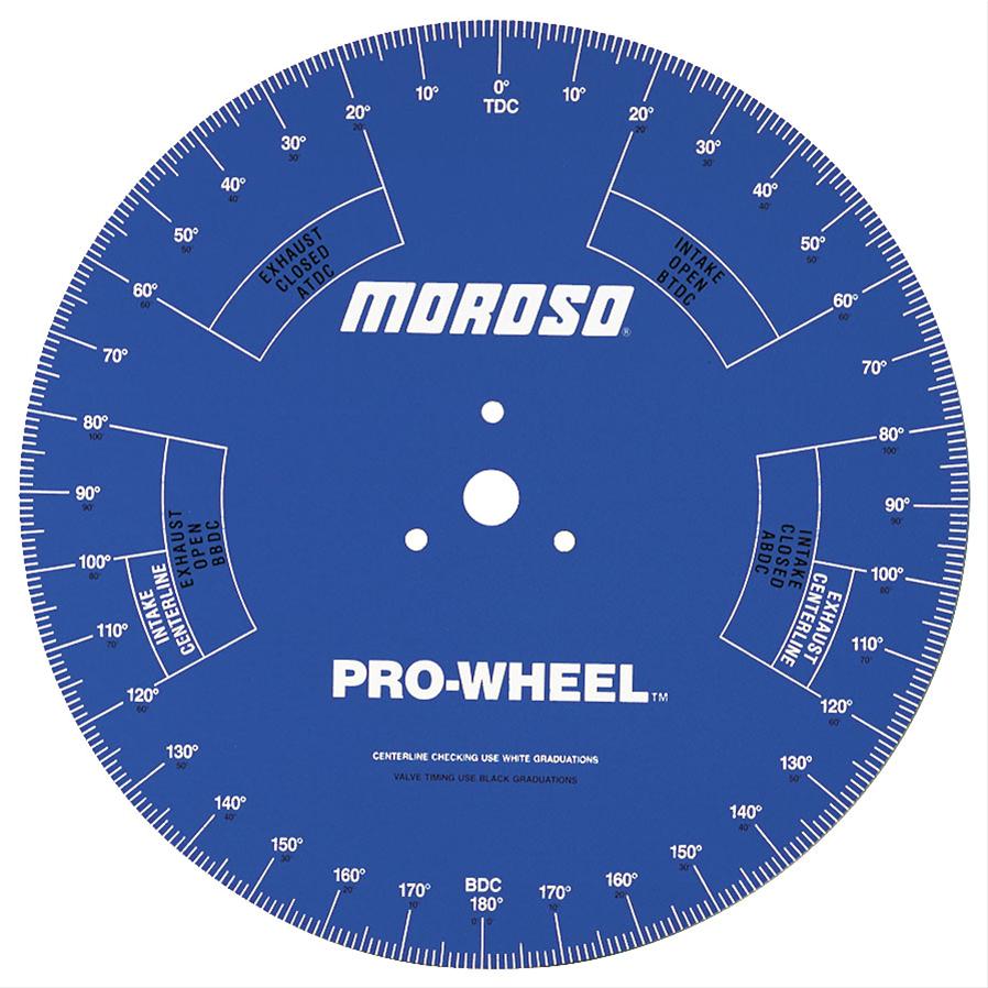
To be honest, I would not have been happy with more than a 1° of error. The 10" wheel would contribute to your error. I would suggest the Moroso degree wheel next time it is both bigger and comes at a reasonable price. Although it seems to be much higher now then when I bought it back in 2015. The spaces for each single degree on this 18" wheel is going be significantly larger than on a 10" wheel.Rick, I used a 10" diameter degree wheel with a pointer I made.
The arc length of 1° on a 10" wheel = .087"
The arc length of 1° on a 18" wheel = .157"
Moroso 62191 Moroso Pro Degree Wheels | Summit Racing
Free Shipping - Moroso Pro Degree Wheels with qualifying orders of $109. Shop Degree Wheels at Summit Racing.

If we are talking in absolute numbers and NOT relative numbers, then yes you are correct. You installed the cam "2° Advanced".So if I'm understanding right, by my -2 degree install, it may still be a couple degrees advanced?
When the overlap is split equally, then there is NO Advance or Retard of the cam timing. You can ignore what the cam manufacture did.
This is all a little bit muddy when you have an asymmetrical cam lobe like you do, cause now it depends on how you define the center of the lobe. Highest lift or middle of the duration.
It will be 100% OK !!! Yes it will reduce your DCR and therefore will be slightly better for detonation. I don't think you will be able to tell the difference, only could tell by measuring the difference.At any rate, it seems that it should be ok at this setting and from the info Grumpy posted, this may (even slightly) reduce the tendency towards detonation. As far as any impact to hp/tq, that's not really an issue for me.
Last edited:
Hey Thunderbolt, didn't want to let your comment go unanswered."Being a little retarded is fine as the chain tends to stretch some"
Must be a typo? Should it not be advanced?
It seems to me that as the chain stretches, then the cam is going to lag behind the crankshaft more then when it was tight The valve springs are going to provide a drag on the cam, therefore trying to slow it down and take up the chain slack such that it retards the cam.
What do you think?
I agree about the larger degree wheel yielding less chance of discrepancy. I had noted the possible1-2d discrepancy in that little chart I made, I wanted to remember later.
Maybe no real impact but I had used a longer pointer that was easier to align with the wheel center. My hope was that if the pointer was straight to center axis it would help accuracy.

You're right, the -2 degree settung is actually advancing valve events.
Easy now to second guess myself lol. Always good to verify things though!
Maybe no real impact but I had used a longer pointer that was easier to align with the wheel center. My hope was that if the pointer was straight to center axis it would help accuracy.
You're right, the -2 degree settung is actually advancing valve events.
Easy now to second guess myself lol. Always good to verify things though!
")
Thunderbolt
Well-Known Member
First a disclaimer, i dont speak english, so i hope i get it right, Yes i think if the chain stretches the cam will be retarded relative to the crank, and installing the cam a little advanced should generaly be better than retarded.Hey Thunderbolt, didn't want to let your comment go unanswered.
It seems to me that as the chain stretches, then the cam is going to lag behind the crankshaft more then when it was tight The valve springs are going to provide a drag on the cam, therefore trying to slow it down and take up the chain slack such that it retards the cam.
What do you think?
While I'm getting the radiator and cooling done I'll also start checking electrical circuits.
This worked out pretty good -
I wanted a large AGM battery. My car takes H8 AGM, it was 4 yrs old but working fine. So I got new H8, put it into my car and put old battery into 57.

The battery box end panel is removed in the pic. It's a breeze to install the battery, just unbolt the end panel and pull out the battery. It fits perfect inside the box front to back and I'll use wood blocking as needed on the sides. I've also made a crossbar tiedown to keep the battery secured. AGM vent is just a 1/4" tube at one end of the battery very easy to route outside.
This worked out pretty good -
I wanted a large AGM battery. My car takes H8 AGM, it was 4 yrs old but working fine. So I got new H8, put it into my car and put old battery into 57.
The battery box end panel is removed in the pic. It's a breeze to install the battery, just unbolt the end panel and pull out the battery. It fits perfect inside the box front to back and I'll use wood blocking as needed on the sides. I've also made a crossbar tiedown to keep the battery secured. AGM vent is just a 1/4" tube at one end of the battery very easy to route outside.

Radiator was in good shape, but I cleaned and polished it up. Getting the hoses squared away - I've not found any that fit without modification, but not a big deal.

A little accident avoidance till I'm ready to start the engine.

Im not installing the electric fans right now - I'll use one of those bounce house blowers in front of the radiator. They put out a lot of air, enough to get initial running done.
The rivetnuts I've added made attaching the radiator, side panels, etc a breeze. No more fishing around the back trying to get a nut on a bolt.

A little accident avoidance till I'm ready to start the engine.
Im not installing the electric fans right now - I'll use one of those bounce house blowers in front of the radiator. They put out a lot of air, enough to get initial running done.
The rivetnuts I've added made attaching the radiator, side panels, etc a breeze. No more fishing around the back trying to get a nut on a bolt.
Small details always take time... I checked plug wire resistance and they're all good. Except that I want 135 degree boots instead of the straight boots.
Rather than buy a complete set, I'll just get the different boots. I've got the crimper needed for the ends.

Rather than buy a complete set, I'll just get the different boots. I've got the crimper needed for the ends.
Now that you got it looking great, you should spray it with some Cerakote MC-5100. It's tack free in 15-30 minutes, does not require thinning and it flows out very nicely. Good up to 300°F. Once it's fully cured in 24 hours nothing will touch it, not brake fluid, brake kleen, acetone, alcohol, etc.Radiator was in good shape, but I cleaned and polished it up.
It been on my trailer fenders for over a year and still looks like the picture.
Cerakote - CERAKOTE CLEAR - ALUMINUM
Shop Cerakote CERAKOTE CLEAR - ALUMINUM MC-5100. Find the coating that fits your application. Choose from a wide variety of coatings with specific attributes and specialties.

.