rear mains DO generally have slightly larger clearances ON purpose, you look fine.
http://kingbearings.com/files/Engine_Be ... erials.pdf
Influence of Grooved Main Bearings on Performance
http://www.enginebuildermag.com/Article ... mance.aspx
http://www.stealth316.com/misc/clevite- ... ooving.pdf
Manufacturers are frequently asked what difference grooving makes. Various forms of main bearing grooving have been used over the years.
https://www.carshopinc.com/product_info.php/products_id/49347/SPG1-12
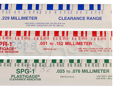
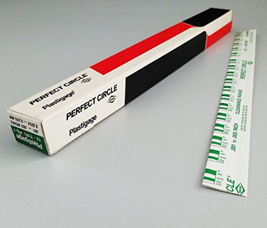
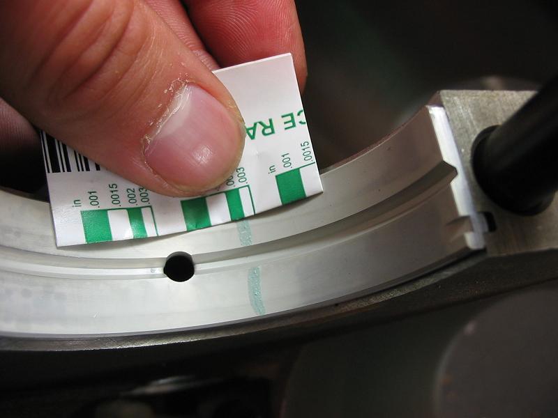
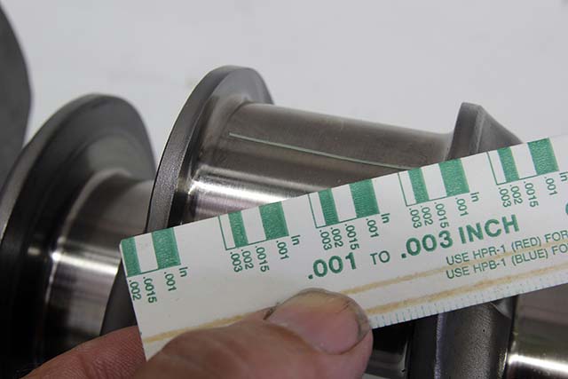
yes I use both micrometers and snap gauges and cross check with plasti-gauge
and yes when you compare the crushed width of the plasti-gauge youll find it rarely falls as an exact match to the bar chart tape that is packaged with it so you can judge clearance based on crush width
http://garage.grumpysperformance.com/index.php?threads/bearing-clearances.2726/
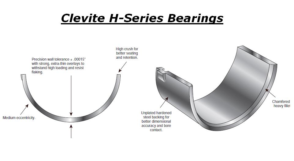
It’s essential to understand that bearings depend on a film of oil to keep them separated from the shaft surface. This oil film is developed by shaft rotation. As the shaft rotates it pulls oil into the loaded area of the bearing and rides up on this film much like a tire hydroplaning on wet pavement.
Grooving in a bearing acts like tread in a tire to break up the oil film. While you want your tires to grip the road, you don’t want your bearings to grip the shaft, so grooving is bad for maintaining an oil film. The primary reason for having any grooving in a main bearing is to provide oil to the connecting rods. Without rod bearings to feed, a simple oil hole would be sufficient to lubricate a main bearing.
Many early engines used full grooved bearings and some even used multiple grooves. Those choices were based on what engineers knew at the time.
As engine and bearing technology developed, the negative effect of grooving was recognized and bearing grooving was removed from modern lower main bearings. The result is in a thicker film of oil for the shaft to ride on.
This provides a greater safety margin and improved bearing life. Upper main shells, which see lower loads than the lowers, and hence don’t apply the same load to the oil film, have retained a groove to supply the connecting rods with oil.
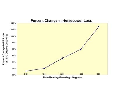
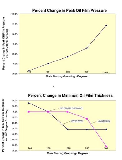
In an effort to develop the best possible main bearing designs for high performance engines, manufacturers have investigated the effects of main bearing grooving on bearing performance. The graphs (Figure 1) illustrate that a simple 180° groove in the upper main shell is still the best overall design.
While a slightly shorter groove of 140° provides a marginal gain, most of the benefit is to the upper shell, which doesn’t need improvement. On the other hand, extending the groove into the lower half, even as little as 20° at each parting line (220° in total), takes away from upper bearing performance without providing any benefit to the lower half. It’s also interesting to note that as groove length increases so does horsepower loss and peak oil film pressure, which is transmitted directly to the bearing.
Notes: You will still find some full-grooved main sets offered for older engines where demand is low and the engineering cost to bring the sets to current standards is not warranted (bearings generally represent the technology of the time the engine was developed).