Port Matching Intake Manifold to Heads

Indycars

Administrator
Staff member

I've spent several hours thinking about how to align the Intake Manifold, Gasket and Brodix Heads. It's not as easy as it sounds, the bolt holes in the gasket (FelPro 1206) are larger than the bolts. Leaving the gasket to shift maybe 1/16", so there is no telling where it will be during final assembly.

The best idea I've found on the internet is assembling the top end with gaskets and then drilling a 1/8" hole thru the intake, gasket and into the head about 1/8", then using a drill bit or dowel pin as an index for looking both directions while matching the Intake Manifold ports / Head ports to the gasket. I would be a little nervous doing this, maybe it's a machine shop procedure.

Does anyone have a procedure that can be performed by an individual in his own garage ???
 
first thought,
don,t be really overly concerned with what is effectively at most a minor factor in the engines performance, because ports are rarely opened up to the max intake gasket diameter and a minor miss alignment on the gasket of 1/32" or so has very little effect on flow rates.


but yes there is a few ways to center the hole in the gasket around the bolts holding the intake in place, you can buy one of these o-ring kits for $8, and slide the appropriate diam o-ring over the bolt, after inserting in the intake manifold bolt, the o-ring will center the bolt in the intake gasket as you tighten/clamp the intake as it is forced into the slightly larger hole in the gasket. this is not always 100% precise but its amazingly consistent provided you always use the exact same intake gasket part number on the cars engine
(provided of course that the intake gasket manufacturer keeps the intake gaskets consistent)
portmatching.jpg


vgd5.jpg

image_4829.jpg

portw1.jpg

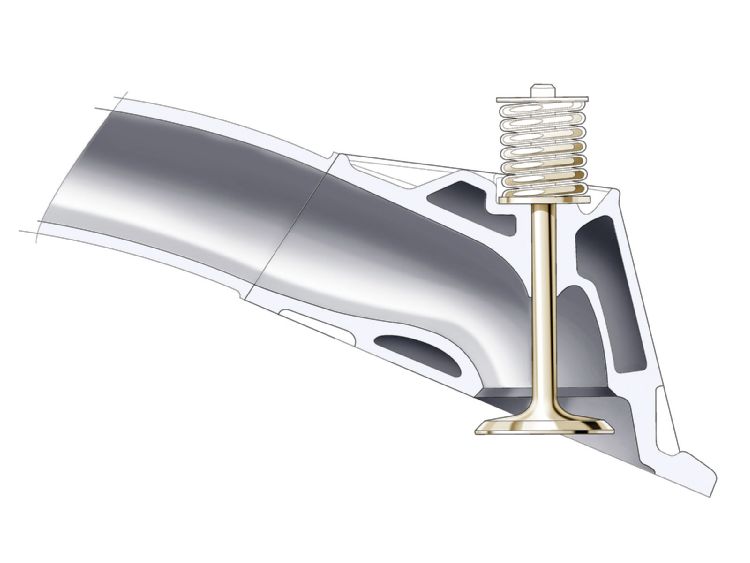
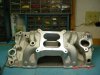
most intakes require gasket matching to maximize the flow potential
portw2.jpg

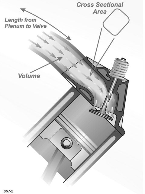
simply open the ports to match and transition too the heads and blend back any change in cross sectional area up the runners at least an inch or more
portw3.jpg

don,t forget the plenum and runner entrance needs smoothing


https://www.summitracing.com/parts/...Hci_rngCjPIi0Hzl27DmoGKgPl5jkEzRoCXYoQAvD_BwE

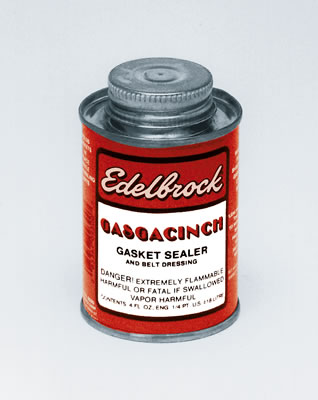
use of a gasket sealer that helps prevent gasket movement helps
edl-9300.jpg

OR YOU CAN
AND, its far more precise if buy a box of roll pins and carefully drill thru both the intake and head, a twin set of two 3/32" holes about a 1/3" deep, parallel to and just above the two outer intake bolt,s and place the roll pin in that hole drilled in the heads just above the two outer intake bolts about 1/4" higher on the heads , insert a roll pin so it sticks up ONLY about a 1/8", so it BARELY protrudes above the gasket surface so you can index the intake GASKET on the pins preventing it from shifting location after punching matched location holes in the gaskets, with the punch listed below
then go back and trial fit/ install the intake manifold after painting the tips of the roll pins with machinist bluing dye to precisely locate the place to drill the intake flange on the intake manifold and re-drill just the intake manifold flange hole that aligns with the roll pin to 1/8" diam. so its got a bit of movement as its dropped into place over the tip of the roll pins, some guys drill the center of the front and rear block china wall and insert a roll pin and drill an alignment hole in the intake as well, there as doing so insures duplication of the intakes exact consistent repeat alignment as it lowered vertically onto the heads. once you've got the intake gasket located in a 100% repeatable location on the heads you can use the same alignment holes to hold the gasket on the intake manifold flange with tiny bolts and nut so you can spray the intake ports in the intake manifold with machinist blue to locate the exact area that needs to be matched.
yes if you want every thing 100% perfect it can be done, but, Id suggest you don,t be really overly concerned with what is effectively at most a minor factor in the engines performance, because ports are rarely opened up to the max intake gasket diameter and a minor miss alignment on the gasket of 1/32" or so has very little effect on flow rates.

image_6183.jpg

http://www.harborfreight.com/315-piece- ... 67682.html
http://performanceolds307.tripod.com/id29.html

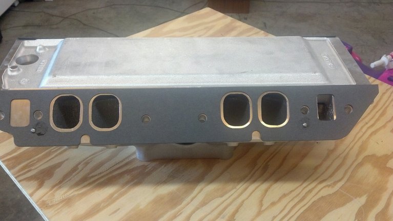
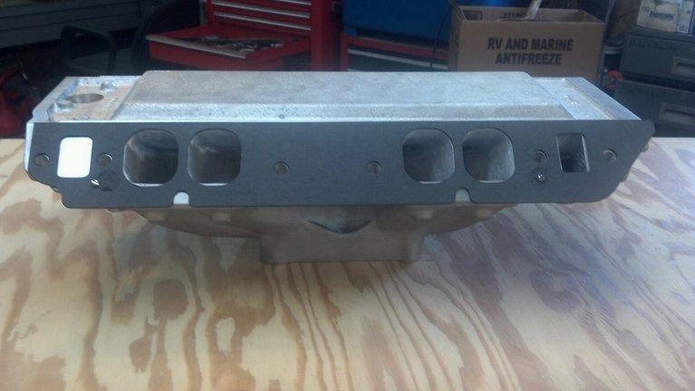
How to PORT MATCH a intake manifold to the heads. Port matching is a good idea, it assures the intake manifolds port runners match up perfectly to the intake ports on the heads. Heres the how too.

First use felpro intake gaskets for this job because they are the only ones I found to perfectly match up with the heads, but intake manifolds never match up so thats why we gotta port match them.

1. Take a old intake gasket turkey tray and install the intake (thats gonna be port matched) on the engine. Torque down to specs.
2. Remove the 4 intake bolts on the 4 edges of the intake.
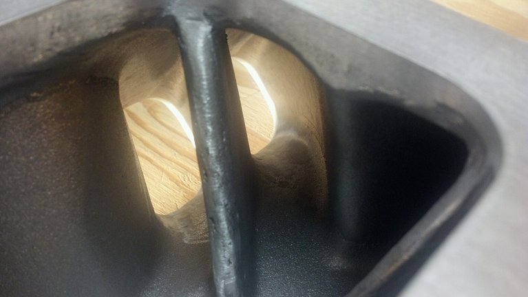
3. Use a small drill bit and drill 4 small holes in the intake just over the holes of the 4 bolts you just removed (One per bolt hole of course). Drill through the intake and intake gasket, untill it just barely starts to go into the head. No need in going in the head, just go enough to make a mark on it. (Check pictures below)
4. After doing that to all 4 corners, remove the intake and gasket.
5. With the intake and gasket off the car. Now you can hold the gasket up to the intake and match the 4 holes you drilled though the intake and gasket.
6. With the intake gasket held on the intake and the 4 holes matched up, take a razor and scrub on the intakes flange around the outer edge of the intake gaskets ports (tracing the size, location and shape of the intake gaskets port onto the intake manifold). This will be used as a guide when your porting out the intake. Make sure to do that to all 8 intake ports
7. Now remove the gasket and start port matching. Start on the outer edge of the intakes port, bring the port size to about 0.5mm away from the mark you scrubed on it with the razor (becuase its always better to undercut then overcut).
8. After getting the ports opening to the size and shape of the scrubed mark then proceed to slow taper the opening of the ports inward into the intake. You should only take it in about 3 inches if your just port matching the intake. By 3 inches it should be tapered to match the original surface in such a smooth manner that you cant tell were you tapered it at. If its a full port job then use this size and shape as a guide all the way in if possible.
9. When your all done, take the new intake gasket and drill 4 holes in it in the same exact location as the old intake gasket used for the porting. Just hold the two gaskets over eachother to get the perfect location to drill.
10. After drilling the 4 holes place the new gasket on the engine and press in the gaskets locating pins so the gasket is perfectly in place.
11. Varify the 4 holes drilled in the intake gasket matches the 4 holes drilled in the heads. It does! Good!
12. Install the intake and new intake gasket with normal torque technics but keep a close eye on all the 4 holes, making sure the intake is falling back into its original position along with the intake gasket.
13. When your all done you should be able to look into every hole you drilled and see through the intake, intake gasket and right onto the head. At this point you can be sure that it is all "port matched"

http://www.harborfreight.com/382-piece- ... 67554.html

viewtopic.php?f=55&t=5378&p=16106&hilit=port+match#p16106

viewtopic.php?f=52&t=2971&p=7799&hilit=gasket+match#p7799

viewtopic.php?f=55&t=2773&p=7200&hilit=+port+match#p7200

IF YOU GO THE ROLL PIN ROUTE BUY ONE OF THESE IT MAKES PUNCHING THE INTAKE GASKET HOLES FAR EASIER
image_3944.jpg

http://www.harborfreight.com/leather-pu ... 97715.html


swirlpic.jpg


porting+valve_area.jpg


air_flow_pattern.jpg


0412em_18_z+cylinder_head_porting+.jpg


shroudhead_porting+.jpg


PORM1.jpg


PORM2.jpg

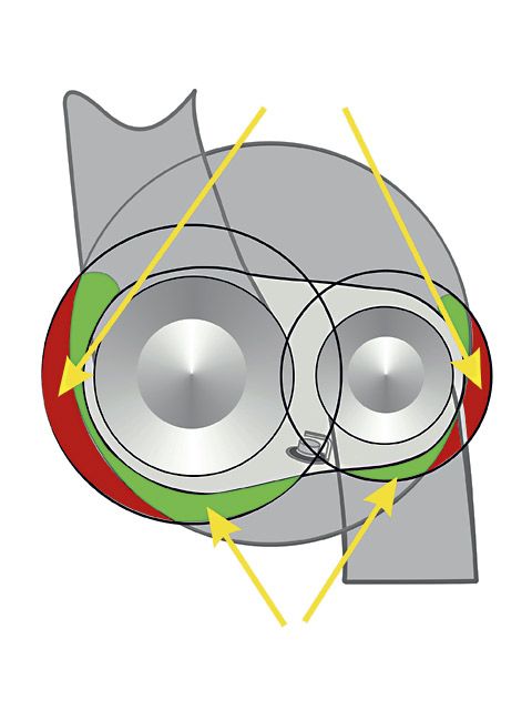
typical vortec head ports before being matched to gaskets

PORM3.jpg

aluminum small vortec style aftermarket port heads before port match

PORM4.jpg

aluminum small vortec style aftermarket port heads after port match
its not at all unusually to gain significant flow increases if the ports and intake are matched, but its not always a huge increase in every case, a good deal depends on the components used and the cam selected, theres not much gained if the potential port flow has increased lets say 40% at .700 lift if the cam and intake being used reduce flow and valve lift to well below those potential flow rates.
Ive ported killer sbc heads ,and then tested them before and after on a freinds flow bench, heads that flowed 280cfm out of the box too flow 316 cfm at .700 lift after port clean up work,and once you install an intake on hose same heads, and set the valves at .500 lift like the cam being used in the build you find you have 257 cfm of flow


USE THE CALCULATORS to match port size to intended rpm levels... but keep in mind valve lift and port flow limitations[/color]

http://www.wallaceracing.com/runnertorquecalc.php
http://www.wallaceracing.com/ca-calc.php
http://www.wallaceracing.com/area-under-curve.php
http://www.wallaceracing.com/chokepoint.php
http://www.wallaceracing.com/header_length.php
 
Last edited by a moderator:

Thanks, that's what I was looking for. Looks like I could do this myself without the help of a machine shop.
 
OR YOU CAN
AND, its far more precise if buy a box of roll pins and carefully drill thru both the intake and head, a twin set of two 3/32" holes about a 1/3" deep, parallel to and just above the two outer intake bolt......
In the post above that start out like the quote, I had a hard time making clear sense of it all. So I tried to re-write it with some pictures like I thought you meant it to say. Please let me know where I've misunderstood.

---------------------------------------------------------------------------------------------------------------

Drill a set of 3/32 inch holes (one each end) into the head about a 1/3 inch deep, parallel to and just above the two outer intake bolts. See picture above.

Place a roll pin in that holes drilled in the head so they stick up ONLY about a 1/8". It should barely protrude above the gasket surface, so you can index the intake gasket on the pins. Align the intake gasket to the head, then mark and make matching holes with a leather punch.


Set the intake manifold into position with gasket and roll pins (2 pins total) in place. Start all 12 bolts first, then finger tighten. Once you're satisfied with the manifolds position, then lightly tighten the 6 bolts on the side with the 2 roll pins. This should leave a mark on the manifold where the holes need to be drilled. You may want to lightly tap the manifold with a hammer right above where the roll pins are located to make sure you have a noticeable mark. Drill these holes 1/8 inch diameter, making sure they are reasonably parallel to the holes in the head. Since the roll pins are 3/32 inch, this gives a needed 1/32 inch clearance, making final assembly easier.

Now disassemble and use the rolls pins to locate the gasket on the head and manifold for grinding to match.


some guys drill the center of the front and rear block china wall and insert a roll pin and drill an alignment hole in the intake as well, there as doing so insures duplication of the intakes exact consistent repeat alignment as it lowered vertically onto the heads.
Ok I've tried to figure out what china might be, but it's not coming to me. Are you referring to drilling and installing roll pins in the valley rails ??? Therefore helping to align the manifold as it's dropped into place.


Sorry for being so picky, but I need to fully understand before I start such a procedure.

.
.
.
 

Attachments

  • Head-IntakeSide01.jpg
    Head-IntakeSide01.jpg
    9.7 KB · Views: 444
  • IntakeManifold01.jpg
    IntakeManifold01.jpg
    24.5 KB · Views: 444
8_009.jpg


china wall= end rails walls


Intake Manifolds

Intake manifolds were one of the original hot rod parts, and they are still one of the first parts changed when more power is needed. Not only that, they are racy looking and save weight.


Technically, they are extensions of the intake ports in the heads. But unlike cylinder heads, porting and flowing of intakes has never received the popularity or interest of heads, and that has been a mistake. There may be thousands of shops in the United States that port cylinder heads. Many of them even have flow benches to test their work. Porting cylinder heads is a very mysterious subject filled with lots of theory, trial & error, lies and myths. But, at best, manifold exteriors are only painted or polished like some tuner bling. Some may be really tricked out with a "gasket match" woooo!!


A couple of years ago, we noticed that some of the higher flowing aluminum heads were not picking up power like they should have been based on the air flow improvements they provided (promised). Some investigation indicated that the manifolds many racers were using were not flowing as much air as the heads; in other words, the manifold had now become the bottle neck in the system.


In the Fall of 05, we started a program of flow testing intake manifolds. What we found, for one thing, is that the fixturing required is much more extensive than what is required to test cylinder heads. This is one of the reasons shops dont make a concentrated effort to test them. Some attempts to flow them in reverse (air flow backwards) have been done because the specialized fixturing is not required, but these tests dont give a true picture of the flow patterns. We have taken the time to create the unique fixturing allowing us to mount and flow test the intakes correctly. We are testing many manifolds some oldies of historical significance and the newest and latest pieces available.


This testing has not only confirmed that our suspicions were correct about manifolds air flow, but, what we have learned about unequal air flow from one port to another is shocking.Port to port flow varied as much as 60cfm! Unbelievable! Yes, 60cfm (at 28 DP) from the best to the worst port.

Some of the old favorites were actually fairly close on equal flow, within 20cfm, - no that is not as good as we would expect from heads, but this is what you have been getting. We were able to improve and equalize some intakes, others were very disappointing. One of the most interesting aspects was that those with the most equal port-to-port spread were the lowest flowing pieces and they are among some of the more popular intakes used in dyno shoot-out comparisons. This might indicate that equal, but lower flow is better than more flow, with some ports, giving a higher average flow. This is a poor trade-off at best, but interesting none-the-less.


One of the worst spread of port-to-port differences was 60cfm in a single plane manifold. This is unusual since single planes tend to be easier to make equal flowing.


We have modified some dual plane plenums with good results, mostly the newer pieces. Old dual planes that were modified made poor ports better. However, you would be better off with the newer manifolds. Port matching also provided some interesting results. The so-called gasket match about a 1/2" deep or less that is popular with some magazines and sanctioning bodies proved to be a waste of time or worse. However, a very deep port blend reaching as far as the eye could see, when applied properly, could be worth over 40cfm on some manifolds very significant! Blending is tricky. Some runners responded to inner wall work and some to outer wall, and we now know which works and which do not.


We have come to the conclusion that the 2x4 tunnel ram intakes ran so well, not because of the extra carb as much as the fact that the runners of these manifolds could flow so much more air, especially when compared to the old single carb intakes. Another surprise was the multi-carb inline 2x4 and 3x2 dual plane intakes. These were surprisingly equal in spite of their basic designs dating from the 1950s. Their flow numbers were as equal as or better than many popular single plane intakes available today.


The manifold should flow about 20% to 30% more than the heads or else they will cause a restriction to the flow potential of the system. Most of the manifolds we tested did not equal, let alone exceed, most well-ported iron heads, to say nothing of the Edelbrock, Indy or other aftermarket aluminum heads.


What this testing has shown us is that a manifold can be a great source of previously untapped power. This would be especially true if the heads being used are on the high end of their full potential.


We now have super deep port matching on selected manifolds called Full Port Match. And, yes, they will cost more, but this not something that you can get anywhere else. Actually, in dollars spent per horsepower gain, this may be one of the best deals you can get.
 
Last edited by a moderator:
Back
Top