IF YOUR LOOKING TO JUST REPLACE A DEFECTIVE PUMP ILL OUTLINE THE BASIC STEPS
YEAH I KNOW YOU WANT TO SKIP OVER AND IGNORE THE SUB LINKS... THAT WOULD BE A MISTAKE!!
 www.highflowfuel.com
http://www.highflowfuel.com/i-10388...rainers.html?gclid=COabwduFgs0CFZKGaQodbGQCOw
keep in mind fuel pumps and the wiring are not running constantly and sloshing fuel tends to keep the components cool,
Id also point out keeping your fuel tank at least 1/3-1/4 full and throwing 4-5 oz of marvel mystery oil into each full fuel tank, is a proven way to increase fuel pump durability, no one would reasonably dispute the wisdom of replacing the O.E.M. wiring with stranded 10 ga to reduce the ohms resistance to allow a bigger amp load electric fuel pump , but that is not a mandatory upgrade, with most of the higher flow rate in tank electric fuel pumps, its just a smarter route to take, as it provides a larger safety margin, in that theres hundreds of guys running higher amp fuel tank pumps that have not had issues
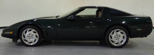
after the first few mods I did to my 1985 corvette (swapping to a 11:1 compression 383, short block, ported trickflow twisted wedge heads and swapping in a crower 00471 roller cam) it ran like crap, because the OEM 24 lb injectors could not keep up with the demand for fuel at much over about 4000 rpm, even with the stock TPI intake in place, and the stock fuel pump would supply about 40 psi at idle but by 4000 rpm pressure dropped to only about 35 psi.
340 lph-90 gph that easily support 650-700 hp
obviously larger than stock flow rate injectors will be required
most systems would be set to run 80% max injector pulse ,
duration.
so you could in theory support up to 8 52 lb injectors,
but something closer to 600 hp and 48 lb injectors ,
would be more reasonable as a goal
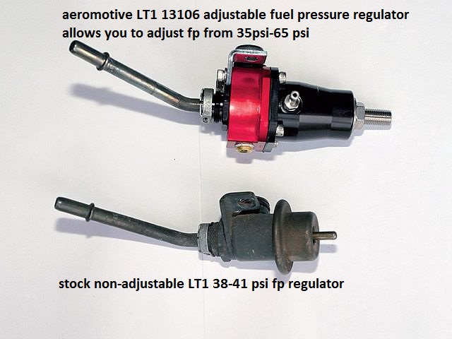
installing ADJUSTABLE EFI fuel pressure regulators, which are a darn good idea on the older C4 corvettes
https://www.ebay.com/itm/DeatschWerks-9-401-1044-415lph-in-tank-Fuel-Pump-For-1985-97-Ford-Mustang-Cobra/164209613855?_trkparms=aid=1110006&algo=HOMESPLICE.SIM&ao=1&asc=228427&meid=18568e4d660a45c08c11ed00a83999a1&pid=100005&rk=2&rkt=12&mehot=pf&sd=113856256792&itm=164209613855&pmt=1&noa=0&pg=2047675&algv=SimplAMLv5PairwiseWebWithBBEV2bDemotion&brand=DeatschWerks&_trksid=p2047675.c100005.m1851
450 lph-119 gph that easily support 950 hp
obviously larger than stock flow rate injectors will be required
most systems would be set to run 80% max injector pulse ,
duration.
so you could in theory support up to 8 66 lb injectors,
but something closer to 600 hp and 64 lb injectors ,
would be more reasonable as a goal
and btw the stock OEM wiring, for the in tank fuel pump, works just fine with the 450LPH aftermarket fuel pump.
in an ideal world all the automotive wiring would be significantly larger gauge than it generally is,
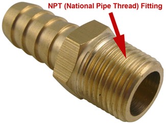
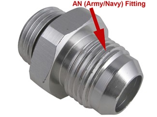
and the fuel lines would be AN#8 (1/2") vs AN#6 (3/8")
but I've had no issues installing several electric aftermarket fuel pumps,
using the existing wire harness in c4 corvettes,
obviously if you have the time and skills upgrading the wire gauge feeding the pump to 12 ga or 10 ga wire,
would reduce the resistance ,
but its not proven to be a weak point so far.
keep in mind fuel pumps and the wiring are not running constantly and sloshing fuel tends to keep the components cool,
Id also point out keeping your fuel tank at least 1/3-1/4 full and throwing 4-5 oz of marvel mystery oil into each full fuel tank, is a proven way to increase fuel pump durability
450 LPH EFI FUEL PUMP
no that slightly larger capacity fuel , pump will work ok, in a stock or modified c4 corvette, keep in mind the pump provides fuel flow, the fuel pressure regulator provides a resistance too that flow, the restriction to flow provides back pressure, if the pump can provide a slightly higher flow than stock it simply has to work less and has slightly less chance of over heating or wear issues.
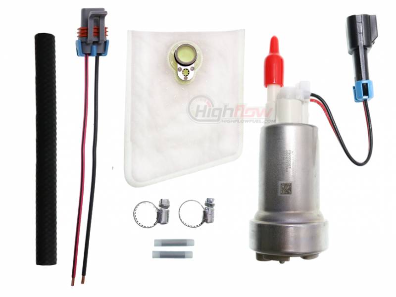
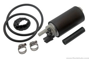
my 1996 corvette had a significantly higher flow capacity in tank fuel pump for several year's plus and it runs much better than it ever did with the stock pump. btw,be sure you install pump pre-filter, that as it keeps micro trash out of the fuel pump

its a soft flexible micro filter, that comes with the fuel pump, that easily fits into the tank, upper opening, , its an in tank fuel permeable screen that easily bends and returns to its intended size & shape, not an issue
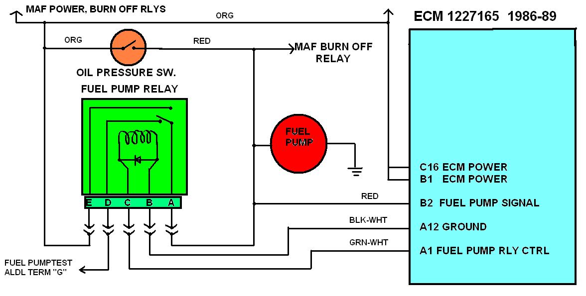
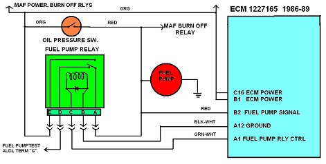
[ "ecss"]The fuel pump relay will be enabled by the ECM when you turn the ignition On for
about 2 seconds. It will also enable the relay if it sees distributor reference pulses
which indicates the distributor is rotating either because the engine is cranking
by the starter or the engine is running.think logically, take it step-by-step!
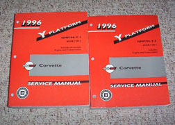
you really need a shop manual for YOUR YEAR CORVETTE.
IT REALLY TENDS TO HELP IF YOU CAN ACCURATELY DIAGNOSE THE PROBLEM BEFORE YOU STAR REPLACING PARTS
http://garage.grumpysperformance.com/index.php?threads/c4-c5-corvette-trouble-codes.2697/#post-51440
http://garage.grumpysperformance.co...ystem-trouble-shooting-flow-chart-info.11536/
http://kinsler.com/index.php/pumps/electric-pumps
http://www.ebay.com/itm/DeatschWerk...rvette-5-7L-/221684142897?hash=item339d679331
http://garage.grumpysperformance.com/index.php?threads/replacing-a-c-4-fuel-filter.1470/#post-3304
http://www.lingenfelter.com/mm5/mer...de=L760070000&Category_Code=C416#.Vj0DUb_O3m0
the most important and effective performance asset you have is simply your ability to ask yourself questions, the ability to think logically isolate and test components carefully and doing the research if its required to find the best answer's you'll need.
OWNING A CODE SCANNER , and a MULTI METER HELPS
first verify the fuel pump is getting the voltage it requires, get out a multi meter and use the link above, if the pumps ARE bad theres a very good chance the fuel in the tank is contaminated with alcohol,rust or water and you need an in tank pre-filter
a logical step by step approach will lead you to the problem, youll be amazed at what youll learn reading links. use of a shop manual and multi meter can be very helpful
RULE#1
never assume a damn thing ISOLATE ,TEST AND VERIFY
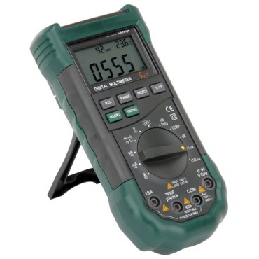
http://www.harborfreight.com/5-in-1-digital-multimeter-98674.html
If you have 12 volts on pin A of the relay that 12 volts goes to the FP fuse and
then the 12 volts goes to the fuel pump.
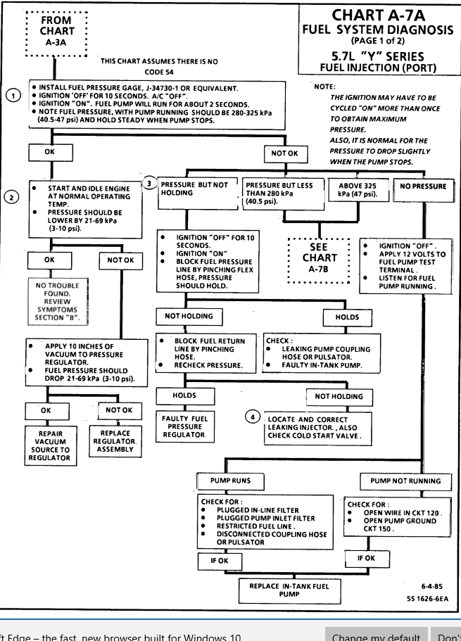
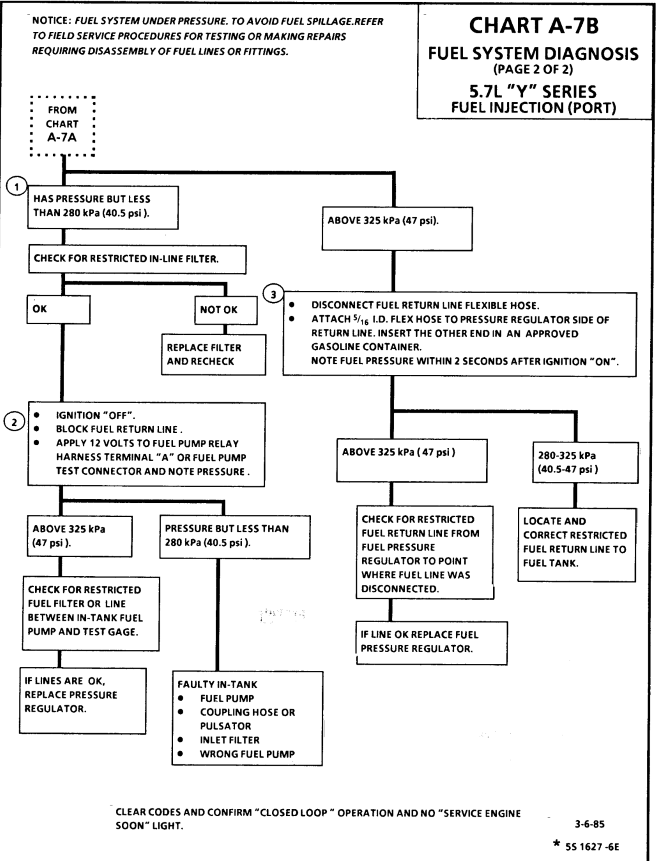
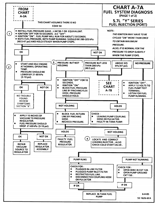
http://www.chevythunder.com/fuel_system_diagnosis.htm
http://members.shaw.ca/corvette86/FuelSystemDiagnosis.pdf
http://www.lingenfelter.com/mm5/mer...de=L760070000&Category_Code=C416#.Vj0DUb_O3m0
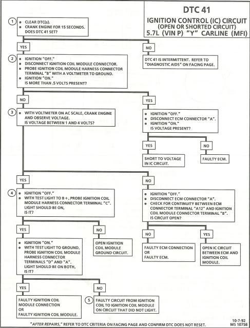
http://www.chevythunder.com/fuel_pump_diagnosis_chart.htm
http://www.chevythunder.com/fuel_system_diagnosis.htm
http://www.chevythunder.com/fuel_pump_code_54.htm
http://www.chevythunder.com/Flow chart index.htm
If you want to test the fuel pump manually, you can apply 12 volts direct to pin G on the
diagnostic connector above the drivers right knee. The 12 volts goes thru the
normally closed contacts of the fuel pump relay to the fuel pump fuse and then
to the fuel pump motor.

where is fuel pump test terminal on 1996 corvette located??
GM replacement sending unit. ACDelco part FLS1099
http://tech.corvettecentral.com/2011/01/c4-diagnostic-trouble-codes/
ITS A GOOD IDEA TO ALWAYS REPLACE THE FUEL FILTER WHEN THE PUMPS REPLACED
The fuel pump should turn on and stay running.
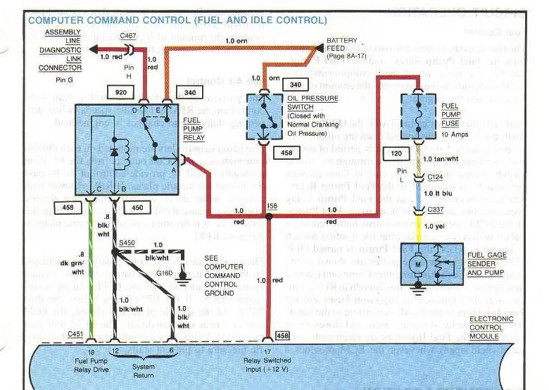
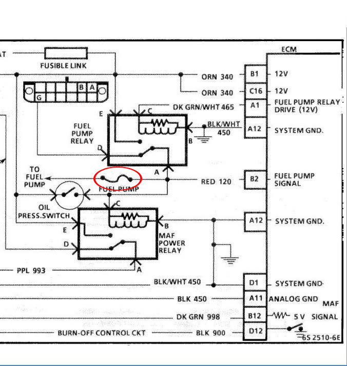
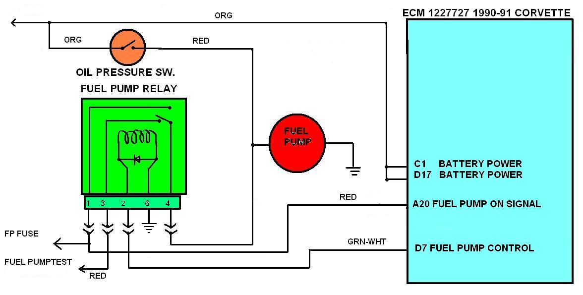
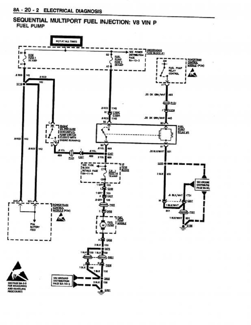
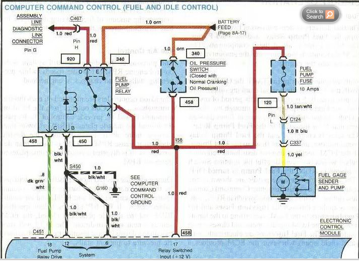
Here's the schematic, of a 1995 corvette fuel pump control. posted below,
save it and print it out.
There are two sources to power the fuel pump.
The PCM enables fuel pump relay #1
As long as the engine is running or cranking.
Otherwise when you turn the ignition on it only enables the relay to provide the fuel pump power for a couple of seconds,
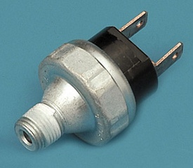
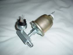
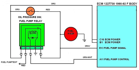
Other source is if the oil pressure switch located next to the rear of the intake ,if the oil pressure is above around 3 psi, 12 volts from fuse ECM Fuse#1
will provide 12 volts to the FP1 fuse#14 which goes to the fuel pump connector Gray wire.
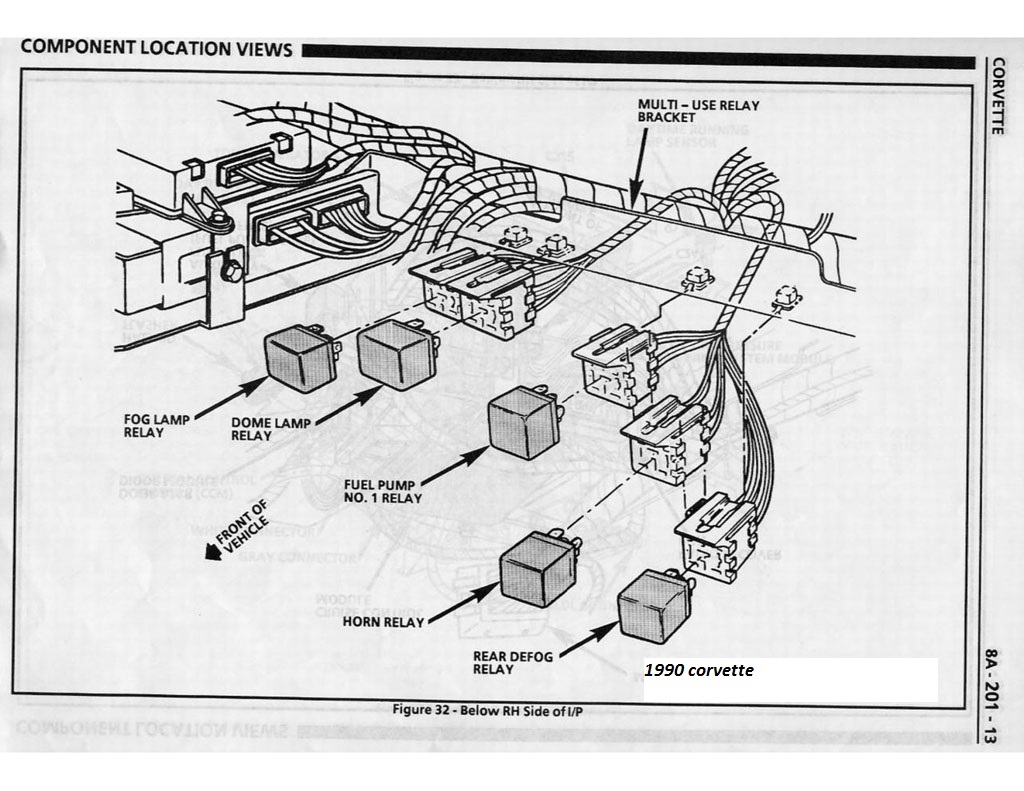
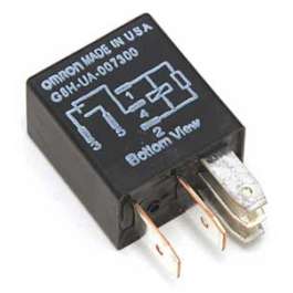
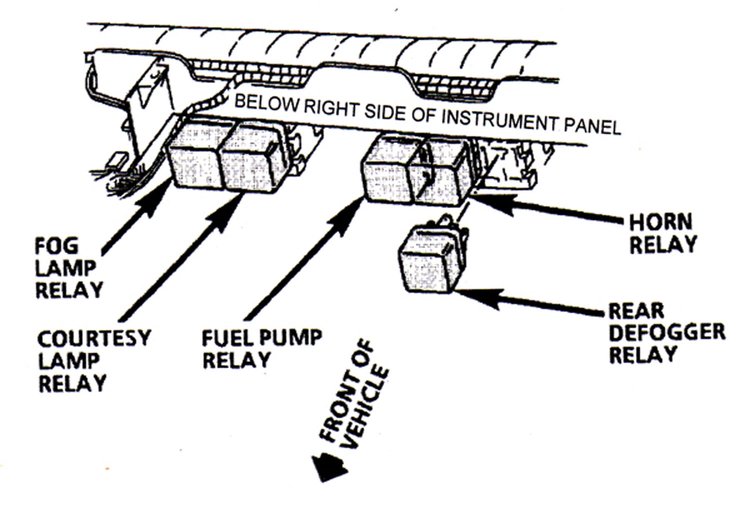
Fuel pump relay #1 is located along the passenger side front edge of the dash. All of the relays
are the same so you can swap them around. Fuel pump relay #2 is used for the LT5 so it
may not be there.
Posted by Hooked on Vettes
Here's the schematic for a 95. I'd think 96 would be the same.
The fuel pump relay is located under the passenger side front edge of the dash. There should be 5 relays.
Relay A for the Horn
Relay B for Fuel Pump #1
Relay C Probably not used. (In 95 used for ZR1 2nd fuel pump)
Relay D for Fog Lamp
Relay E for Courtesy Lamp
Socket F empty not used
The relays on the passenger side wheel well are for the AC Clutch,
and High/Low blower speed relays if you have manual AC (C60).
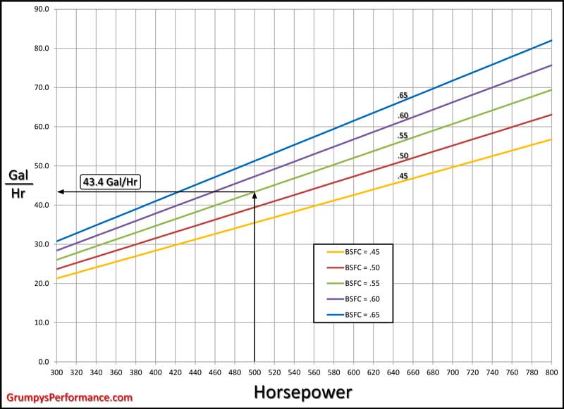
FUEL LINE SIZE Fuel line size is determined by the horsepower of the engine. Up to 350 HP 5/16" or 4AN Up to 500 HP 3/8" or 6AN Up to 700 HP 1/2" or 8AN Up to 1200 HP 5/8" or 10AN RETURN LINE SIZE Return line size is determined by the output of the fuel pump. Up to *29 gal/hr (110 liters/hr) 1/4" or 3AN Up to *45 gal/hr (170 liters/hr) 5/16" or 4AN Up to *90 gal/hr (340 liters/hr) 3/8" or 6AN Up to *180 gal/hr (680 liters/hr) 1/2" or 8AN *Pump output @ 45psi PUMP SIZE Pump size is determined by the horsepower of the engine. Horsepower x .083 = gallons per hour @ 45 psi Example: 500hp x .083 = 42 gal/hr or Horsepower x .314 = liters per hour @ 45 psi Example: 500hp x .314 = 157 liters/hr NOTE: add 25% to pump size for supercharged applications.
HERES A FAIRLY NEW ,AND VERY INTERESTING ADDITION TO THE POTENTIAL FUEL SYSTEM DESIGN, as IT INCREASES THE FUEL PUMPS ABILITY TO ACCESS FUEL
http://www.motoiq.com/MagazineArticles/ ... rvoir.aspx
ROCK AUTO HAS FUEL PUMPS THAT DON,T COST NEARLY AS MUCH AS MOST AUTO PARTS STORES< BUT KEEP IN MIND BRAND NAME PUMPS TEND TO LAST LONGER THAN BARGAIN BASEMENT PRICE CHINESE IMPORT CRAP
http://www.rockauto.com/catalog/raframe ... nih4detdi1
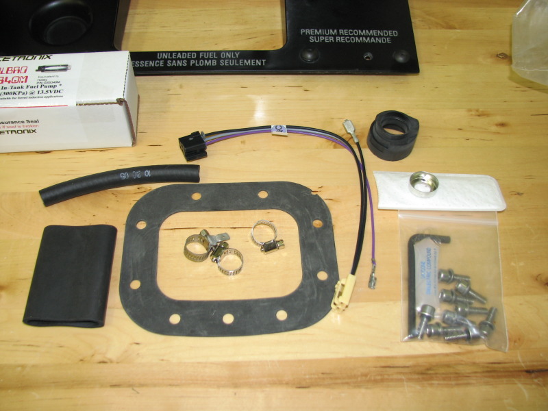
THERES A BIG DIFFERENCE IN PURCHASING A COMPLETE ASSEMBLY OF MATCHED COMPONENTS FOR $250
vs a BARGAIN BASEMENT PUMP OF UNKNOWN QUALITY FOR UNDER $30
http://www.racetronix.biz/customkititems.asp?kc=FPA-010H
viewtopic.php?f=55&t=10536&p=44732&hilit=holley+fuel#p44732
I bought and have used the BOSCH PUMP, but theres better options available now than there were 12 years ago, ID suggest a 300-350 lph pump with AN#8 lines , and fuel filter on an engine that is intended to produce north of 500hp,
http://garage.grumpysperformance.com/index.php?threads/replacing-a-c-4-fuel-pump.33/
http://members.shaw.ca/corvette86/FuelSystemDiagnosis.pdf
http://www.thecalculatorsite.com/conversions/liquidvolume/liters-to-gallons-(us).php
A common upgrade that frequently works on C4 corvettes but its marginal on a serious race engine in my experience, especially if used with stock fuel lines and filter.
http://www.summitracing.com/parts/vpn-gca758-2/overview/
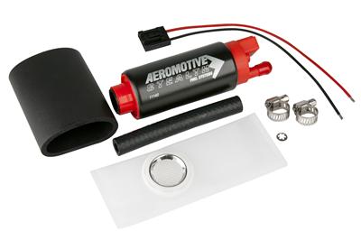
heres a pump I find works well with AN#8 lines and filters
http://www.summitracing.com/parts/aei-11169
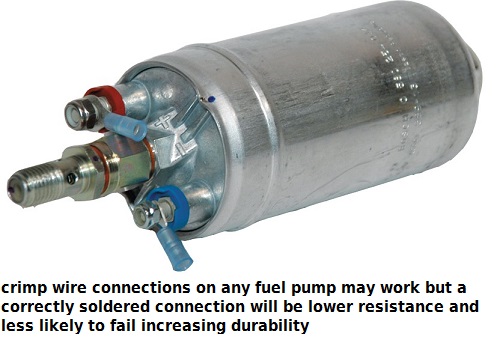
Bosch High Pressure Pump in the tank replacement fuel pump in my 1985 vette when the original pump failed, and yes after helping others install the cheaper knock-offs I think theres a difference in quality,and while the price is higher and there are other options, I would at least consider the better brand name pumps, rather than the less expensive knock-offs.
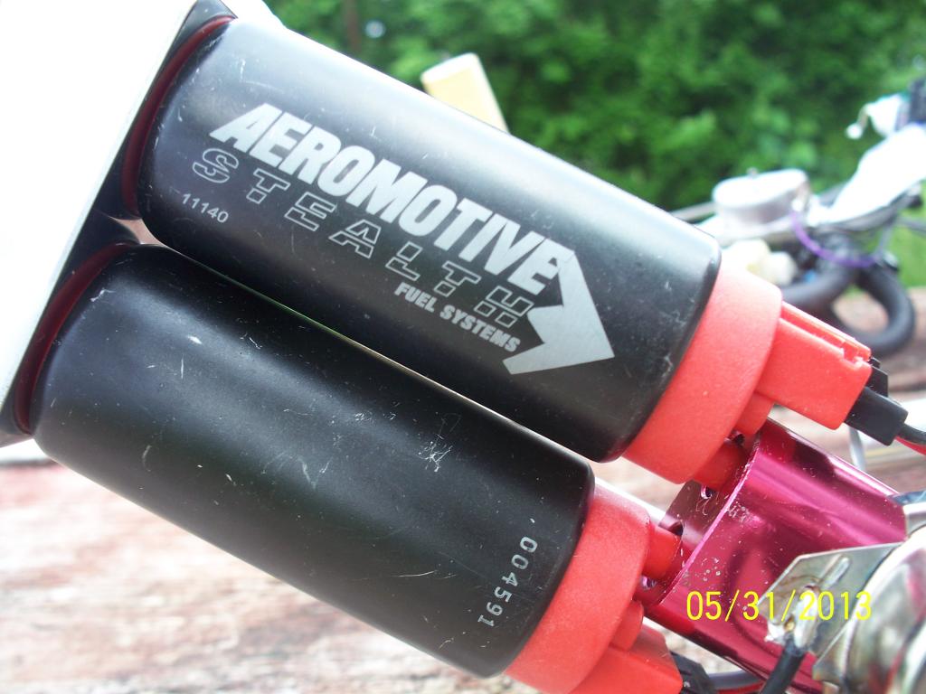
if you look at places that sell BOTH good quality and bargain priced parts like ROCKAUTO or SUMMIT OR JEGS, youll see theres fuel pumps available from under $30 to over $250 PLUS aftermarket sources can go up from there, theres no way that a fuel pump from a well known manufacturer like lets say BOSCH aeromotiveinc or WELBRO that sells for 8 times what the bargain basement pump is going to be made to the same quality or contain the same attention to detail or have similar component quality, you tend to get what you pay for
http://members.shaw.ca/corvette86/FuelS ... gnosis.pdf
http://www.weldonracing.com/product/64/ ... _Pump.html
first check your shop manual for the fuse and fuse able link locations
fuses are located in several locations and fuse-able links near the battery
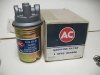
Bosch High Pressure Pump 0-580-254-984
Rated at 44 GPH @ 90 PSI 750+ Hp This pump is identical to the Accel part number 74702 which they boast will handle 870 Hp!
http://www.lucasinjection.com/bosch_and ... _pumps.htm
http://www.expressfuelpumps.com/
http://www.boschfuelpumps.com/
http://www.caspeed.com/boschpump/boschpump.html
the fuel pump has a 12 volt 15 AMP fused circuit
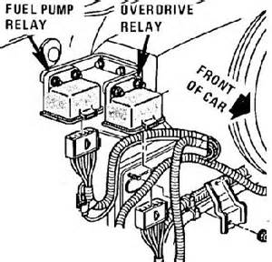
Under the hood--to the right of the blower motor---should be 2 relays---fuel pump is the one farthest to the right.
theres a good deal of good and useful advise, in this thread but Id point out the
sensor(s) next to the distributor, base ,could be a cause of a problem, because occasionally one of these starts acting up intermittently causing the fuel pump or ECM to stop working,or the VATS system, or the FUEL SUPPLY SYSTEM.
READ THRU THIS LINKED INFO
http://www.joby.se/corvette/mods/2001-0X07_fuelpump/
heres some other possibility,s
http://members.shaw.ca/corvette86/FuelS ... gnosis.pdf
http://www.eurovettes.com/c4_faultcodes.htm
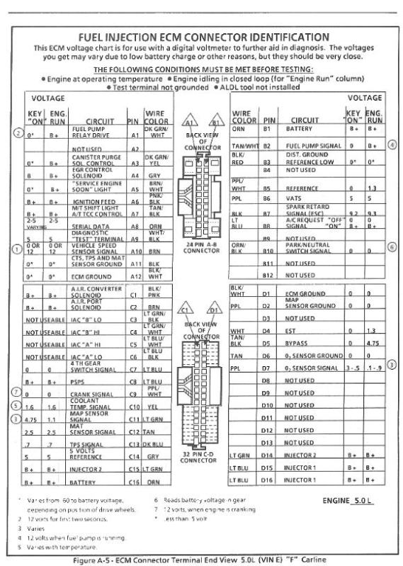
http://chevythunder.com/fuel injection ecm pinouts.htm
http://garage.grumpysperformance.com/index.php?threads/installing-a-fuel-cell.733/#post-3532
read thru these threads also, as theres a good deal more related info in those threads and links
obviously the first step is PROVING its the FUEL PUMP ITSELF THAT NEEDS REPLACEMENT AND NOT A FUSE OR RELAY OR SENSOR SO READ THRU THESE SUB LINKS, and DO A FEW TESTS BEFORE JUST ASSUMING ITS A DEFECTIVE FUEL PUMP,
If the ECM sees oil pressure greater than 4 PSI and the reference pulses from the distributor, it will energize the injector drivers
The ECM will also pull in the fuel pump relay in effect paralleling it electrically with the oil pressure switch.
(If the fuel pump relay fails, you can still normally get the car to start and run unless you can,t make at least 4 PSI oil pressure. This is a limp home mode feature put in place to allow for a fuel pump relay failure).
viewtopic.php?f=32&t=596
http://www.corvette-guru.com/modules/ne ... post129791
its not necessary to drain the tank but its a good idea to do so.
IT IS NECESSARY TO DISCONNECT THE BATTERY READ THAT AS ABSOLUTELY MANDATORY during the swap procedure to prevent any chance of accidental problems
step one have the parts on hand PLUS 3 ft of 3/8" fuel line and 1 ft of 5/16" fuel line , I know, you may not need the fuel line but in many cases its faster and easier to remove the old line and replace with new ones
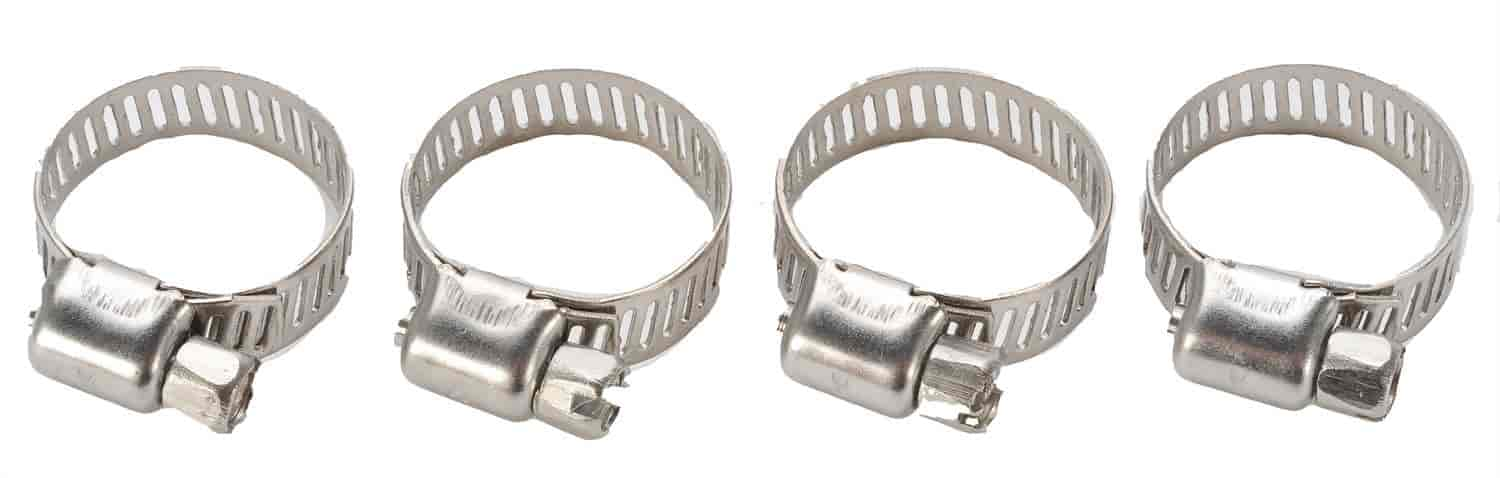
hose clamps, youll want several 1/2" size for the lines
fuel pump
http://www.ecklers.com/product.asp?pf_id=30666&dept_id=1277
fuel pump screen
http://www.ecklers.com/product.asp?pf_id=30668&dept_id=1277
fuel filter
http://www.ecklers.com/product.asp?pf_id=A3479&dept_id=1303
(optional but a GREAT IDEA)
ok, step one,
make darn sure the keys are out of the car and the battery is disconnected for extra safety
step two, open the fuel fill door center rear deck where you normally fill the car and remove the gas cap
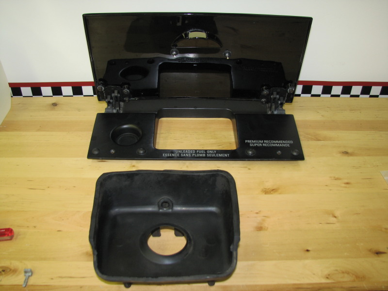
step three
remove the four very small torx screws in the corners and lift off the door assembly
step four
theres a rubber bib fuel spill tray)(around the fill spout, remove the gas cap and work the bib fuel spill tray ) (out , and disconnect the water drain line and label it with masking tape/pen
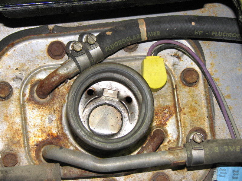
step five
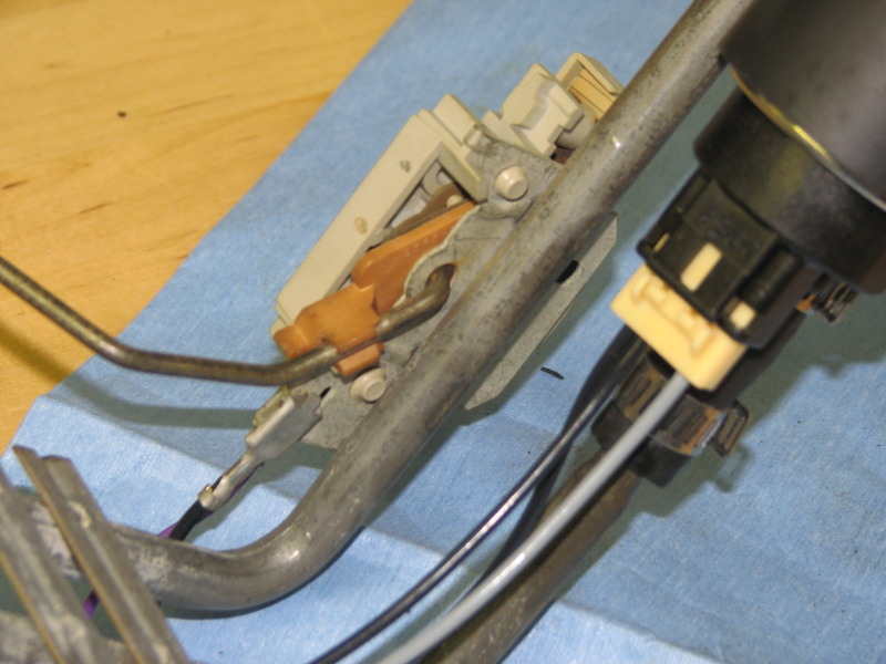
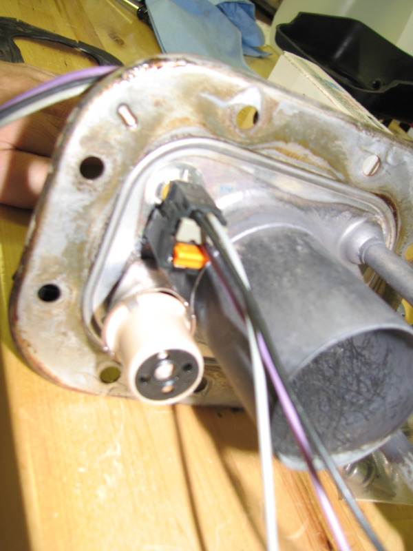
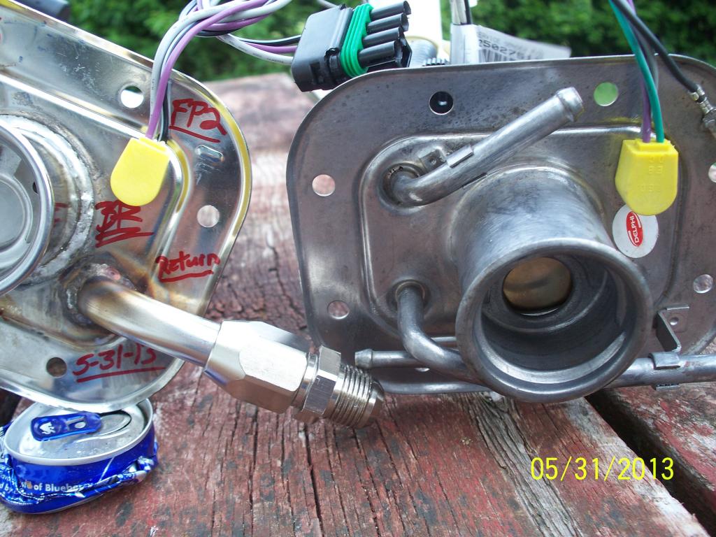
label the three lines with masking tape/pen (upper line/lower line /left side line)
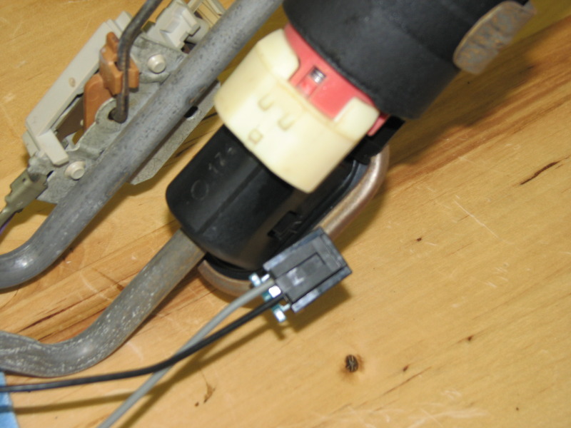
remove each at the central point in the opening, then disconnect the electrical connector on the lower edge of the opening
step six
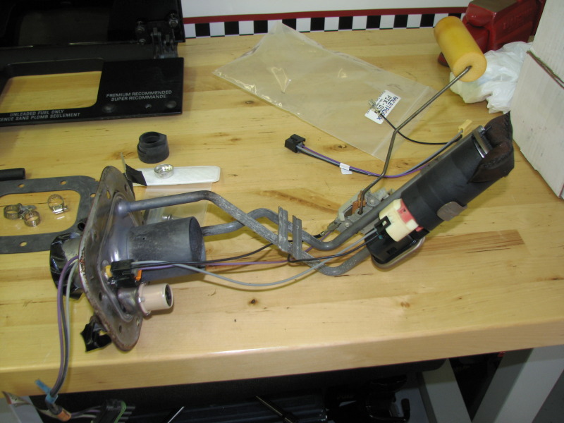
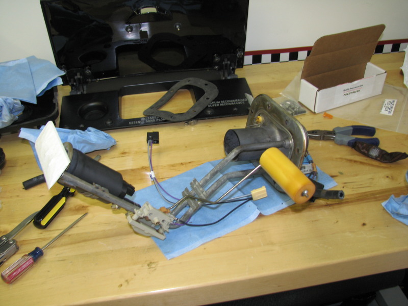
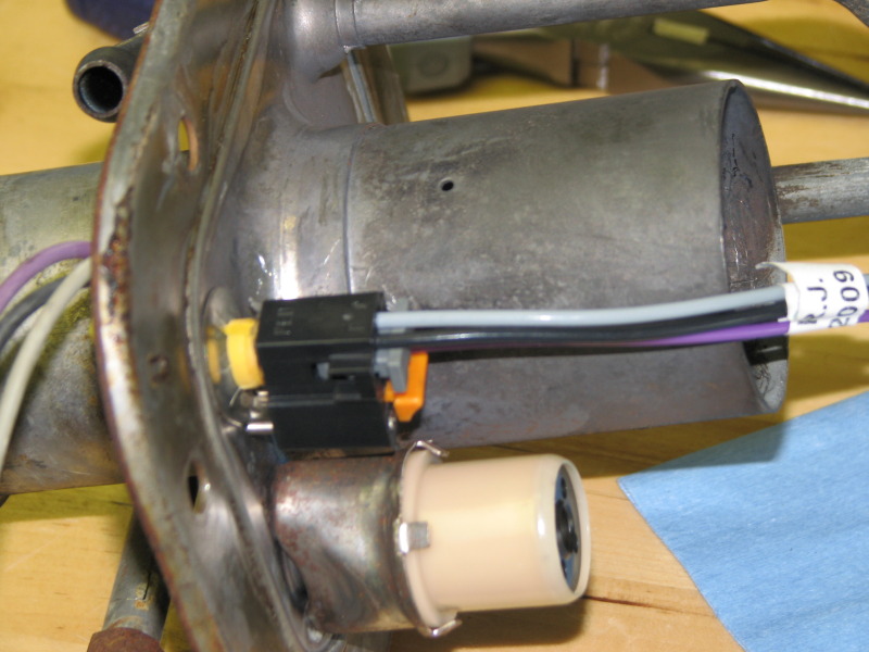
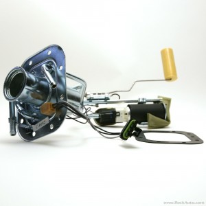
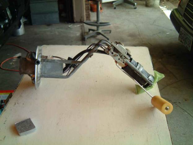
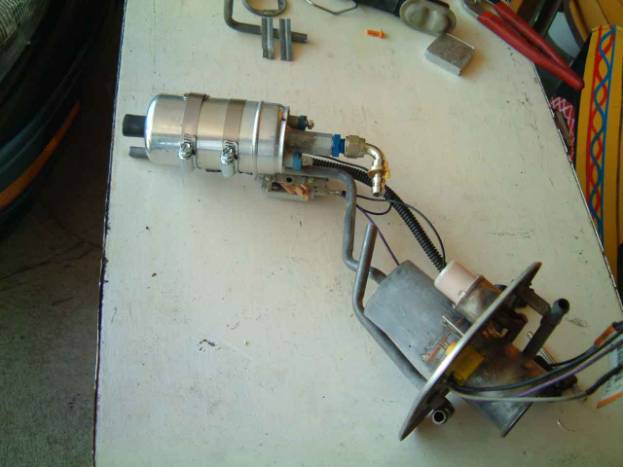
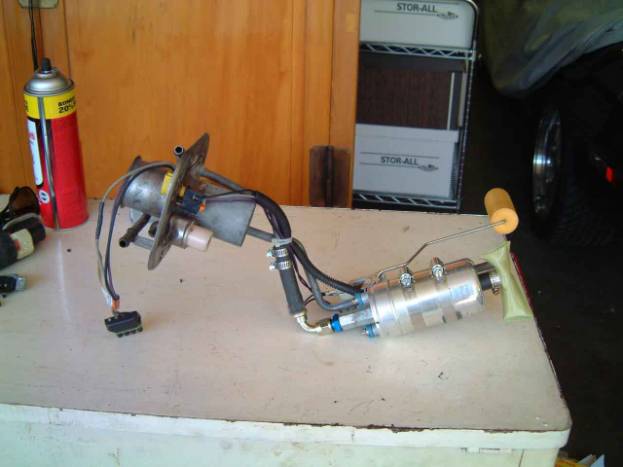
remove the 8 10mm bolts and look carefully at where the components go, after they are removed the pump lifts up and out, the pump normally comes with instructions also, but its fairly simple, the pump, lines and fuel level sensor lifts out as a sub assembly, look thru the link below for pictures and more info
the stock pump puts out less than 60 gallons an hour
http://aeromotiveinc.com/tech-help/freq ... uel-pumps/
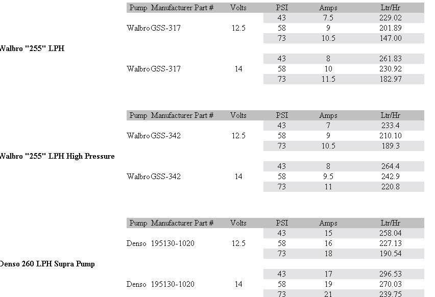
340 liters per hour flow should be good for/ approximately 700HP (thats approximately 90 gallons an hour
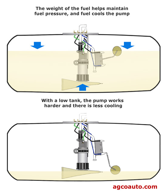
just a bit of related info that may or may not apply in your case, electric in tank fuel pumps are COOLED by both sloshing fuel and fuel flow rates and are DESIGNED to be used with a return style fuel pressure regulator, use with a nearly empty fuel tank or with a dead head style fuel pressure regulator will DRASTICALLY reduce the pumps life expectancy
http://www.racerpartswholesale.com/prod ... And_Wiring
heres a 200 gallon an hour rated pump that should easily supply over 1000hp, but youll need AN#8 or larger fuel lines
http://aeromotiveinc.com/wp-content/upl ... _guide.pdf
BTW RELATED THREADS
the fuel pump has a 12 volt 15 AMP fused circuit

http://store.summitracing.com/parts/aei-11169
http://forum.grumpysperformance.com/viewtopic.php?f=55&t=635
http://forum.grumpysperformance.com/viewtopic.php?f=55&t=211
http://forum.grumpysperformance.com/viewtopic.php?f=55&t=1200
http://forum.grumpysperformance.com/viewtopic.php?f=55&t=3165&p=8442#p8442
"I have replaced countless in tank fuel pumps. In tank fuel pumps are submerged in fuel in order to help them run cooler. I see many people out there (especially with today's gas prices) who run their vehicles on the empty side of the tank. Empty tank=hot pump. It's just as easy to keep the top half filled as the bottom half. Keeping adequate gas in the tank in conjunction with a regular filter change will insure your pump will last it's longest."
http://www.joby.se/corvette/mods/2001-0X07_fuelpump/
NOW IF YOU WANT TOO UPGRADE HERES A MORE USEFUL LINK WITH PART NUMBERS
http://www.caspeed.com/boschpump/boschpump.html
http://www.racetronix.biz/customkititem ... A-010H&eq=
255 liters per hour flow should be good for/ approximately 500HP
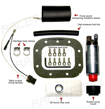
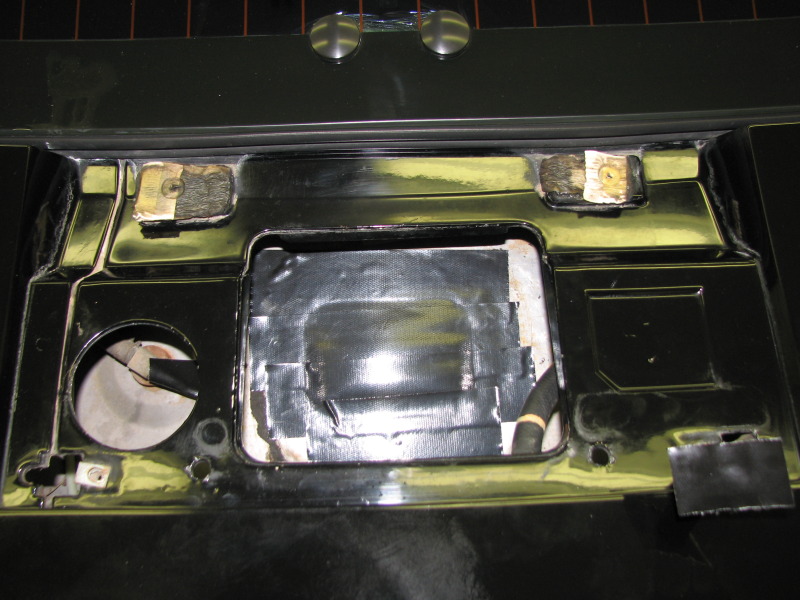
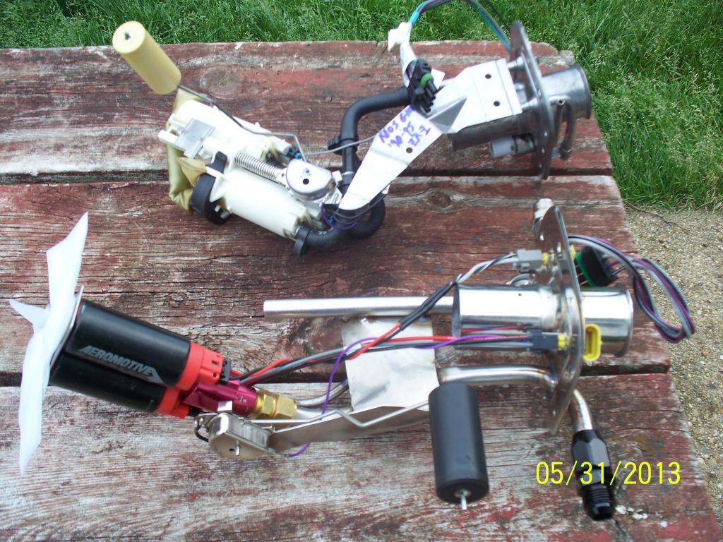
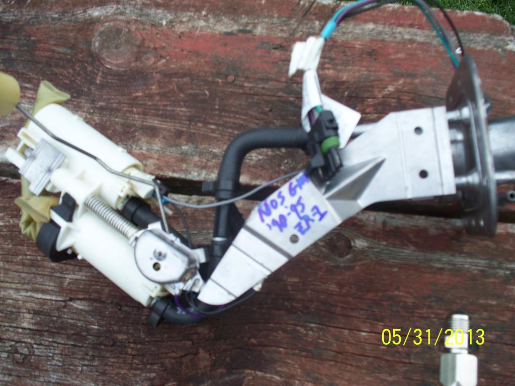
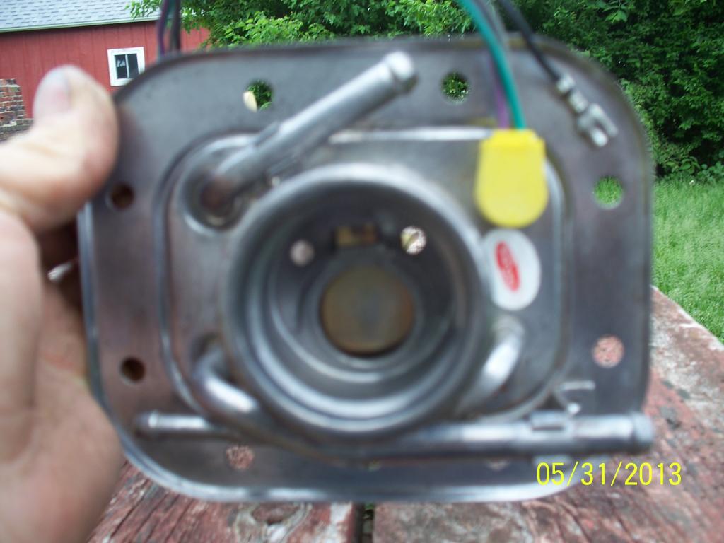
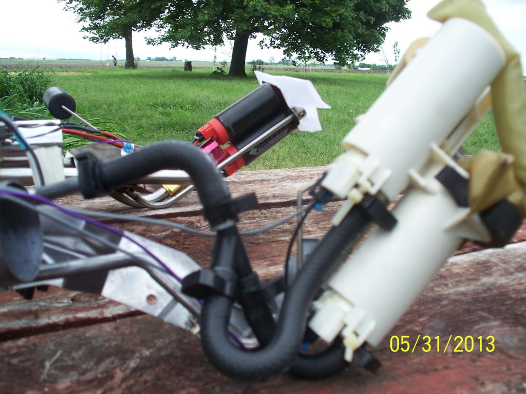
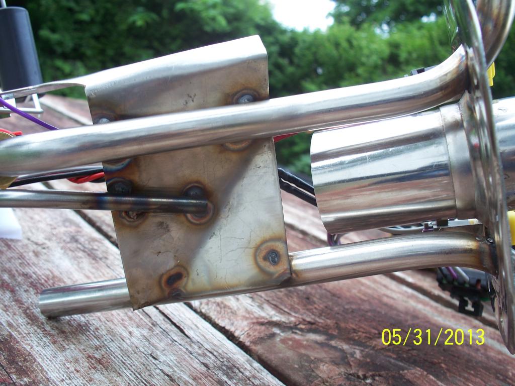
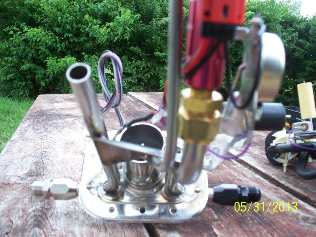
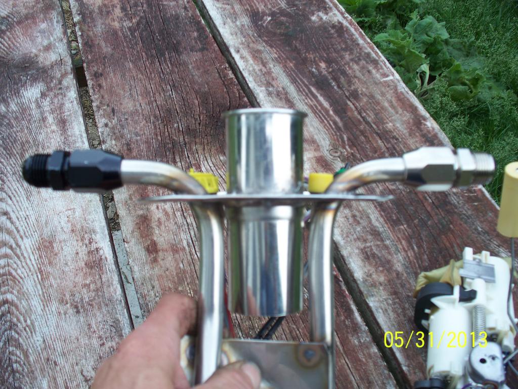
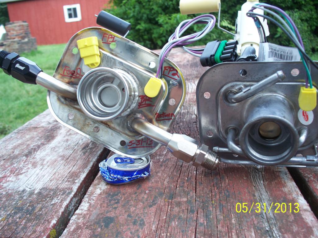
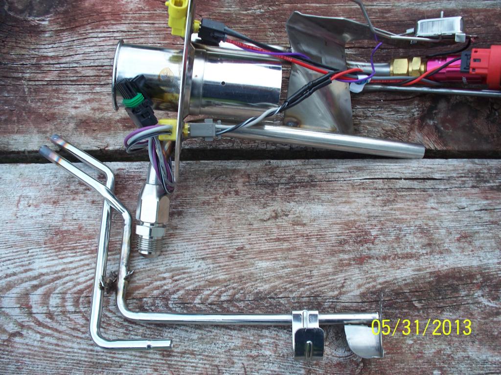
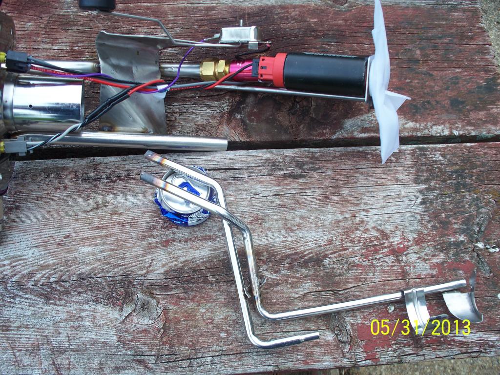
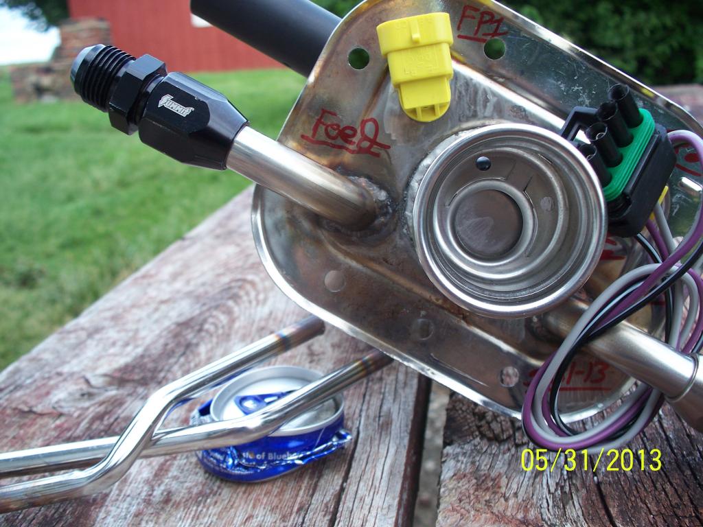
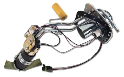
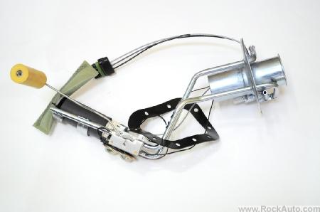
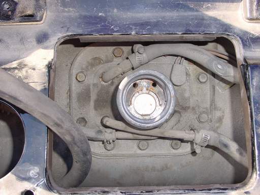
access to the fuel pump is thru the panel around the tank fill cap SIMILAR TO THIS, held in place with 10mm bolts in this picture
label the fuel return lines before you disconnect them to insure replacing them correctly
https://www.ecklerscorvette.com/corvette-gas-tank-filler-neck-seal-1984-1996.html
Fuel Pump
http://boschfuelpumps.com/
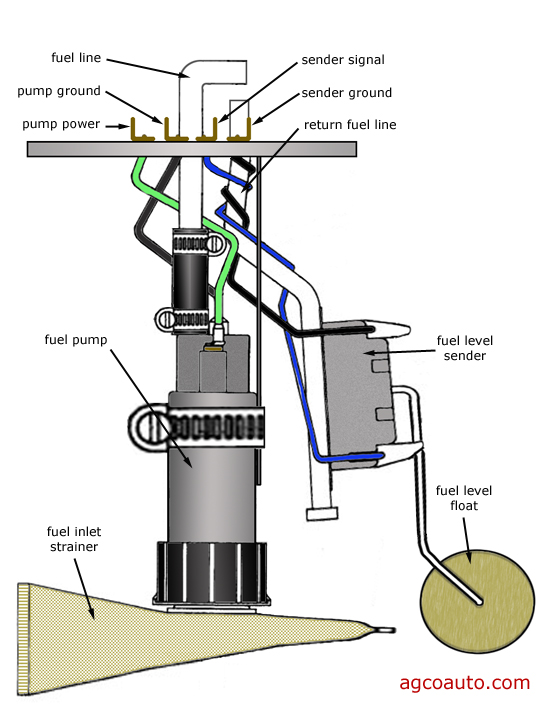
In a C4 Corvette, the fuel pump is one of those crossover items that is part of both the electrical system and the fuel system. The pump is a submerged variety, electrically operated, contained in the fuel tank and somewhat difficult to get to.
Although the pump is difficult to physically check, you can make certain that it at least runs by turning the ignition switch to on (but don't start the engine).
If the pump motor is working, you will hear a whirring noise coming from from the rear of the vehicle that will last for 2 seconds. Note that this does not prove that the pump is actually pumping fuel in sufficient quantity and/or pressure but it does prove if the pump motor itself is operating.
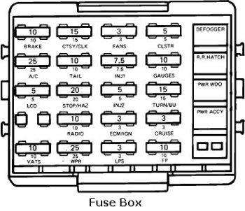
If you do not hear any sound, check the fuse labeled "Crank" on the fuse panel.
If the fuse is not blown but there is no sound from the tank area, there is a problem with either the motor or the wiring feeding the fuel pump motor.
If the pump appears to be working, you will need to measure the fuel pressure at the Shraeder valve located on the fuel rail on the engine. Anything below 35 PSI is cause for alarm and can be the fuel pump (pumps---2 each---on a ZR-1), the fuel pressure regulator, the check valves in the fuel return line, the fuel filter or a obstructed fuel line.
Once you have troubleshooted your Corvette’s Fuel System and determined it is time to install a new fuel pump & sending unit on your Corvette you will first need to disconnect the negative battery cable and relieve the pressure in the fuel system. To relieve the fuel system pressure on a C4 Corvette you can simply remove the gas cap and let the car sit for 15 minutes. Once the pressure is relieved drain your Corvette’s fuel tank and remove the tank filler door attaching screws and bezel. Next, lift the fuel tank filler pipe housing and disconnect the drain hose from the nipple. Before disconnecting the fuel tank filler pipe housing, clean all fuel connections and surrounding areas to avoid contaminating the fuel system. Next disconnect the fuel hoses and EVAP hose from the fuel sender assembly. Plug or pinch the fuel feed and return hoses and remove the fuel sender electrical connector. To finish removal of your C4 Corvette’s fuel pump and sending unit remove the fuel sender assembly attaching screws, assembly, and gasket. You can re-install the old gasket but first check to see if your new C4 Corvette Sending Unit came with a new gasket. If it did then discard the gasket and thoroughly clean the gasket sealing surfaces. If you just purchased a new C4 Corvette Fuel Pump you will need to purchase a gasket separately or re-install the old gasket. Finally, cuts, nicks, swelling, or distortion is common on the fuel feed, fuel return and EVAP hoses so be sure to inspect these hoses before proceeding.
Once you are ready to install your new C4 Corvette Fuel Pump & Sending Unit begin by positioning the gasket on the fuel tank with the notch facing forward in the right hand corner of the tank. Carefully fold the strainer to allow it to fit through the opening in the tank. Next, install the fuel sender assembly into the fuel tank and re-connect the fuel sender electrical connector. Then connect the EVAP hose and tighten the hose clamps. Re-connect the fuel drain hose to the nipple on the filler pipe housing and place the housing around the filler pipe. Now you can re-install the filler door bezel, add fuel, and re-connect the negative battery cable. Before driving your Corvette away, be sure to turn the ignition switch on, off, then back on and check for any possible fuel leaks. If no leaks are recognized your Corvette fuel pump replacement was a success.
the answer to how big a fuel pump yoou need or what injector size is required or what fuel pressure level will be necessary is a predicable value and it depends on what power range your dealing with and what your trying to supply with fuel and the rate its potentially using that fuel, the stock fuel pump will easily supply 400hp plus on a c4 corvette or a bit more and the stock injector size won,t
it takes (X) amount of fuel/air mix at about a 13:1-14:1 ratio being burned per minute to make (Y) amount of HORSEPOWER
you can spin a small engine fast or a big engine slower but it will take a certain amount of fuel being consumed to produce a power level and its reasonably predictable at about a BSFC of about .5-.55, you might be amazed at what you can learn reading thru the linked info on the site.
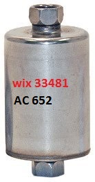
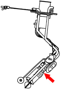
the fuel filters located under the front pass side door area near the frame and the shop manual will go into some detail on its removal, yes your going to loose some fuel so its best to do this up on a lift or jack stands where access is easier and where you can see what your doing.
theres an arrow on the filter indicating direction of fuel flow for a reason , pay attention and do it correctly, have some shop towels and a fire extinguisher handy ANYTIME you work on fuel lines!
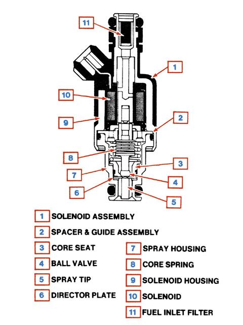
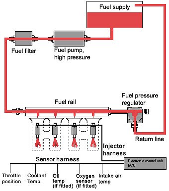
Fuel System
The TPI Fuel System comprises the following components:
In the original GM applications, the fuel injection pressure pump is installed inside the vehicles fuel tank. Adapting this pump has never seemed to us a practical solution, unless you are installing the TPI system on a vehicle that utilises the stock GM gasoline tank. This would allow for the installation of an internal tank type pump. If you are installing the TPI system into a vehicle that was originally equipped with carburettors, or even a throttle body fuel injection system, it WILL be necessary to install a compatible high pressure port fuel-injection type pump. Any number of fuel pumps will serve the purpose. We can recommend the fuel pump from a 78-80 and 82-85 Datsun 280Z. The Nissan part number for this pump is 17011-P7211. In addition, these pumps are usually readily available from wrecking yards, as are similar units from BMW, Mercedes Benz, Jaguar and many other late-model port-injected vehicles.
The electric fuel pump used should be capable of maintaining at least 50 psi under full throttle, and a return line MUST be plumbed back to the fuel tank/tanks if there is not one installed on the car!
IF THE FUEL TANK IN YOUR VEHICLE DOES NOT HAVE PROVISION FOR A RETURN LINE, IT IS NOT NECESSARY TO MODIFY THE TANK!
By installing the appropriate size tee-fitting into the fuel supply line from the tank to the inlet side of the fuel pump and connecting the return line into this suction line at the newly installed tee, the need for a return line can be met without removing and modifying the fuel tank.
If you are installing your TPI system in a vehicle which was originally equipped with a carburetted engine and a mechanical fuel pump that was equipped with a factory installed return line, BE AWARE, that many of these systems have a restriction in the return line. This restriction should be removed to eliminate the possibility of unnecessarily high pressures in this portion of the fuel system. These restrictions are often contained in the return line fitting on the gas tank sending unit mounting flange. If it is inconvenient to access this flange to remove the restriction, the return line can be re-routed to the fuel pump inlet line, as described above.
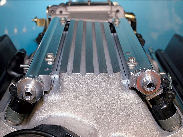
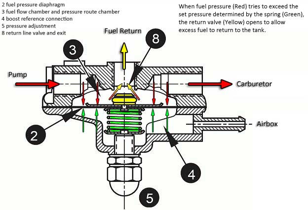
Fuel Regulator
A fuel pressure regulator is mounted on the rear of the right side of the TPI fuel rail. This non-adjustable regulator controls fuel pressure, to maintain it at about 41 psi under high vacuum conditions, such as idle, and up to 47 psi under low vacuum conditions, such as full throttle operation. Adjustable fuel pressure regulators are available through a number of after-market suppliers, for high performance applications.
Fuel Lines
Because of the high fuel pressures involved, we prefer to use braided stainless fuel lines with threaded connectors, as opposed to just using hose clamps and rubber hose, when making the connection between the TPI unit and the fuel pump! The pressure inlet of the TPI system is the fitting with the larger I.D. A return line MUST be connected from the petrol tank to the smaller I.D. fitting. If you are utilising braided stainless hose and fittings, it will be necessary to purchase after-market adaptor fittings which thread into the hose connections, or the TPI manifold, to allow the use of these improved hose and fitting assemblies, since the OEM connections utilise metric threads and O-ring type seals. These adaptor fittings are available, either in a male configuration for installation into the fittings on the fuel rails of the TPI or, into the ends of the stock rubber hoses which attach to the body/frame mounted steel fuel lines that come forward from the fuel tank, or in a female configuration, for installation onto the end of the engine mounted steel tubing extensions, which are a part of all factory TPI fuel line installations.
The above-mentioned items are all that could be considered separate elements of which are component parts of the TPI installation. Simply stated, the system will not work at its designed level of performance if any one of the above items is deleted! The following information will include some additional items which, while not required to make the system functional, are items that are utilised in the factory installation to make everything work as originally designed, and which may be used, as necessary, or deleted if so desired, with no functional effect on the real world operation of the unit.
http://garage.grumpysperformance.co...uick-disconnect-fuel-line-related-info.16693/
http://forum.grumpysperformance.com/viewtopic.php?f=55&t=635
http://forum.grumpysperformance.com/viewtopic.php?f=55&t=211
http://chevythunder.com/fuel injection troubleshooting page C.htm
http://forum.grumpysperformance.com/viewtopic.php?f=55&t=1200
http://forum.grumpysperformance.com/viewtopic.php?f=55&t=3165&p=8442#p8442
YEAH I KNOW YOU WANT TO SKIP OVER AND IGNORE THE SUB LINKS... THAT WOULD BE A MISTAKE!!
my current corvettes 383 combo
I was asked "whats your current engine, combo, Ive listed it below, KEEP in mind the whole concept of the build, a dual personality engine that, the idea was too build an engine combo that would work well N/A, for cruising on highways, with a bit over 440 hp (NA) yet primarily designed too...
garage.grumpysperformance.com
Fuel Pumps │Automotive, Motorcycle, ATV, Powersports Performance and OEM Replacement
The Authority in OEM & Affordable Powersports & Automotive Replacement Parts. Get The Gold Standard of Reliability, Durability & Performance.
www.highflowfuel.com
http://www.highflowfuel.com/i-10388...rainers.html?gclid=COabwduFgs0CFZKGaQodbGQCOw
keep in mind fuel pumps and the wiring are not running constantly and sloshing fuel tends to keep the components cool,
Id also point out keeping your fuel tank at least 1/3-1/4 full and throwing 4-5 oz of marvel mystery oil into each full fuel tank, is a proven way to increase fuel pump durability, no one would reasonably dispute the wisdom of replacing the O.E.M. wiring with stranded 10 ga to reduce the ohms resistance to allow a bigger amp load electric fuel pump , but that is not a mandatory upgrade, with most of the higher flow rate in tank electric fuel pumps, its just a smarter route to take, as it provides a larger safety margin, in that theres hundreds of guys running higher amp fuel tank pumps that have not had issues
after the first few mods I did to my 1985 corvette (swapping to a 11:1 compression 383, short block, ported trickflow twisted wedge heads and swapping in a crower 00471 roller cam) it ran like crap, because the OEM 24 lb injectors could not keep up with the demand for fuel at much over about 4000 rpm, even with the stock TPI intake in place, and the stock fuel pump would supply about 40 psi at idle but by 4000 rpm pressure dropped to only about 35 psi.
340 lph-90 gph that easily support 650-700 hp
obviously larger than stock flow rate injectors will be required
most systems would be set to run 80% max injector pulse ,
duration.
so you could in theory support up to 8 52 lb injectors,
but something closer to 600 hp and 48 lb injectors ,
would be more reasonable as a goal
installing ADJUSTABLE EFI fuel pressure regulators, which are a darn good idea on the older C4 corvettes
fuel pressure regulators
Volume vs. Pressure FUEL Volume and FUEL pressure are two completely different things when you talk about fuel,supplied to an engine, but they must work together to give you the proper air/fuel mixture delivery. Both carburetors and EFI systems require the proper fuel volume to make the desired...
garage.grumpysperformance.com
https://www.ebay.com/itm/DeatschWerks-9-401-1044-415lph-in-tank-Fuel-Pump-For-1985-97-Ford-Mustang-Cobra/164209613855?_trkparms=aid=1110006&algo=HOMESPLICE.SIM&ao=1&asc=228427&meid=18568e4d660a45c08c11ed00a83999a1&pid=100005&rk=2&rkt=12&mehot=pf&sd=113856256792&itm=164209613855&pmt=1&noa=0&pg=2047675&algv=SimplAMLv5PairwiseWebWithBBEV2bDemotion&brand=DeatschWerks&_trksid=p2047675.c100005.m1851
450 lph-119 gph that easily support 950 hp
obviously larger than stock flow rate injectors will be required
most systems would be set to run 80% max injector pulse ,
duration.
so you could in theory support up to 8 66 lb injectors,
but something closer to 600 hp and 64 lb injectors ,
would be more reasonable as a goal
and btw the stock OEM wiring, for the in tank fuel pump, works just fine with the 450LPH aftermarket fuel pump.
in an ideal world all the automotive wiring would be significantly larger gauge than it generally is,
and the fuel lines would be AN#8 (1/2") vs AN#6 (3/8")
but I've had no issues installing several electric aftermarket fuel pumps,
using the existing wire harness in c4 corvettes,
obviously if you have the time and skills upgrading the wire gauge feeding the pump to 12 ga or 10 ga wire,
would reduce the resistance ,
but its not proven to be a weak point so far.
keep in mind fuel pumps and the wiring are not running constantly and sloshing fuel tends to keep the components cool,
Id also point out keeping your fuel tank at least 1/3-1/4 full and throwing 4-5 oz of marvel mystery oil into each full fuel tank, is a proven way to increase fuel pump durability
450 LPH EFI FUEL PUMP
no that slightly larger capacity fuel , pump will work ok, in a stock or modified c4 corvette, keep in mind the pump provides fuel flow, the fuel pressure regulator provides a resistance too that flow, the restriction to flow provides back pressure, if the pump can provide a slightly higher flow than stock it simply has to work less and has slightly less chance of over heating or wear issues.
my 1996 corvette had a significantly higher flow capacity in tank fuel pump for several year's plus and it runs much better than it ever did with the stock pump. btw,be sure you install pump pre-filter, that as it keeps micro trash out of the fuel pump
its a soft flexible micro filter, that comes with the fuel pump, that easily fits into the tank, upper opening, , its an in tank fuel permeable screen that easily bends and returns to its intended size & shape, not an issue
[ "ecss"]The fuel pump relay will be enabled by the ECM when you turn the ignition On for
about 2 seconds. It will also enable the relay if it sees distributor reference pulses
which indicates the distributor is rotating either because the engine is cranking
by the starter or the engine is running.think logically, take it step-by-step!
you really need a shop manual for YOUR YEAR CORVETTE.
IT REALLY TENDS TO HELP IF YOU CAN ACCURATELY DIAGNOSE THE PROBLEM BEFORE YOU STAR REPLACING PARTS
http://garage.grumpysperformance.com/index.php?threads/c4-c5-corvette-trouble-codes.2697/#post-51440
http://garage.grumpysperformance.co...ystem-trouble-shooting-flow-chart-info.11536/
http://kinsler.com/index.php/pumps/electric-pumps
http://www.ebay.com/itm/DeatschWerk...rvette-5-7L-/221684142897?hash=item339d679331
http://garage.grumpysperformance.com/index.php?threads/replacing-a-c-4-fuel-filter.1470/#post-3304
http://www.lingenfelter.com/mm5/mer...de=L760070000&Category_Code=C416#.Vj0DUb_O3m0
the most important and effective performance asset you have is simply your ability to ask yourself questions, the ability to think logically isolate and test components carefully and doing the research if its required to find the best answer's you'll need.
OWNING A CODE SCANNER , and a MULTI METER HELPS
first verify the fuel pump is getting the voltage it requires, get out a multi meter and use the link above, if the pumps ARE bad theres a very good chance the fuel in the tank is contaminated with alcohol,rust or water and you need an in tank pre-filter
a logical step by step approach will lead you to the problem, youll be amazed at what youll learn reading links. use of a shop manual and multi meter can be very helpful
RULE#1
never assume a damn thing ISOLATE ,TEST AND VERIFY
http://www.harborfreight.com/5-in-1-digital-multimeter-98674.html
If you have 12 volts on pin A of the relay that 12 volts goes to the FP fuse and
then the 12 volts goes to the fuel pump.
http://www.chevythunder.com/fuel_system_diagnosis.htm
http://members.shaw.ca/corvette86/FuelSystemDiagnosis.pdf
http://www.lingenfelter.com/mm5/mer...de=L760070000&Category_Code=C416#.Vj0DUb_O3m0
http://www.chevythunder.com/fuel_system_diagnosis.htm
http://www.chevythunder.com/fuel_pump_code_54.htm
http://www.chevythunder.com/Flow chart index.htm
If you want to test the fuel pump manually, you can apply 12 volts direct to pin G on the
diagnostic connector above the drivers right knee. The 12 volts goes thru the
normally closed contacts of the fuel pump relay to the fuel pump fuse and then
to the fuel pump motor.
where is fuel pump test terminal on 1996 corvette located??
GM replacement sending unit. ACDelco part FLS1099
http://tech.corvettecentral.com/2011/01/c4-diagnostic-trouble-codes/
ITS A GOOD IDEA TO ALWAYS REPLACE THE FUEL FILTER WHEN THE PUMPS REPLACED
The fuel pump should turn on and stay running.
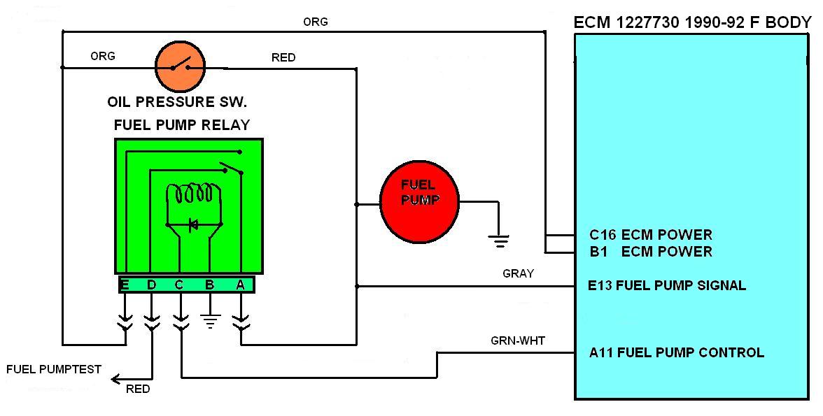
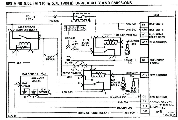
Here's the schematic, of a 1995 corvette fuel pump control. posted below,
save it and print it out.
There are two sources to power the fuel pump.
The PCM enables fuel pump relay #1
As long as the engine is running or cranking.
Otherwise when you turn the ignition on it only enables the relay to provide the fuel pump power for a couple of seconds,
Other source is if the oil pressure switch located next to the rear of the intake ,if the oil pressure is above around 3 psi, 12 volts from fuse ECM Fuse#1
will provide 12 volts to the FP1 fuse#14 which goes to the fuel pump connector Gray wire.
Fuel pump relay #1 is located along the passenger side front edge of the dash. All of the relays
are the same so you can swap them around. Fuel pump relay #2 is used for the LT5 so it
may not be there.
Posted by Hooked on Vettes
Here's the schematic for a 95. I'd think 96 would be the same.
The fuel pump relay is located under the passenger side front edge of the dash. There should be 5 relays.
Relay A for the Horn
Relay B for Fuel Pump #1
Relay C Probably not used. (In 95 used for ZR1 2nd fuel pump)
Relay D for Fog Lamp
Relay E for Courtesy Lamp
Socket F empty not used
The relays on the passenger side wheel well are for the AC Clutch,
and High/Low blower speed relays if you have manual AC (C60).
FUEL LINE SIZE Fuel line size is determined by the horsepower of the engine. Up to 350 HP 5/16" or 4AN Up to 500 HP 3/8" or 6AN Up to 700 HP 1/2" or 8AN Up to 1200 HP 5/8" or 10AN RETURN LINE SIZE Return line size is determined by the output of the fuel pump. Up to *29 gal/hr (110 liters/hr) 1/4" or 3AN Up to *45 gal/hr (170 liters/hr) 5/16" or 4AN Up to *90 gal/hr (340 liters/hr) 3/8" or 6AN Up to *180 gal/hr (680 liters/hr) 1/2" or 8AN *Pump output @ 45psi PUMP SIZE Pump size is determined by the horsepower of the engine. Horsepower x .083 = gallons per hour @ 45 psi Example: 500hp x .083 = 42 gal/hr or Horsepower x .314 = liters per hour @ 45 psi Example: 500hp x .314 = 157 liters/hr NOTE: add 25% to pump size for supercharged applications.
HERES A FAIRLY NEW ,AND VERY INTERESTING ADDITION TO THE POTENTIAL FUEL SYSTEM DESIGN, as IT INCREASES THE FUEL PUMPS ABILITY TO ACCESS FUEL
http://www.motoiq.com/MagazineArticles/ ... rvoir.aspx
ROCK AUTO HAS FUEL PUMPS THAT DON,T COST NEARLY AS MUCH AS MOST AUTO PARTS STORES< BUT KEEP IN MIND BRAND NAME PUMPS TEND TO LAST LONGER THAN BARGAIN BASEMENT PRICE CHINESE IMPORT CRAP
http://www.rockauto.com/catalog/raframe ... nih4detdi1
THERES A BIG DIFFERENCE IN PURCHASING A COMPLETE ASSEMBLY OF MATCHED COMPONENTS FOR $250
vs a BARGAIN BASEMENT PUMP OF UNKNOWN QUALITY FOR UNDER $30
http://www.racetronix.biz/customkititems.asp?kc=FPA-010H
viewtopic.php?f=55&t=10536&p=44732&hilit=holley+fuel#p44732
I bought and have used the BOSCH PUMP, but theres better options available now than there were 12 years ago, ID suggest a 300-350 lph pump with AN#8 lines , and fuel filter on an engine that is intended to produce north of 500hp,
http://garage.grumpysperformance.com/index.php?threads/replacing-a-c-4-fuel-pump.33/
http://members.shaw.ca/corvette86/FuelSystemDiagnosis.pdf
http://www.thecalculatorsite.com/conversions/liquidvolume/liters-to-gallons-(us).php
A common upgrade that frequently works on C4 corvettes but its marginal on a serious race engine in my experience, especially if used with stock fuel lines and filter.
http://www.summitracing.com/parts/vpn-gca758-2/overview/
heres a pump I find works well with AN#8 lines and filters
http://www.summitracing.com/parts/aei-11169
Bosch High Pressure Pump in the tank replacement fuel pump in my 1985 vette when the original pump failed, and yes after helping others install the cheaper knock-offs I think theres a difference in quality,and while the price is higher and there are other options, I would at least consider the better brand name pumps, rather than the less expensive knock-offs.
if you look at places that sell BOTH good quality and bargain priced parts like ROCKAUTO or SUMMIT OR JEGS, youll see theres fuel pumps available from under $30 to over $250 PLUS aftermarket sources can go up from there, theres no way that a fuel pump from a well known manufacturer like lets say BOSCH aeromotiveinc or WELBRO that sells for 8 times what the bargain basement pump is going to be made to the same quality or contain the same attention to detail or have similar component quality, you tend to get what you pay for
http://members.shaw.ca/corvette86/FuelS ... gnosis.pdf
http://www.weldonracing.com/product/64/ ... _Pump.html
first check your shop manual for the fuse and fuse able link locations
fuses are located in several locations and fuse-able links near the battery
Bosch High Pressure Pump 0-580-254-984
Rated at 44 GPH @ 90 PSI 750+ Hp This pump is identical to the Accel part number 74702 which they boast will handle 870 Hp!
http://www.lucasinjection.com/bosch_and ... _pumps.htm
http://www.expressfuelpumps.com/
http://www.boschfuelpumps.com/
http://www.caspeed.com/boschpump/boschpump.html
the fuel pump has a 12 volt 15 AMP fused circuit
Under the hood--to the right of the blower motor---should be 2 relays---fuel pump is the one farthest to the right.
theres a good deal of good and useful advise, in this thread but Id point out the
sensor(s) next to the distributor, base ,could be a cause of a problem, because occasionally one of these starts acting up intermittently causing the fuel pump or ECM to stop working,or the VATS system, or the FUEL SUPPLY SYSTEM.
READ THRU THIS LINKED INFO
http://www.joby.se/corvette/mods/2001-0X07_fuelpump/
heres some other possibility,s
http://members.shaw.ca/corvette86/FuelS ... gnosis.pdf
http://www.eurovettes.com/c4_faultcodes.htm
http://chevythunder.com/fuel injection ecm pinouts.htm
http://garage.grumpysperformance.com/index.php?threads/installing-a-fuel-cell.733/#post-3532
read thru these threads also, as theres a good deal more related info in those threads and links
obviously the first step is PROVING its the FUEL PUMP ITSELF THAT NEEDS REPLACEMENT AND NOT A FUSE OR RELAY OR SENSOR SO READ THRU THESE SUB LINKS, and DO A FEW TESTS BEFORE JUST ASSUMING ITS A DEFECTIVE FUEL PUMP,
If the ECM sees oil pressure greater than 4 PSI and the reference pulses from the distributor, it will energize the injector drivers
The ECM will also pull in the fuel pump relay in effect paralleling it electrically with the oil pressure switch.
(If the fuel pump relay fails, you can still normally get the car to start and run unless you can,t make at least 4 PSI oil pressure. This is a limp home mode feature put in place to allow for a fuel pump relay failure).
viewtopic.php?f=32&t=596
http://www.corvette-guru.com/modules/ne ... post129791
its not necessary to drain the tank but its a good idea to do so.
IT IS NECESSARY TO DISCONNECT THE BATTERY READ THAT AS ABSOLUTELY MANDATORY during the swap procedure to prevent any chance of accidental problems
step one have the parts on hand PLUS 3 ft of 3/8" fuel line and 1 ft of 5/16" fuel line , I know, you may not need the fuel line but in many cases its faster and easier to remove the old line and replace with new ones
hose clamps, youll want several 1/2" size for the lines
fuel pump
http://www.ecklers.com/product.asp?pf_id=30666&dept_id=1277
fuel pump screen
http://www.ecklers.com/product.asp?pf_id=30668&dept_id=1277
fuel filter
http://www.ecklers.com/product.asp?pf_id=A3479&dept_id=1303
(optional but a GREAT IDEA)
ok, step one,
make darn sure the keys are out of the car and the battery is disconnected for extra safety
step two, open the fuel fill door center rear deck where you normally fill the car and remove the gas cap
step three
remove the four very small torx screws in the corners and lift off the door assembly
step four
theres a rubber bib fuel spill tray)(around the fill spout, remove the gas cap and work the bib fuel spill tray ) (out , and disconnect the water drain line and label it with masking tape/pen
step five
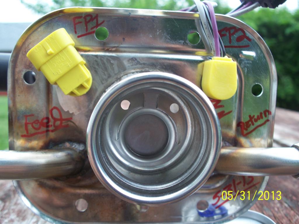
label the three lines with masking tape/pen (upper line/lower line /left side line)
remove each at the central point in the opening, then disconnect the electrical connector on the lower edge of the opening
step six
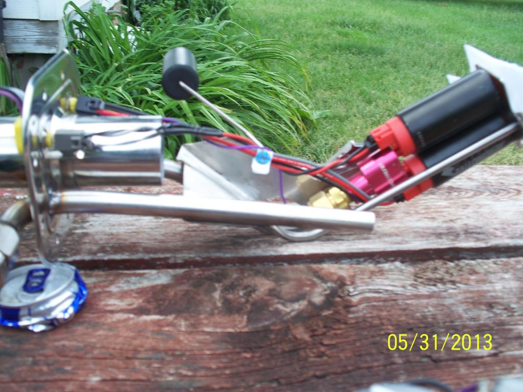
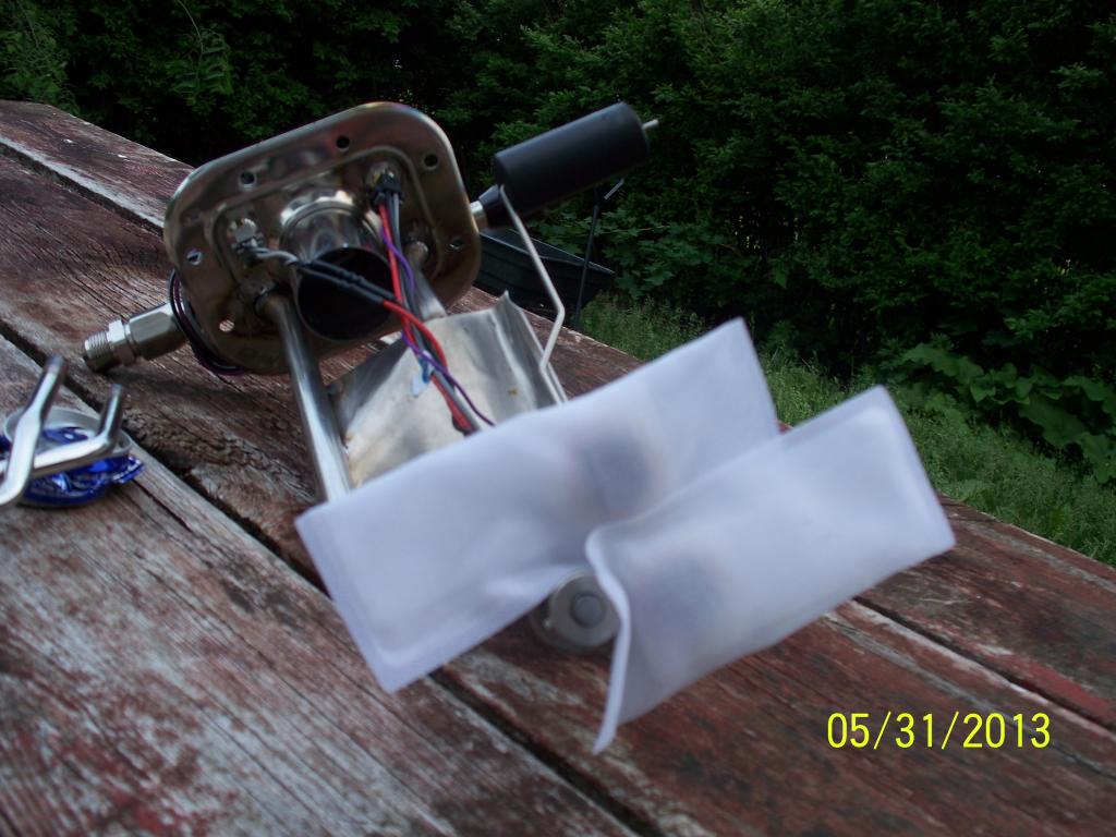
remove the 8 10mm bolts and look carefully at where the components go, after they are removed the pump lifts up and out, the pump normally comes with instructions also, but its fairly simple, the pump, lines and fuel level sensor lifts out as a sub assembly, look thru the link below for pictures and more info
the stock pump puts out less than 60 gallons an hour
http://aeromotiveinc.com/tech-help/freq ... uel-pumps/
340 liters per hour flow should be good for/ approximately 700HP (thats approximately 90 gallons an hour
just a bit of related info that may or may not apply in your case, electric in tank fuel pumps are COOLED by both sloshing fuel and fuel flow rates and are DESIGNED to be used with a return style fuel pressure regulator, use with a nearly empty fuel tank or with a dead head style fuel pressure regulator will DRASTICALLY reduce the pumps life expectancy
http://www.racerpartswholesale.com/prod ... And_Wiring
heres a 200 gallon an hour rated pump that should easily supply over 1000hp, but youll need AN#8 or larger fuel lines
http://aeromotiveinc.com/wp-content/upl ... _guide.pdf
BTW RELATED THREADS
the fuel pump has a 12 volt 15 AMP fused circuit
http://store.summitracing.com/parts/aei-11169
http://forum.grumpysperformance.com/viewtopic.php?f=55&t=635
http://forum.grumpysperformance.com/viewtopic.php?f=55&t=211
http://forum.grumpysperformance.com/viewtopic.php?f=55&t=1200
http://forum.grumpysperformance.com/viewtopic.php?f=55&t=3165&p=8442#p8442
"I have replaced countless in tank fuel pumps. In tank fuel pumps are submerged in fuel in order to help them run cooler. I see many people out there (especially with today's gas prices) who run their vehicles on the empty side of the tank. Empty tank=hot pump. It's just as easy to keep the top half filled as the bottom half. Keeping adequate gas in the tank in conjunction with a regular filter change will insure your pump will last it's longest."
http://www.joby.se/corvette/mods/2001-0X07_fuelpump/
NOW IF YOU WANT TOO UPGRADE HERES A MORE USEFUL LINK WITH PART NUMBERS
http://www.caspeed.com/boschpump/boschpump.html
http://www.racetronix.biz/customkititem ... A-010H&eq=
255 liters per hour flow should be good for/ approximately 500HP
access to the fuel pump is thru the panel around the tank fill cap SIMILAR TO THIS, held in place with 10mm bolts in this picture
label the fuel return lines before you disconnect them to insure replacing them correctly
https://www.ecklerscorvette.com/corvette-gas-tank-filler-neck-seal-1984-1996.html
Fuel Pump
http://boschfuelpumps.com/
In a C4 Corvette, the fuel pump is one of those crossover items that is part of both the electrical system and the fuel system. The pump is a submerged variety, electrically operated, contained in the fuel tank and somewhat difficult to get to.
Although the pump is difficult to physically check, you can make certain that it at least runs by turning the ignition switch to on (but don't start the engine).
If the pump motor is working, you will hear a whirring noise coming from from the rear of the vehicle that will last for 2 seconds. Note that this does not prove that the pump is actually pumping fuel in sufficient quantity and/or pressure but it does prove if the pump motor itself is operating.
If you do not hear any sound, check the fuse labeled "Crank" on the fuse panel.
If the fuse is not blown but there is no sound from the tank area, there is a problem with either the motor or the wiring feeding the fuel pump motor.
If the pump appears to be working, you will need to measure the fuel pressure at the Shraeder valve located on the fuel rail on the engine. Anything below 35 PSI is cause for alarm and can be the fuel pump (pumps---2 each---on a ZR-1), the fuel pressure regulator, the check valves in the fuel return line, the fuel filter or a obstructed fuel line.
Once you have troubleshooted your Corvette’s Fuel System and determined it is time to install a new fuel pump & sending unit on your Corvette you will first need to disconnect the negative battery cable and relieve the pressure in the fuel system. To relieve the fuel system pressure on a C4 Corvette you can simply remove the gas cap and let the car sit for 15 minutes. Once the pressure is relieved drain your Corvette’s fuel tank and remove the tank filler door attaching screws and bezel. Next, lift the fuel tank filler pipe housing and disconnect the drain hose from the nipple. Before disconnecting the fuel tank filler pipe housing, clean all fuel connections and surrounding areas to avoid contaminating the fuel system. Next disconnect the fuel hoses and EVAP hose from the fuel sender assembly. Plug or pinch the fuel feed and return hoses and remove the fuel sender electrical connector. To finish removal of your C4 Corvette’s fuel pump and sending unit remove the fuel sender assembly attaching screws, assembly, and gasket. You can re-install the old gasket but first check to see if your new C4 Corvette Sending Unit came with a new gasket. If it did then discard the gasket and thoroughly clean the gasket sealing surfaces. If you just purchased a new C4 Corvette Fuel Pump you will need to purchase a gasket separately or re-install the old gasket. Finally, cuts, nicks, swelling, or distortion is common on the fuel feed, fuel return and EVAP hoses so be sure to inspect these hoses before proceeding.
Once you are ready to install your new C4 Corvette Fuel Pump & Sending Unit begin by positioning the gasket on the fuel tank with the notch facing forward in the right hand corner of the tank. Carefully fold the strainer to allow it to fit through the opening in the tank. Next, install the fuel sender assembly into the fuel tank and re-connect the fuel sender electrical connector. Then connect the EVAP hose and tighten the hose clamps. Re-connect the fuel drain hose to the nipple on the filler pipe housing and place the housing around the filler pipe. Now you can re-install the filler door bezel, add fuel, and re-connect the negative battery cable. Before driving your Corvette away, be sure to turn the ignition switch on, off, then back on and check for any possible fuel leaks. If no leaks are recognized your Corvette fuel pump replacement was a success.
the answer to how big a fuel pump yoou need or what injector size is required or what fuel pressure level will be necessary is a predicable value and it depends on what power range your dealing with and what your trying to supply with fuel and the rate its potentially using that fuel, the stock fuel pump will easily supply 400hp plus on a c4 corvette or a bit more and the stock injector size won,t
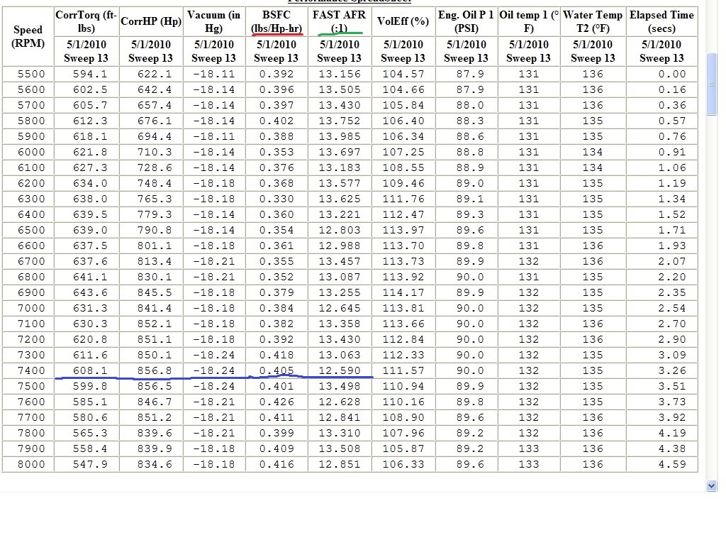
it takes (X) amount of fuel/air mix at about a 13:1-14:1 ratio being burned per minute to make (Y) amount of HORSEPOWER
you can spin a small engine fast or a big engine slower but it will take a certain amount of fuel being consumed to produce a power level and its reasonably predictable at about a BSFC of about .5-.55, you might be amazed at what you can learn reading thru the linked info on the site.
the fuel filters located under the front pass side door area near the frame and the shop manual will go into some detail on its removal, yes your going to loose some fuel so its best to do this up on a lift or jack stands where access is easier and where you can see what your doing.
theres an arrow on the filter indicating direction of fuel flow for a reason , pay attention and do it correctly, have some shop towels and a fire extinguisher handy ANYTIME you work on fuel lines!
Fuel System
The TPI Fuel System comprises the following components:
- Fuel Tank
- Fuel Pump
- Fuel Pressure Regulator
- Fuel Lines
In the original GM applications, the fuel injection pressure pump is installed inside the vehicles fuel tank. Adapting this pump has never seemed to us a practical solution, unless you are installing the TPI system on a vehicle that utilises the stock GM gasoline tank. This would allow for the installation of an internal tank type pump. If you are installing the TPI system into a vehicle that was originally equipped with carburettors, or even a throttle body fuel injection system, it WILL be necessary to install a compatible high pressure port fuel-injection type pump. Any number of fuel pumps will serve the purpose. We can recommend the fuel pump from a 78-80 and 82-85 Datsun 280Z. The Nissan part number for this pump is 17011-P7211. In addition, these pumps are usually readily available from wrecking yards, as are similar units from BMW, Mercedes Benz, Jaguar and many other late-model port-injected vehicles.
The electric fuel pump used should be capable of maintaining at least 50 psi under full throttle, and a return line MUST be plumbed back to the fuel tank/tanks if there is not one installed on the car!
IF THE FUEL TANK IN YOUR VEHICLE DOES NOT HAVE PROVISION FOR A RETURN LINE, IT IS NOT NECESSARY TO MODIFY THE TANK!
By installing the appropriate size tee-fitting into the fuel supply line from the tank to the inlet side of the fuel pump and connecting the return line into this suction line at the newly installed tee, the need for a return line can be met without removing and modifying the fuel tank.
If you are installing your TPI system in a vehicle which was originally equipped with a carburetted engine and a mechanical fuel pump that was equipped with a factory installed return line, BE AWARE, that many of these systems have a restriction in the return line. This restriction should be removed to eliminate the possibility of unnecessarily high pressures in this portion of the fuel system. These restrictions are often contained in the return line fitting on the gas tank sending unit mounting flange. If it is inconvenient to access this flange to remove the restriction, the return line can be re-routed to the fuel pump inlet line, as described above.
Fuel Regulator
A fuel pressure regulator is mounted on the rear of the right side of the TPI fuel rail. This non-adjustable regulator controls fuel pressure, to maintain it at about 41 psi under high vacuum conditions, such as idle, and up to 47 psi under low vacuum conditions, such as full throttle operation. Adjustable fuel pressure regulators are available through a number of after-market suppliers, for high performance applications.
Fuel Lines
Because of the high fuel pressures involved, we prefer to use braided stainless fuel lines with threaded connectors, as opposed to just using hose clamps and rubber hose, when making the connection between the TPI unit and the fuel pump! The pressure inlet of the TPI system is the fitting with the larger I.D. A return line MUST be connected from the petrol tank to the smaller I.D. fitting. If you are utilising braided stainless hose and fittings, it will be necessary to purchase after-market adaptor fittings which thread into the hose connections, or the TPI manifold, to allow the use of these improved hose and fitting assemblies, since the OEM connections utilise metric threads and O-ring type seals. These adaptor fittings are available, either in a male configuration for installation into the fittings on the fuel rails of the TPI or, into the ends of the stock rubber hoses which attach to the body/frame mounted steel fuel lines that come forward from the fuel tank, or in a female configuration, for installation onto the end of the engine mounted steel tubing extensions, which are a part of all factory TPI fuel line installations.
The above-mentioned items are all that could be considered separate elements of which are component parts of the TPI installation. Simply stated, the system will not work at its designed level of performance if any one of the above items is deleted! The following information will include some additional items which, while not required to make the system functional, are items that are utilised in the factory installation to make everything work as originally designed, and which may be used, as necessary, or deleted if so desired, with no functional effect on the real world operation of the unit.
http://garage.grumpysperformance.co...uick-disconnect-fuel-line-related-info.16693/
http://forum.grumpysperformance.com/viewtopic.php?f=55&t=635
http://forum.grumpysperformance.com/viewtopic.php?f=55&t=211
http://chevythunder.com/fuel injection troubleshooting page C.htm
http://forum.grumpysperformance.com/viewtopic.php?f=55&t=1200
http://forum.grumpysperformance.com/viewtopic.php?f=55&t=3165&p=8442#p8442
Last edited by a moderator: