READ thru these links as theres alot of good info
Here is an excerpt from an AERA TB,,
===================
Exhaust Valve Guide Caution On
1965-98 GM Big Block Engines
These engines' valve guides were not intended as a replacement item from GM.
The guides were located into the head castings after the head was cast and
the exhaust guide is "water cooled".
The water-cooled guide also has two different size press fit diameters. Adding additional confusion to the matter, they also switched the location of the larger diameter sometime in 1985.
To determine which outside diameter guide you have and which direction to
remove an exhaust valve guide, the following procedure is suggested:
Drive the guide no more than .250" (6.35 mm) toward the valve spring side of
the head and stop. Then, measure the newly exposed area of the guide
OD next to the spring pad.
If the measurement is .620" it is the first style guide. To remove this
style guide, continue driving it toward the valve spring side of the head.
If the measurement is .616" , it is the second style guide. To remove
this style guide, you must drive it the opposite direction toward the combustion
chamber side of the head.
valve seal wear, and you can use a great deal of oil if they are in need of replacement, youll also want to verify the condition of your valves and valve guides
Many teflon valve guide seal designs are not very flexible and if the valve guides are a bit loose they can leak considerable oil,Switching to the more flexible viton seals can at times help reduce oil consumption issues
http://www.summitracing.com/search/Part ... oelastomer
WATCH THE VIDEO
http://howautowork.com/part_1/ch_1/valve_spring_22.html
http://www.summitracing.com/search/Part ... oelastomer
http://www.cranecams.com/pdf/10g.pdf
http://blogs.solidworks.com/roadster/20 ... _valv.html
viewtopic.php?f=52&t=1053&p=1989#p1989
http://www.vettenet.org/vlvseals.html
viewtopic.php?f=52&t=61
http://www.iskycams.com/onlinecatalog.html
http://www.aa1car.com/library/ar696.htm
http://www.ehow.com/how_2110646_replace ... ngine.html
http://www.darklair.com/monte/howto/how ... seals.html
http://www.ehow.com/how_2110646_replace ... ngine.html
http://store.summitracing.com/egnsearch ... 5&x=38&y=8
http://store.summitracing.com/egnsearch ... &x=30&y=13

your going to need to read thru these threads below also
viewtopic.php?f=52&t=1005
viewtopic.php?f=52&t=181
viewtopic.php?f=52&t=61
viewtopic.php?f=52&t=984&p=1723&hilit=guides#p1723
theres a good deal of useful info in this article
http://www.customclassictrucks.com/tech ... index.html
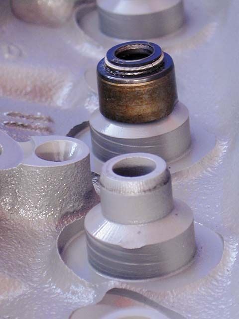
The valveguides for the Vortec heads are the same as all other small-block cylinder heads, but the Vortec heads come equipped with large valveguide seals.
The valveguide seals keep oil from running down both the valve stem and valveguide, and entering the combustion chamber through the intake port at high-engine vacuum and the exhaust port when the engine is not running. This cuts down on engine smoke and exhaust emissions.
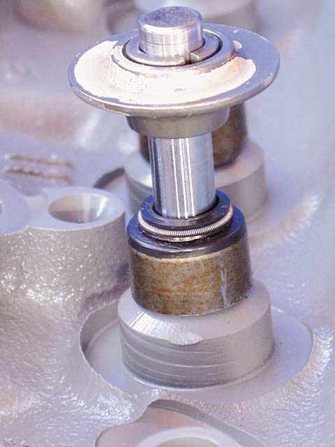
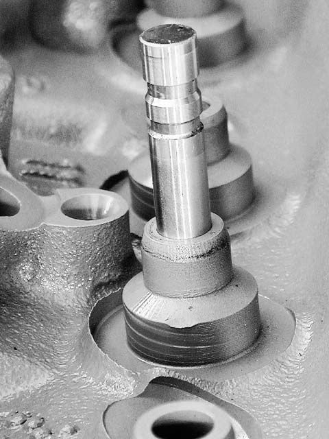
This is the valvespring retainer installed without the valvespring. The maximum amount of valve lift that the Vortec head will tolerate is the distance between the bottom of the retainer and the top of the valveguide seal.
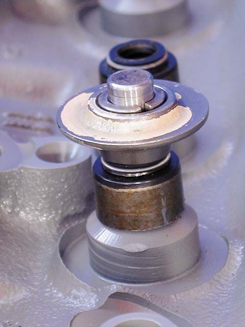

The maximum amount of valve lift before the spring retainer hits the valve guide seal is 0.530 inches. It is generally accepted that 0.060 inches clearance needs to be maintained between the retainer and seal (0.530 - 0.060 = 0.470 maximum valve lift). The Vortec heads, as they come with the large valve guide seals, are only capable of accepting a camshaft with a maximum valve lift of 0.470 inches.
All small-block cylinder heads built before the '96 Vortec heads had two grooves on the valve stems.
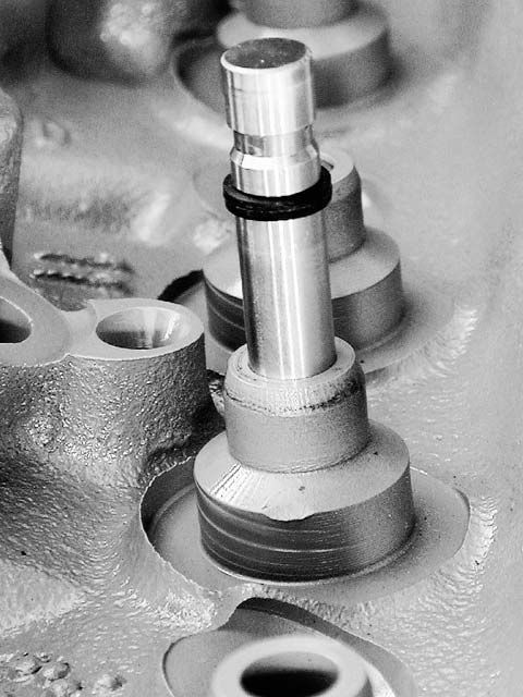
The second groove accepts a quad ring. It sits just below the split lock retainers. The O-ring keeps the oil, which lubricates the rocker arm/valve stem tip, from running down the valve stem and into the valve guide.
Small Block Vortec Cylinder Heads Specifications - Heads Up!
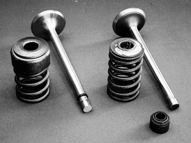
The O-ring must be accompanied by a tin shield over the outside of the valve spring (left). The tin shield keeps excess oil from splashing on the valve stem and valve guide. The tin shield and O-ring must be used together to be effective. Installing the earlier double-groove valves, an O-ring, and a tin shield will allow the Vortec heads to use camshafts with 0.500 inches of valve lift, without machining the valve guides lower for clearance.
a good example for the oil sludge build-up on the back of an intake valve that results from bad valve seals and loose valve guide clearances
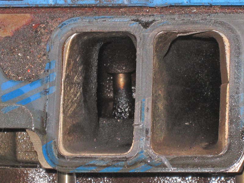
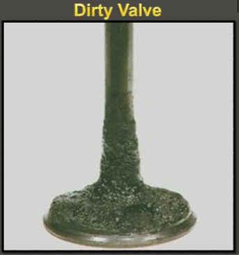
bad valve seals and worn valve guides contribute to most of that build up, not changing oil and over heating and bad valve train geometry tends to add or speed the wear on seals and guides
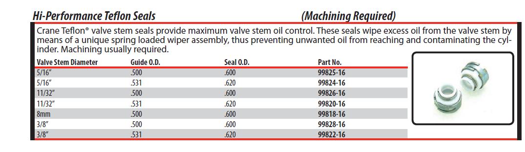
CRANE CAMS SELLS TEFLON VALVE SEALS,they are commonly packaged on blister packs
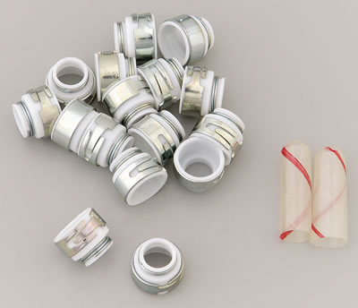
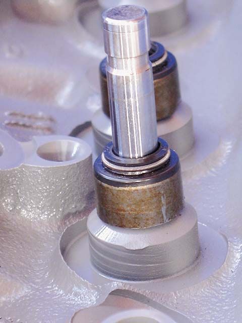
the two striped things are plastic valve seal alignment guides that are temporarily placed over the top of the valve stem, then oiled lightly, they are placed over the valve keeper lock grooves to prevent the seals being damaged during the valve seal installation process.
Here is an excerpt from an AERA TB,,
===================
Exhaust Valve Guide Caution On
1965-98 GM Big Block Engines
These engines' valve guides were not intended as a replacement item from GM.
The guides were located into the head castings after the head was cast and
the exhaust guide is "water cooled".
The water-cooled guide also has two different size press fit diameters. Adding additional confusion to the matter, they also switched the location of the larger diameter sometime in 1985.
To determine which outside diameter guide you have and which direction to
remove an exhaust valve guide, the following procedure is suggested:
Drive the guide no more than .250" (6.35 mm) toward the valve spring side of
the head and stop. Then, measure the newly exposed area of the guide
OD next to the spring pad.
If the measurement is .620" it is the first style guide. To remove this
style guide, continue driving it toward the valve spring side of the head.
If the measurement is .616" , it is the second style guide. To remove
this style guide, you must drive it the opposite direction toward the combustion
chamber side of the head.
valve seal wear, and you can use a great deal of oil if they are in need of replacement, youll also want to verify the condition of your valves and valve guides
Many teflon valve guide seal designs are not very flexible and if the valve guides are a bit loose they can leak considerable oil,Switching to the more flexible viton seals can at times help reduce oil consumption issues
http://www.summitracing.com/search/Part ... oelastomer
WATCH THE VIDEO
http://howautowork.com/part_1/ch_1/valve_spring_22.html
http://www.summitracing.com/search/Part ... oelastomer
http://www.cranecams.com/pdf/10g.pdf
http://blogs.solidworks.com/roadster/20 ... _valv.html
viewtopic.php?f=52&t=1053&p=1989#p1989
http://www.vettenet.org/vlvseals.html
viewtopic.php?f=52&t=61
http://www.iskycams.com/onlinecatalog.html
http://www.aa1car.com/library/ar696.htm
http://www.ehow.com/how_2110646_replace ... ngine.html
http://www.darklair.com/monte/howto/how ... seals.html
http://www.ehow.com/how_2110646_replace ... ngine.html
http://store.summitracing.com/egnsearch ... 5&x=38&y=8
http://store.summitracing.com/egnsearch ... &x=30&y=13
your going to need to read thru these threads below also
viewtopic.php?f=52&t=1005
viewtopic.php?f=52&t=181
viewtopic.php?f=52&t=61
viewtopic.php?f=52&t=984&p=1723&hilit=guides#p1723
theres a good deal of useful info in this article
http://www.customclassictrucks.com/tech ... index.html
The valveguides for the Vortec heads are the same as all other small-block cylinder heads, but the Vortec heads come equipped with large valveguide seals.
The valveguide seals keep oil from running down both the valve stem and valveguide, and entering the combustion chamber through the intake port at high-engine vacuum and the exhaust port when the engine is not running. This cuts down on engine smoke and exhaust emissions.
This is the valvespring retainer installed without the valvespring. The maximum amount of valve lift that the Vortec head will tolerate is the distance between the bottom of the retainer and the top of the valveguide seal.
The maximum amount of valve lift before the spring retainer hits the valve guide seal is 0.530 inches. It is generally accepted that 0.060 inches clearance needs to be maintained between the retainer and seal (0.530 - 0.060 = 0.470 maximum valve lift). The Vortec heads, as they come with the large valve guide seals, are only capable of accepting a camshaft with a maximum valve lift of 0.470 inches.
All small-block cylinder heads built before the '96 Vortec heads had two grooves on the valve stems.
The second groove accepts a quad ring. It sits just below the split lock retainers. The O-ring keeps the oil, which lubricates the rocker arm/valve stem tip, from running down the valve stem and into the valve guide.
Small Block Vortec Cylinder Heads Specifications - Heads Up!
The O-ring must be accompanied by a tin shield over the outside of the valve spring (left). The tin shield keeps excess oil from splashing on the valve stem and valve guide. The tin shield and O-ring must be used together to be effective. Installing the earlier double-groove valves, an O-ring, and a tin shield will allow the Vortec heads to use camshafts with 0.500 inches of valve lift, without machining the valve guides lower for clearance.
a good example for the oil sludge build-up on the back of an intake valve that results from bad valve seals and loose valve guide clearances
bad valve seals and worn valve guides contribute to most of that build up, not changing oil and over heating and bad valve train geometry tends to add or speed the wear on seals and guides
CRANE CAMS SELLS TEFLON VALVE SEALS,they are commonly packaged on blister packs
the two striped things are plastic valve seal alignment guides that are temporarily placed over the top of the valve stem, then oiled lightly, they are placed over the valve keeper lock grooves to prevent the seals being damaged during the valve seal installation process.