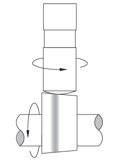
How do you determine the spring pressure needed to keep the valves under control for a given lift, duration, and max rpm.
It might take you several hours to read thru all the links and sub links but its time very well spent as it could save your engine from destruction and save you thousands of dollars
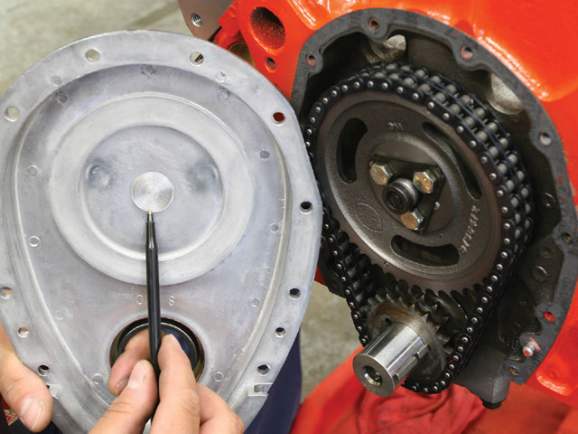
ALWAYS ask detailed questions as to the best , and most durable parts combination they have available , for your application, from your cam suppliers tech department.
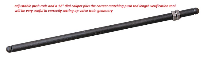
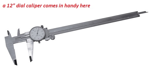
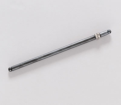
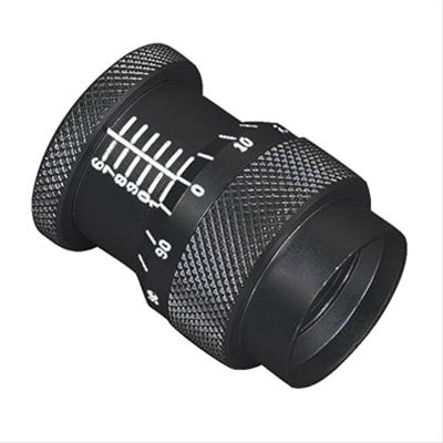
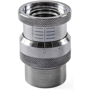
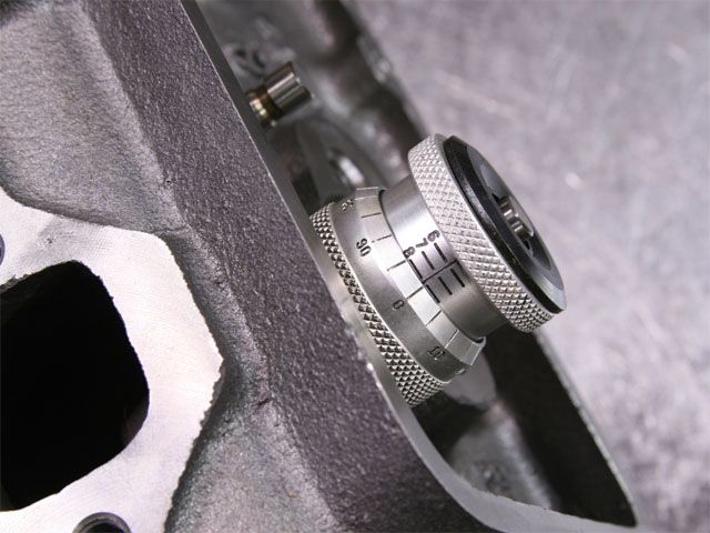
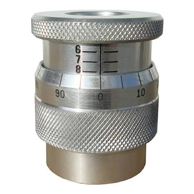
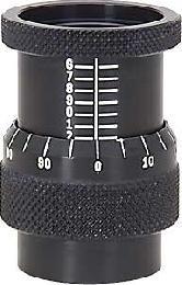
youll want some tools, naturally the amount of info you need and how precisely youll want to control your valve train will effect the tools and info required and to some extent the higher the rpm levels the higher the cost of tools and components required will be, for a basic street small block a black magic marker and a feeler gauge, and adjustable length push-rod and a geometry check tool can give you the basic info required
these tools come in different designs but youll want ones matching your application, in many cases the cam manufacturers and cylinder head manufacturers can give you a great deal of good info on common applications ,clearances and spring load rates and valve train geometry required, IF YOU fail to get the valve train clearances, piston to valve or rocker geometry correct and youll very quickly break parts.
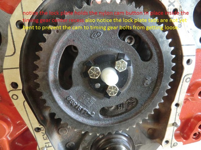
If your ordering any cam, be very sure you explain what year block and what cylinder heads will be used as there are differences in the cams. between early and later SBC, block s and the cams they require,and on big blocks theres similar issues, a mark VI cam is different from a MARK IV cam
Recommended Valve Spring Pressures
ID STRONGLY SUGGEST THIS READING ASSIGNMENT
preventing cam & lifter break-in failures
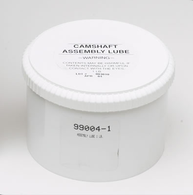
it should be rather obvious that there's options,you'll chose in both valve train components and lubricants, cam failures are usually the result of incorrect CLEARANCES or too much SPRING PRESSURE or LACK of ADEQUATE LUBRICATION,USE DECENT MOLY CAM LUBE, and decent quality oil, adding MAGNETS to trap metallic CRUD HELPS, if your not getting constant oil flow from each rocker /push rod at idle theres something wrong and that needs to be checked
https://www.youtube.com/watch?v=o5is9BsH5OU
yes I know you want to skip reading links and sub links... its to your benefit to take the time and effort, to read through them
http://garage.grumpysperformance.co...ch-quest-series-similar-350-383-sbc-info.519/
http://garage.grumpysperformance.com/index.php?threads/tbucket-engine-project-dart-shp.3814/
http://garage.grumpysperformance.com/index.php?threads/sellecting-cylinder-heads.796/
http://garage.grumpysperformance.com/index.php?threads/what-to-look-for-in-a-good-engine-combo.9930/
http://garage.grumpysperformance.com/index.php?threads/my-1st-street-383-build.6962/
http://garage.grumpysperformance.co...383-build-that-is-now-going-to-be-a-400.7804/
http://cranecams.com/userfiles/file/334-343.pdf
http://www.woodcarbs.com/valvesprings.htm
http://www.jesel.com/valvetrain/index.p ... rs/tie-bar
https://www.enginebuildermag.com/2010/01/street-performance-cylinder-heads/
https://www.hotrod.com/articles/ccrp-1209-eight-budget-sbc-head-shootout/
http://www.superchevy.com/how-to/engines-drivetrain/sucp-0705-budget-chevy-cylinder-heads/
http://www.superchevy.com/how-to/engines-drivetrain/sucp-0803-performance-cylinder-head-comparison/
http://garage.grumpysperformance.com/index.php?threads/ccing-my-heads.14187/#post-71989
http://garage.grumpysperformance.co...ich-is-best-steel-or-aluminum.3124/#post-9141
http://garage.grumpysperformance.com/index.php?threads/rhodes-lifters.1552/#post-6067
https://sdparts.com/details/scoggin-dic ... ter/sd1005
viewtopic.php?f=52&t=9687&p=48105#p48105
http://www.usaperform.com/documents/Spe ... 0Chart.pdf
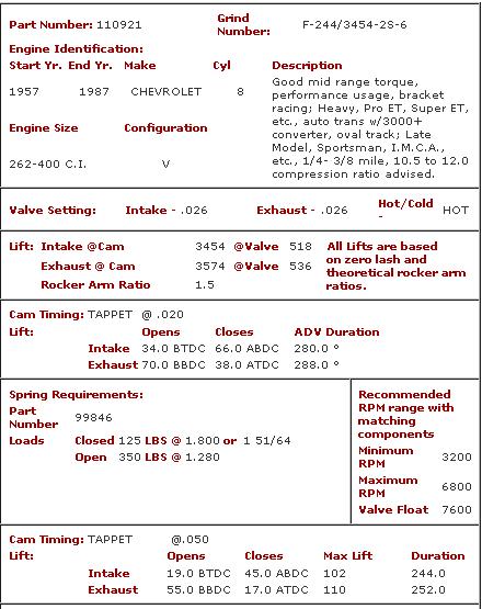
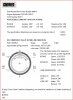
Please note, the valve spring pressure figures given here are guidelines only. Some special applications may require different pressures. When in doubt, please contact your camshaft supplier.
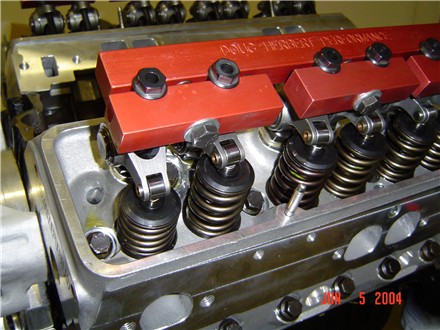
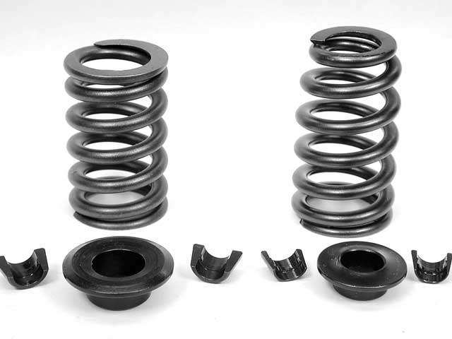
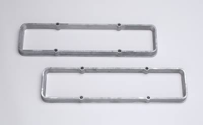
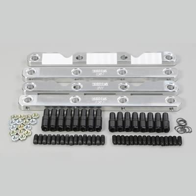
ID prefer to use the hardened steel, cup style, valve spring seats, rather than the inner spring diam. style spring seats, if I have the room with the proper machine work of course.
but those are mostly used with single springs , the inner spring diam. seats
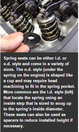
are frequently used with dual valve springs and a damper, so you will be using the matched components depending on existing clearances
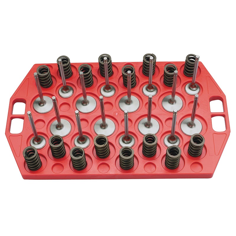
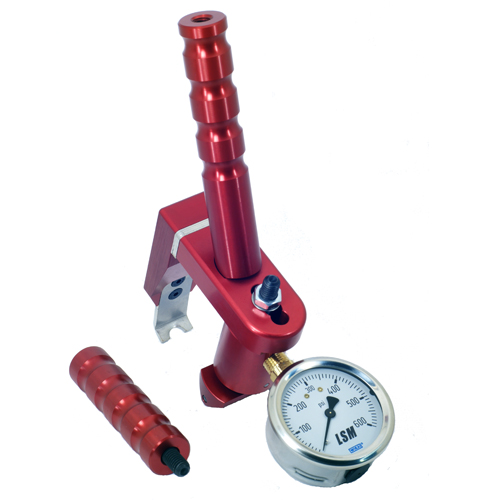
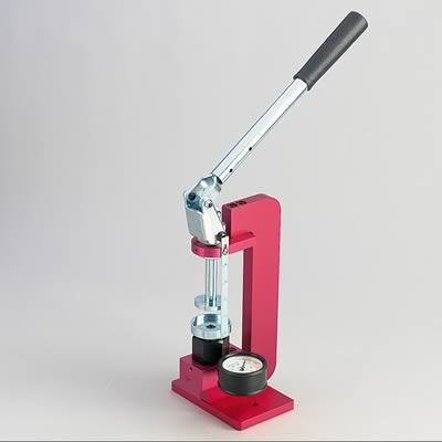
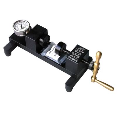
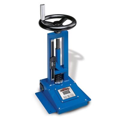
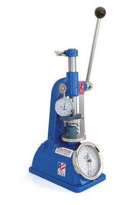
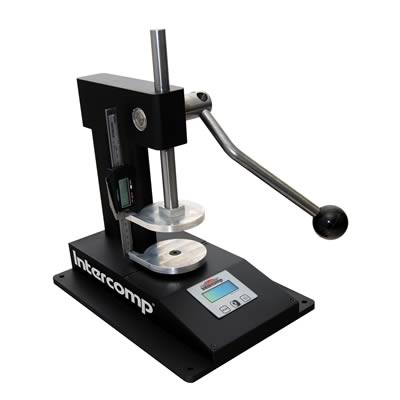
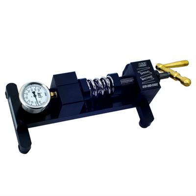
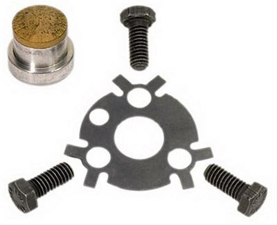
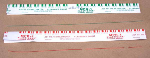
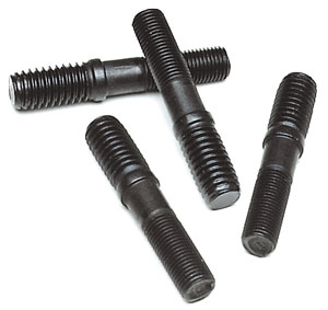
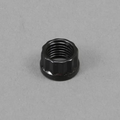
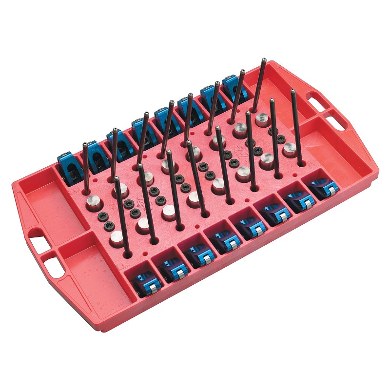
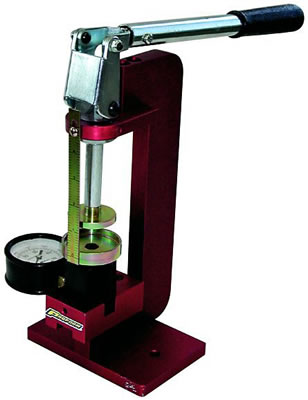
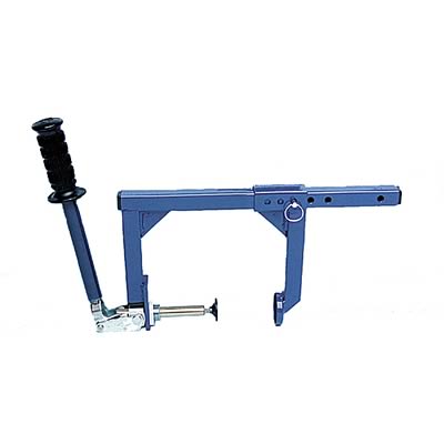
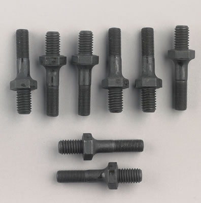
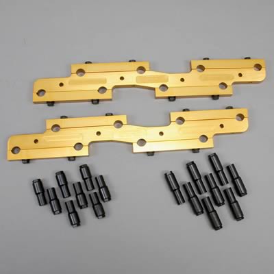
youll need these also
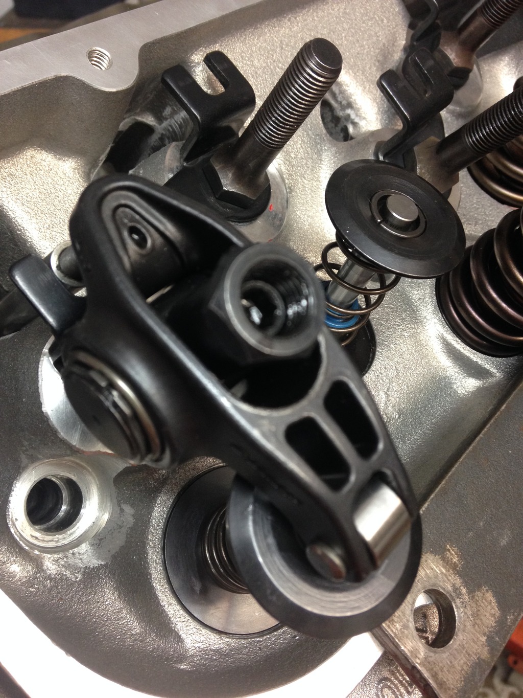
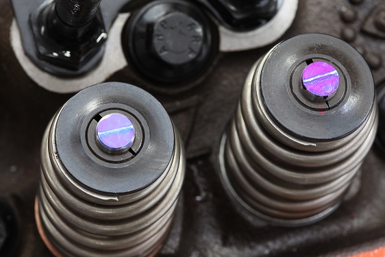
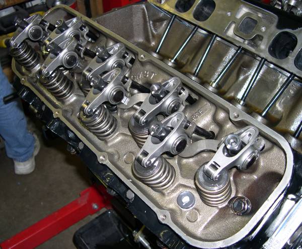
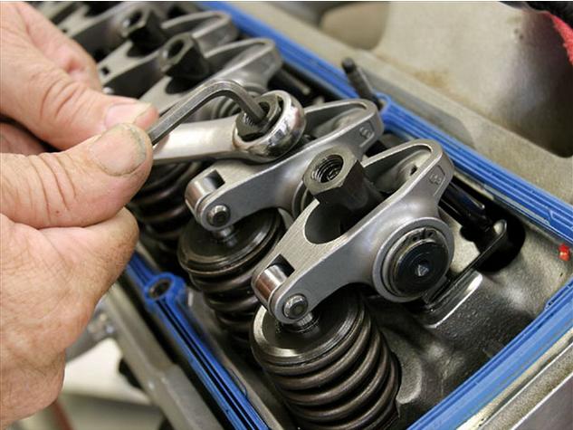
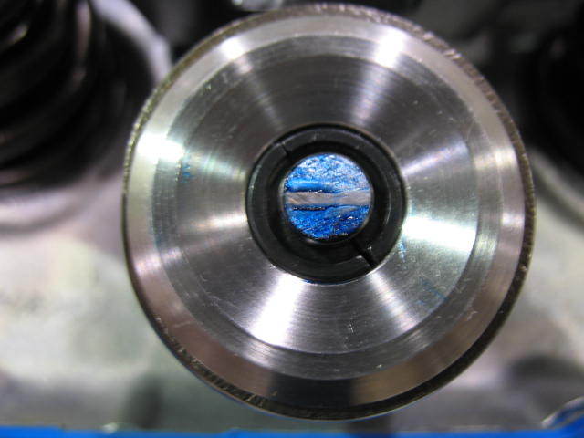
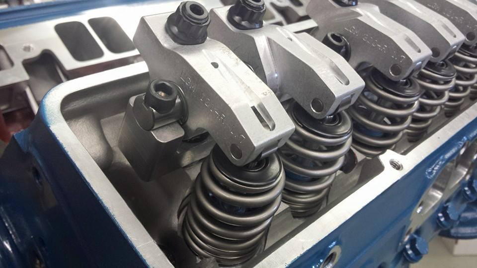
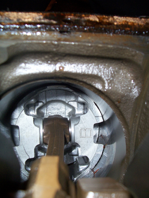
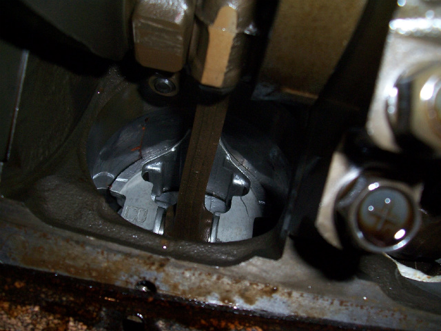
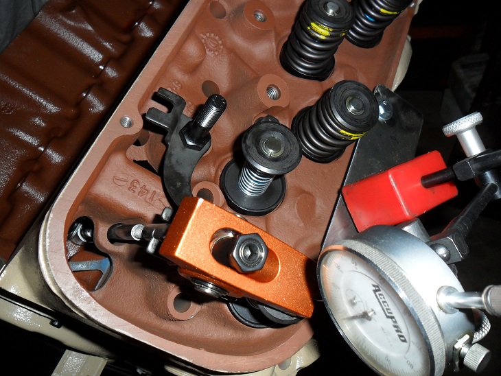
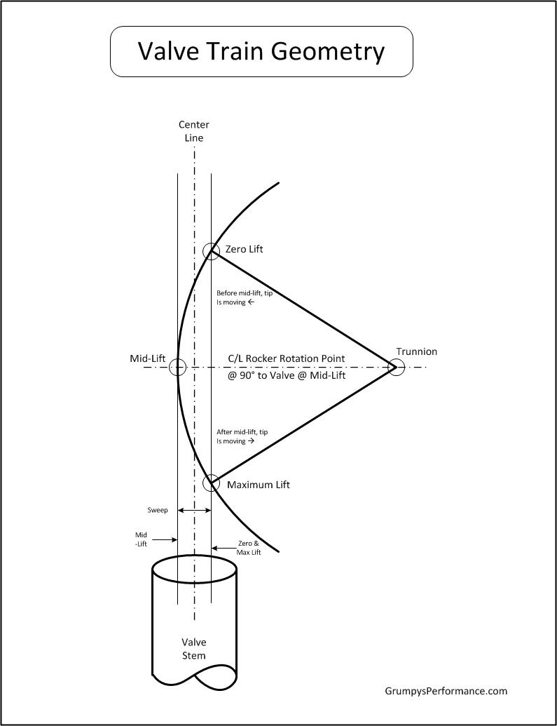
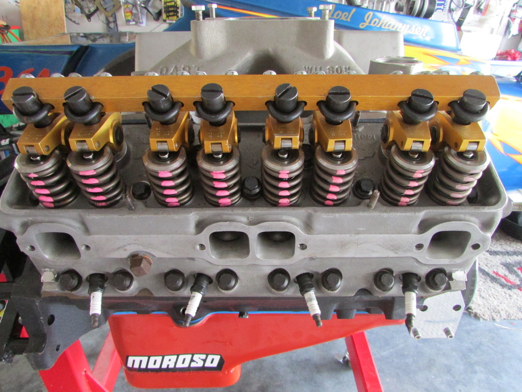
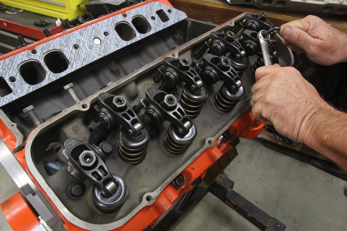
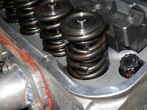
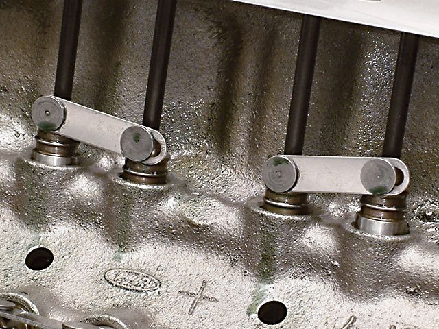
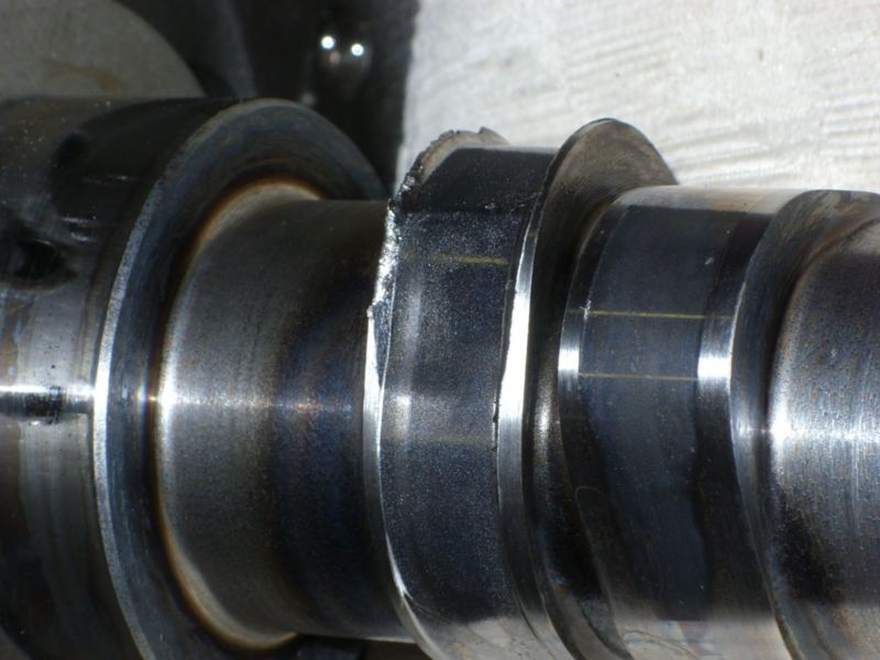
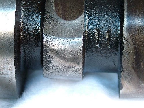
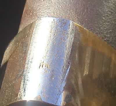
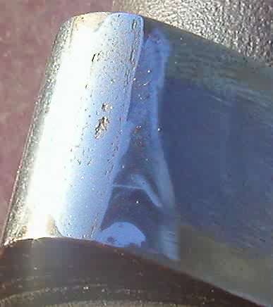
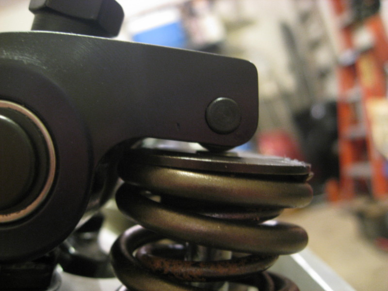
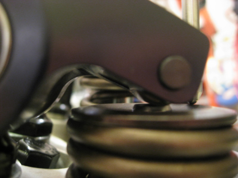
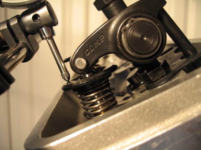
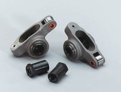
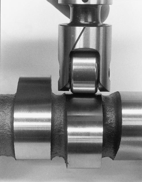
in an ideal valve train geometry set-up the sweep mark on the valve tip will be very narrow and close to the valve center-line , but having the sweep mark narrow is more important than keeping it centered on the valve stem tip, the valve train does not like lateral or side ways loads on the valves and the wider sweep is an indicator of that issue, while a correctly set up valve train may have components that result in the valve tip sweep mark being slightly off the valve center-line this is not a major concern.
Its checking and verifying the valve train clearances and basic geometry that should be your major concern
check all valve train geometry and clearance on any engine you assemble or modify the valve train on.
the clearances and rocker geometry (push rod length,spring bind rocker to rocker stud clearance, etc.) must be checked carefully prior to starting the engine
http://www.summitracing.com/search/...d-length-checkers?autoview=SKU&ibanner=SREPD5
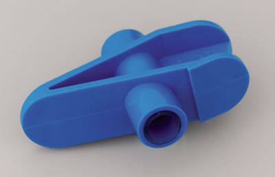
Proform Pushrod Length Checkers 66789 SBC 3/8" rocker studs
Proform Pushrod Length Checkers 66790 SBC 7/16" rocker studs
Proform Pushrod Length Checkers 66806 BBC 7/16" rocker studs
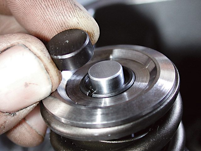
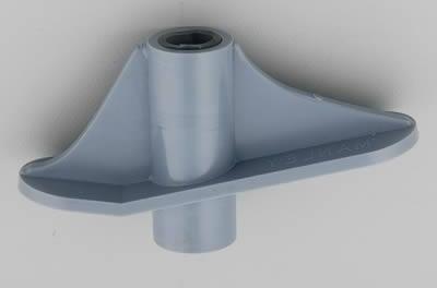
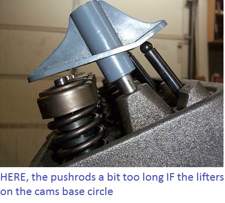
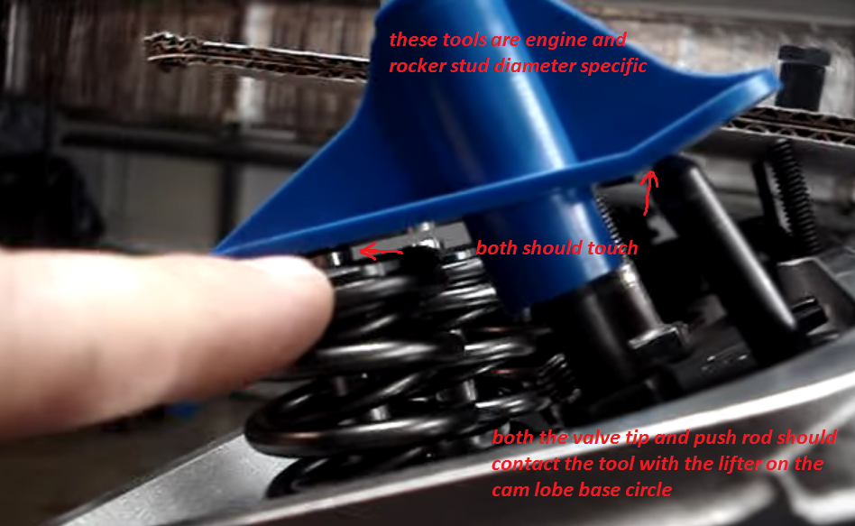
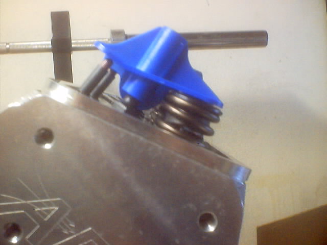
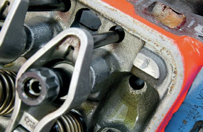
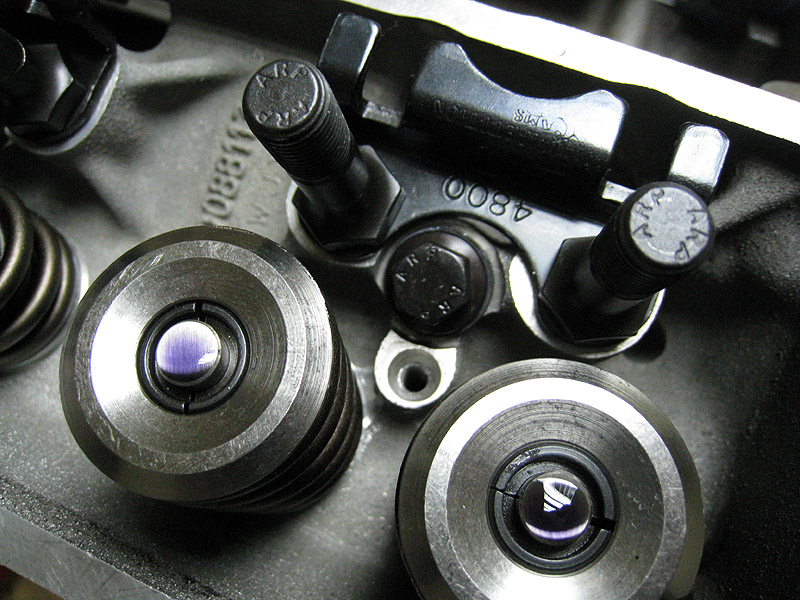
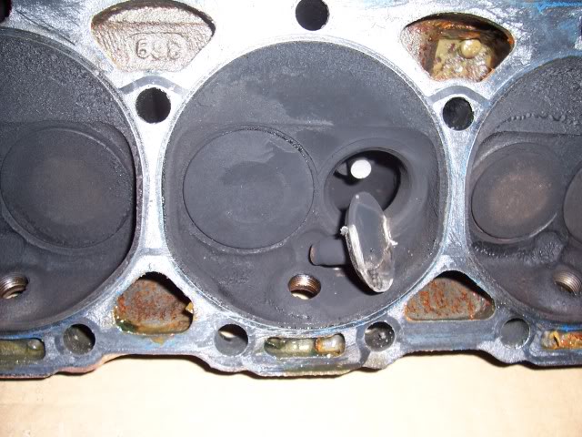
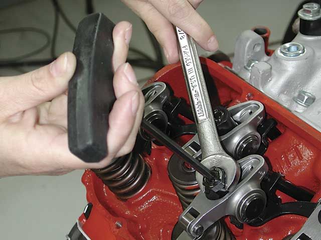
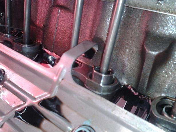
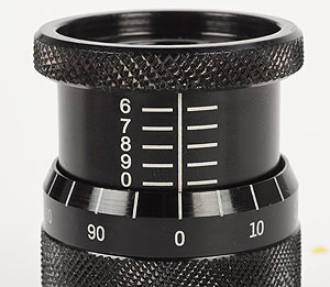
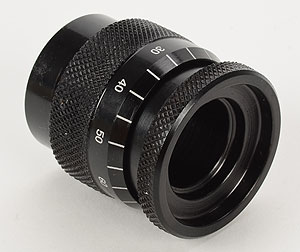
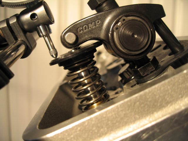
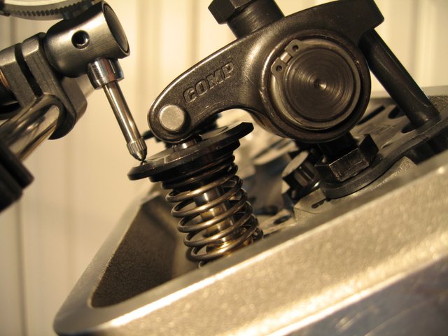
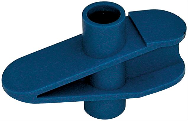
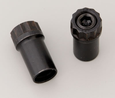
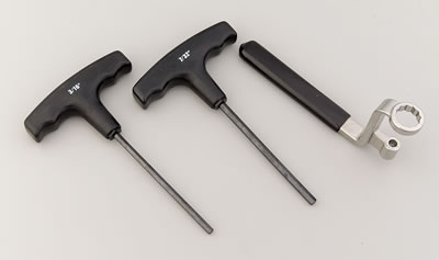
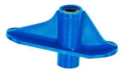
"THAT PLASTIC THING" is a PUSH ROD LENGTH CHECKER, THE PUSH ROD LENGTH CHECKING, AND ROCKER GEOMETRY TOOL, ARE ENGINE SPECIFIC, so you MUST USE ONE DESIGNED FOR THE SAME STUD DIAM. SPECIFICALLY FOR YOUR SPECIFIC ENGINE, to find the correct rocker geometry and push rod length. If you for example use one designed for 7/16" studs on a SBC and used it on a BBC with 7/16" rocker studs the result would not be close to correct, if the tool designed for one engine is used on the wrong engine, so be damn sure you use the correct tool.

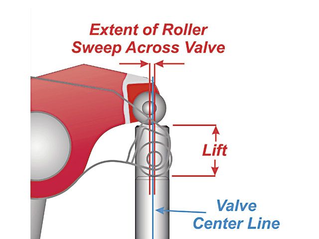
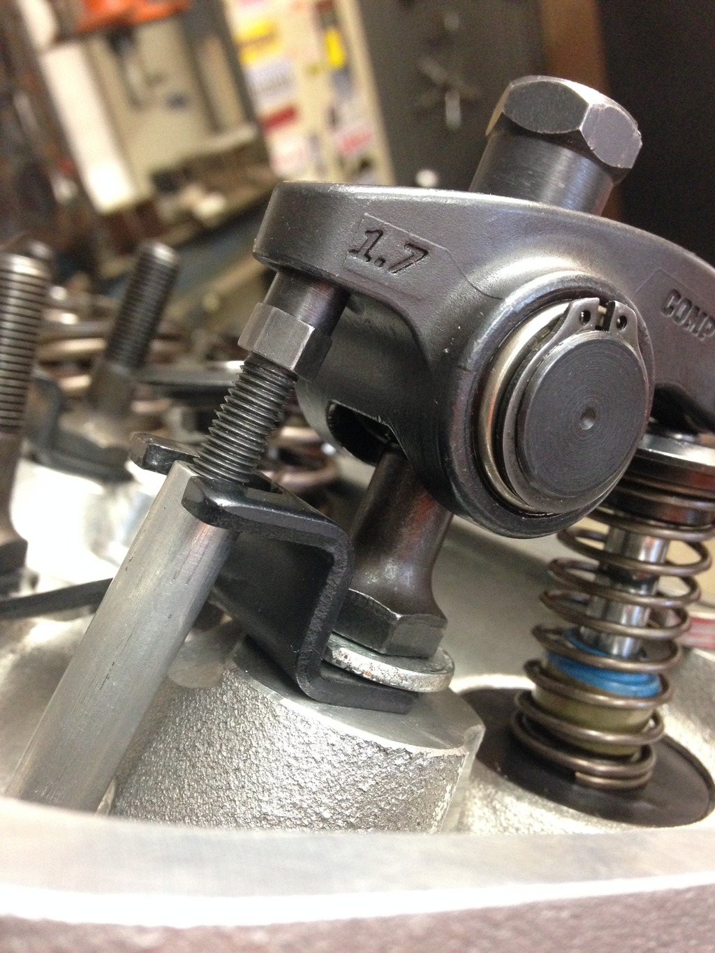
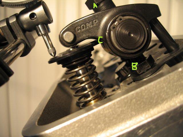
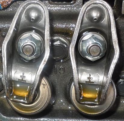
while your rocker wear marks on the valve tips look very close to ideal , you need to verify the push rod length, as getting that rocker geometry correct is important to durability , and a slight change in push rod length may improve that further, keep in mind that having the wear band centered is nice but not as important as keeping in narrow and close to center as possible as a narrow wear band tends to indicate minimal side thrust and as a result minimal wear results
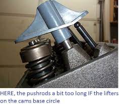
if your seeing a .120-.150 gap between the push rod tip when the "PLASTIC THING" is inserted on the rocker stud ,with the cam lobe /lifter on the base circle AND IF ITS THE CORRECT CHECK TOOL FOR THE APPLICATION,and its resting on the valve tip, your push rods that much too short for the application, your measuring, if the tool rests on the push rod tip and its lets say .060 off the valve tip, that indicated the push rods that much too long for THAT particular application, get within .040 or less on either meassurment and your fine
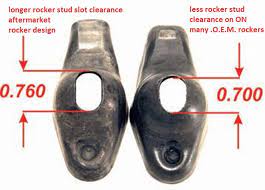
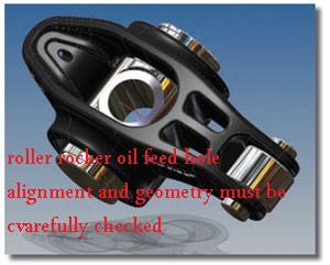
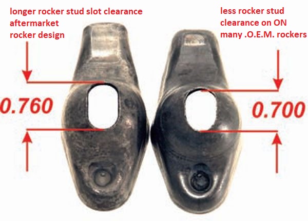
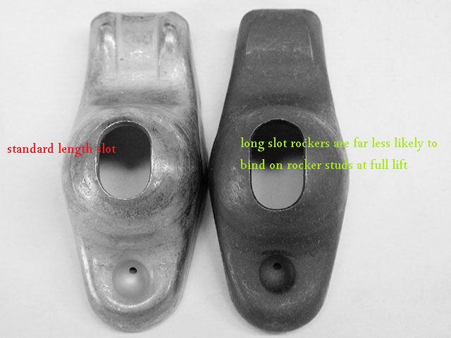
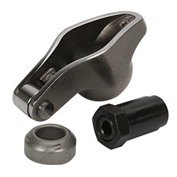
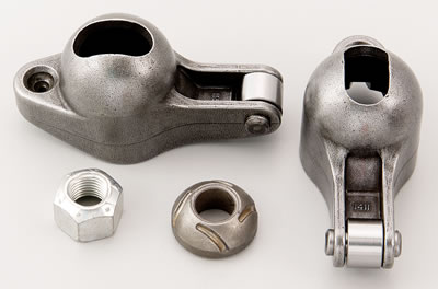
SOME ROLLER ROCKERS CAN AND DO BIND ON ROCKER STUDS, or rocker adjustment nuts, youll need to check carefully
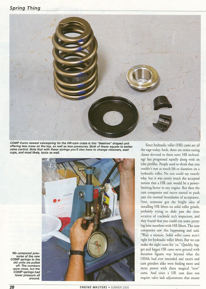
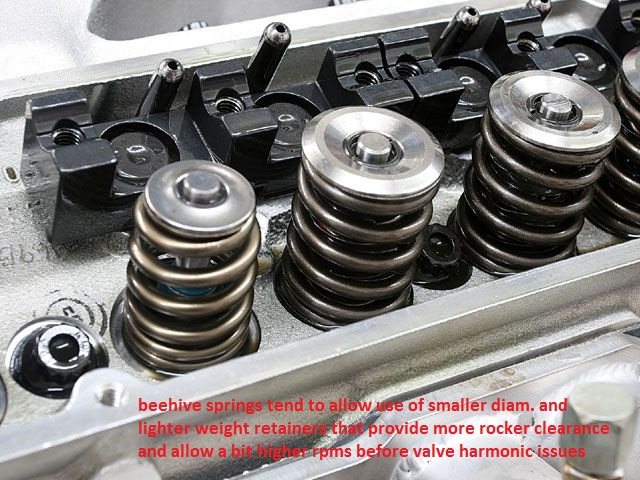
some roller rocker too retainer combo clearance issues cause problems easily solved with beehive springs and smaller retainer diameters
BEEHIVE SPRINGS GIVE A GOOD DEAL MORE ROCKER TO RETAINER CLEARANCE
https://www.youtube.com/watch?time_continue=93&v=SzD_LZ3fM-s
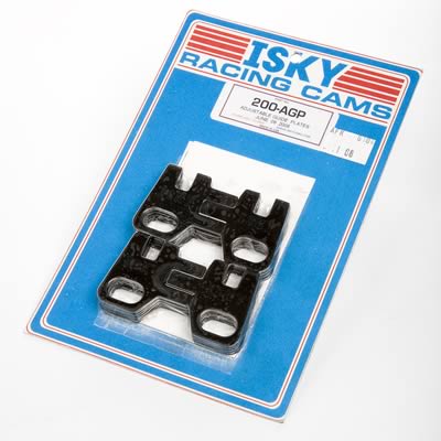
viewtopic.php?f=52&t=4596&p=18401&hilit=adjustable+guide+plates#p18401
viewtopic.php?f=44&t=2839&p=7344&hilit=adjustable+guide#p7344
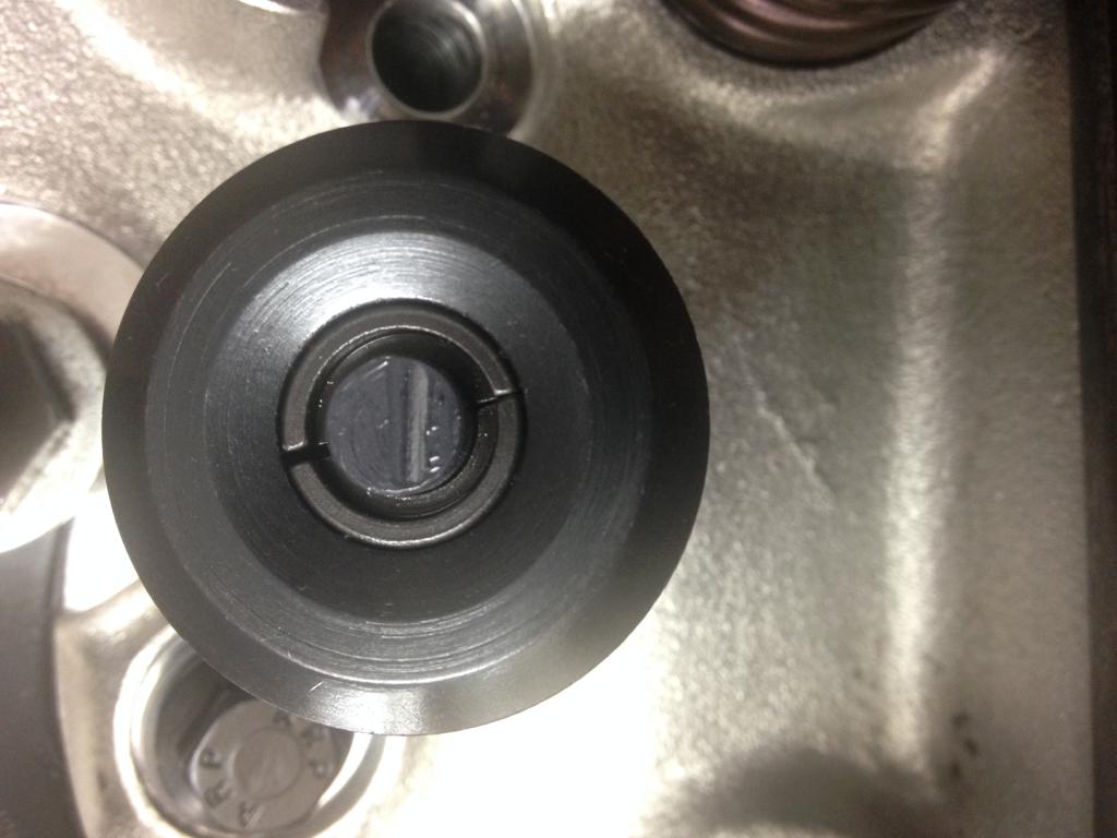
If your not getting oil flow, at the rockers,youll still need to verify the oil feed holes line up and are not blocked and the rockers adjusted correctly, try backing off on the adjustment nut as the engine idles to the point the rocker clicks noticeably then slowly tighten just to the point the noise stops , then add only a 1/4 turn, and see if that doesn,t cure the oil feed issue
this is what ERSON CAMS SUGGESTS AND MOST COMPANY'S
HAVE VERY SIMILAR PRESSURE SUGGESTIONS
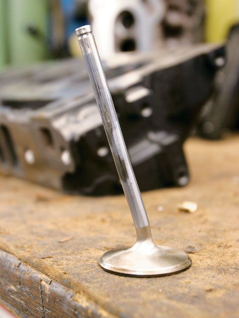
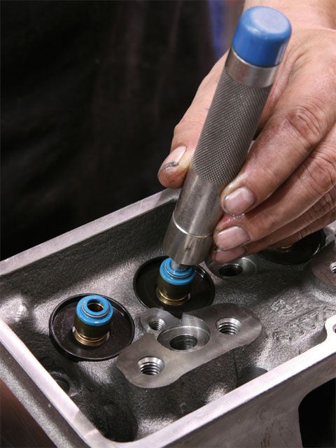
Id also point out that youll want to lubricate any valve you install in a valve guide and verify the valve train clearances very carefully, and use the correct valve springs and add the correct valve seals installed
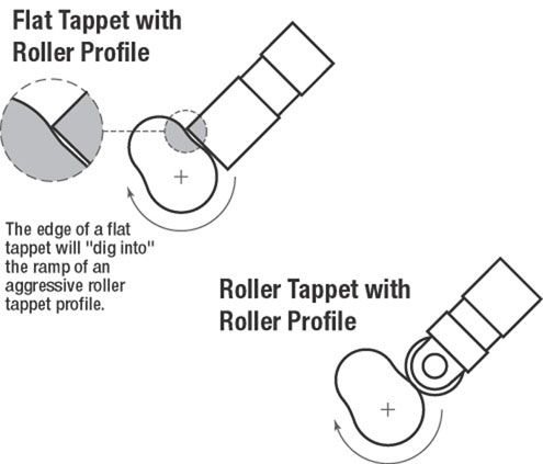
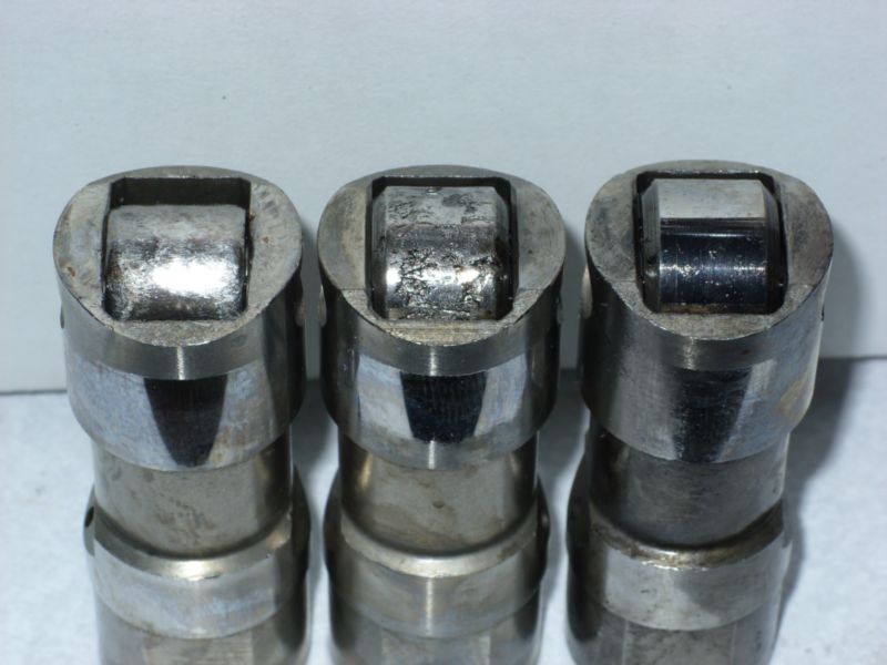
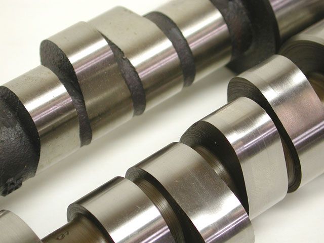
roller lifters are generally heavier than flat tappet lifters and roller cams tend to have more aggressive ramp speeds requiring stiffer valve spring load rates
The following recommendations are from Erson Cams. If you have questions, you can reach their tech department at 800-641-7920.
Hydraulic Flat Tappet Camshaft: 110 lbs Seat pressure/250-280 lbs open pressure
Solid Flat Tappet Camshaft: 130 lbs Seat Pressure/300-325 lbs open pressure
Hydraulic Roller Camshaft: 130-140 lbs Seat Pressure/300- 355 lbs open pressure
Solid Roller Camshaft: (Minimum Safe Pressures DEPEND ON SEVERAL FACTORS)
Up to .600Ë valve lift: 200-235 lbs Seat Pressure/600 lbs open pressure
Over .600Ë valve lift: 250-280 lbs Seat pressure /100 lbs pressure for every .100Ë of valve lift
http://garage.grumpysperformance.com/index.php?threads/lifter-weights-and-its-effect-on-rpm.16731/
CAST CAM CORES ARE NOT DESIGNED TO HANDLE OVER ABOUT 130lbs SEAT and 400lbs OPEN SPRING LOADS YOU NEED A BILLET CAM CORE FOR DURABILITY IF THOSE LIMITS ARE EXCEEDED
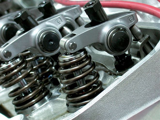
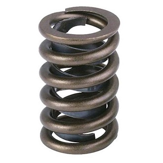
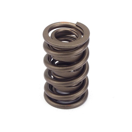
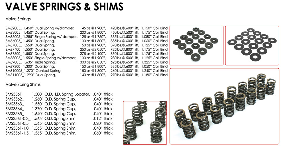
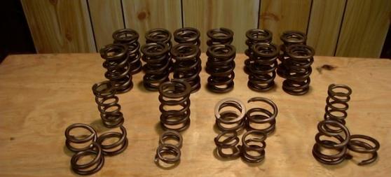
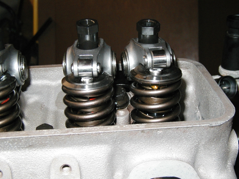
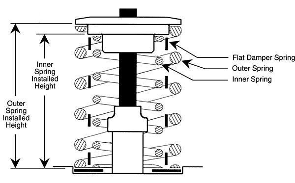
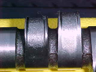
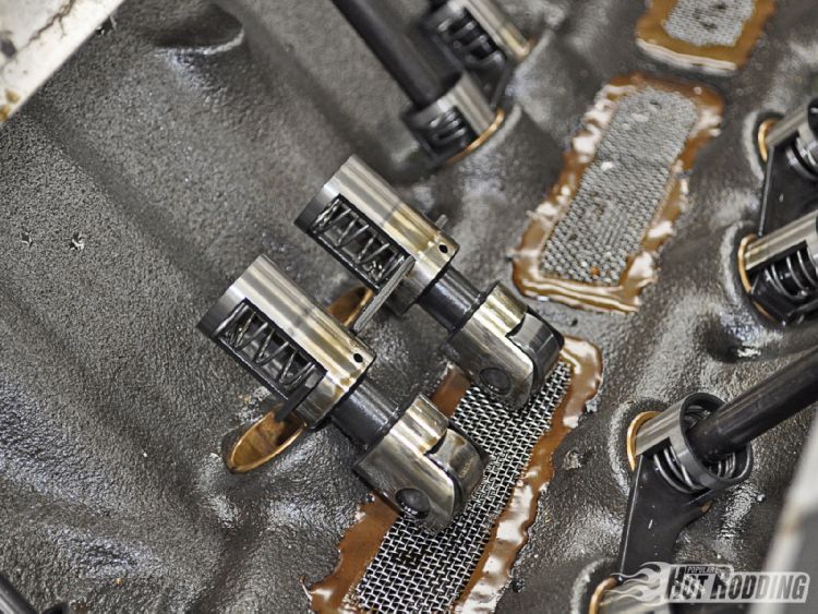
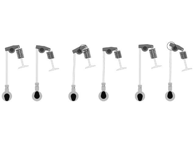
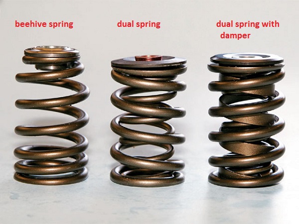
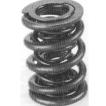
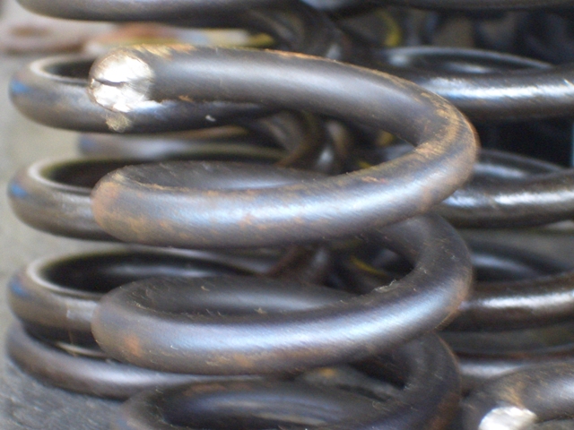
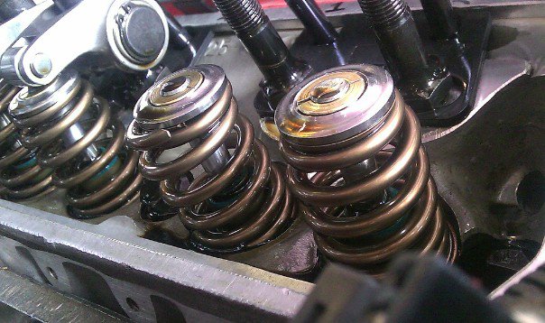
typically chevy valve springs use single or dual valve springs usually with an inner friction damper
single valve spring with friction damper
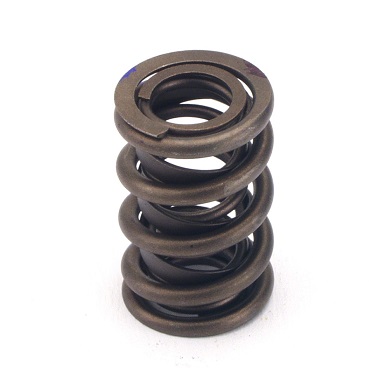
dual valve springs with friction damper
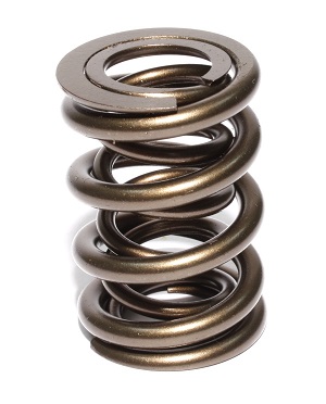
dual valve springs without damper
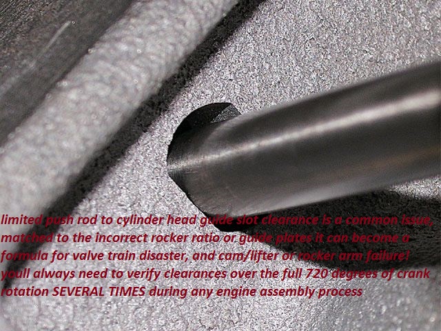
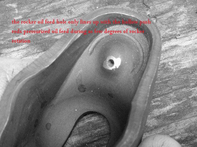
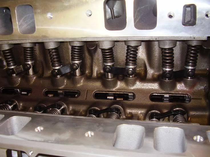
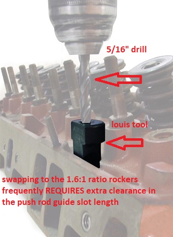
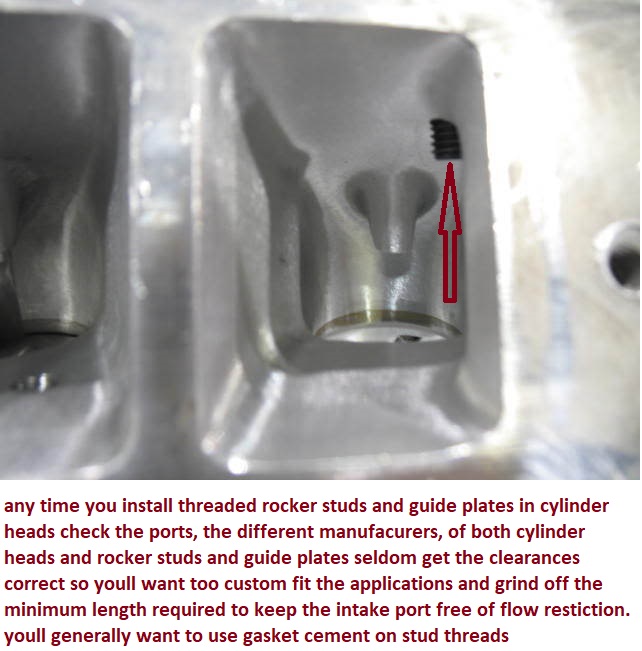
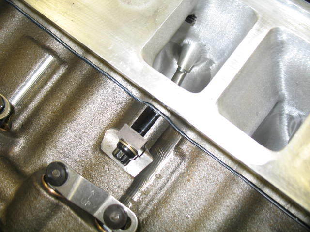
REMEMBER TO CAREFULLY CHECK THE PUSH ROD TOO CYLINDER HEAD GUIDE SLOT AND CYLINDER HEAD CASTING CLEARANCES,IF THE PUSH ROD BINDS IT MAY CAUSE A LOSS OF OIL FLOW THROUGH THE PUSH ROD, FROM LIFTER TOO ROCKER OR THE LIFTER TO WEAR RAPIDLY
checking all valve train clearance issues in mandatory
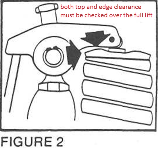
you must check EVERY ENGINE you assemble,or change valve train components on, for valve spring coil bind, on all springs and dampers,retainer to valve guide clearance,rocker to retained edge clearance, rocker slot to rocker stud clearance,the correct centered rocker to valve tip geometry , piston to valve clearance,push-rod to push-rod guide alignment and clearance , the heads for clearances and a dozen other factors listed below over the whole 720 degree repetitive cycle the valve train cycles thru
obviously you need to verify all valve train clearances and prevent parts binding at any point in the 720 degree repeat cycle the valve train operates in and you need to try to maintain almost all valve train geometry to minimize side loads on valve stems in guides to reduce wear and friction, and keep the lubricant flowing to absorb and remove heat from the valve train components
http://www.gsproducts.com/pac-valve-springs/
http://www.summitracing.com/parts/PRO-66789/
http://www.summitracing.com/search/Part ... -Checkers/
http://www.northernautoparts.com/Produc ... ductId=678
http://www.psisprings.com/index.php?opt ... view&id=17
http://www.cvproducts.com/Products/Engi ... %20Spring/
http://www.gsproducts.com/pac-valve-springs/
WATCH THE VIDEOS, READ THE LINKS
http://www.youtube.com/watch?v=Cqx8Cs6O ... re=related
http://www.youtube.com/watch?v=5GBNLlsi ... re=related
http://garage.grumpysperformance.com/index.php?threads/small-base-circle-cams.3810/
IT WILL HELP A great deal if you,READ THRU THE LINKS AND SUB LINKS
http://www.supercarsunlimited.com/info/ ... prings.htm
http://www.compcams.com/Products/CC-%27 ... %27-0.aspx
http://www.hotrod.com/techarticles/engi ... ewall.html
http://www.summitracing.com/parts/cca-7 ... dia/images
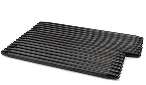
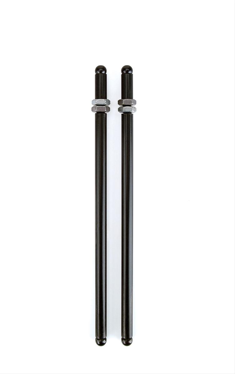
a good set of big block chevy push rods can easily cost over $200-$300
READ THIS THREAD
http://www.hotrod.com/techarticles/engi ... vesprings/
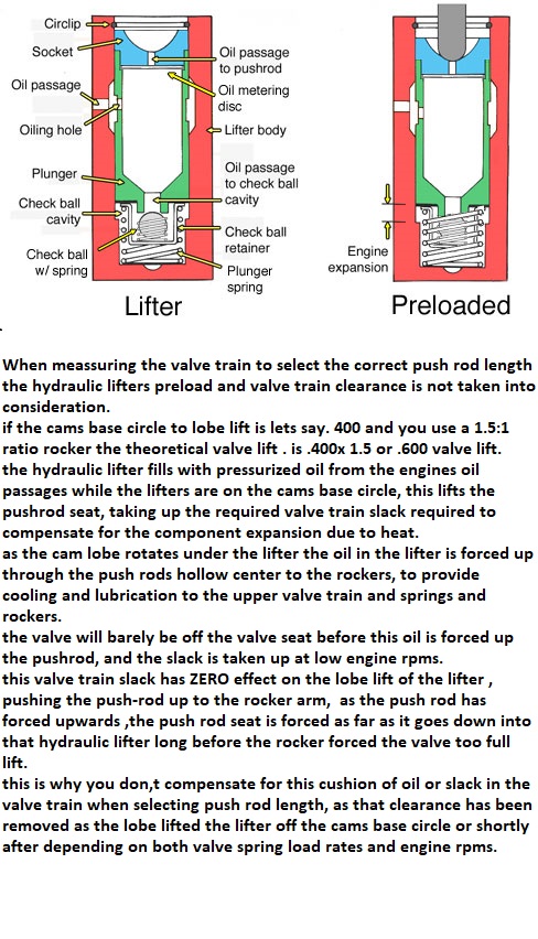
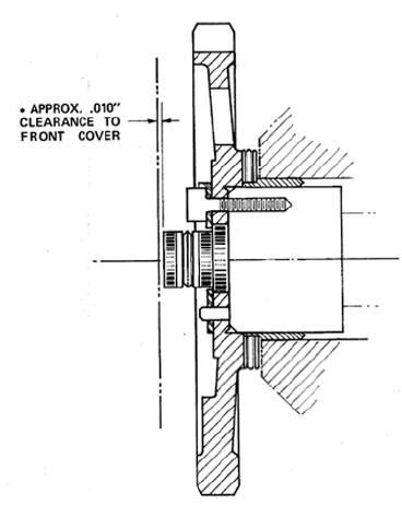
Proper push rod length is absolutely critical for peak performance—minimizing bent or broken valve stems, guide wear, and energy-wasting valve side-loading friction.
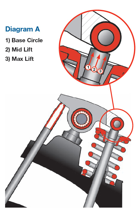
With the lifter located on the round base circle, position the Push Rod length Checker (make sure you have the Checker with the proper diameter hole) over the stud. Ideally the Checker should contact the top of the push rod and the valve tip evenly at the same moment, should the Checker contact the push rod first, measure the gap between the front of the checker and the valve tip, and purchase a shorter push rod of the correct length. Should the Checker contact the valve tip first, measure the gap between the back of the Checker and the top of the push rod, and purchase a longer push rod
http://www.summitracing.com/search/...d-length-checkers?autoview=SKU&ibanner=SREPD5
Proform Pushrod Length Checkers 66789 SBC 3/8" rocker studs
Proform Pushrod Length Checkers 66790 SBC 7/16" rocker studs
Proform Pushrod Length Checkers 66806 BBC 7/16" rocker studs
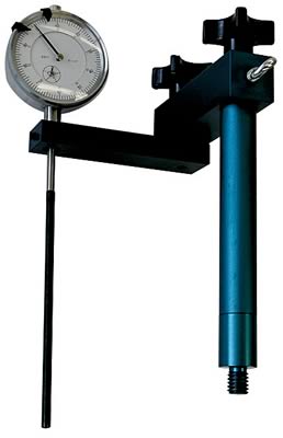
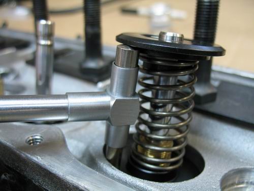
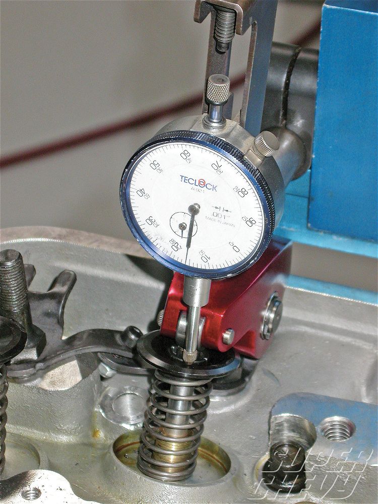
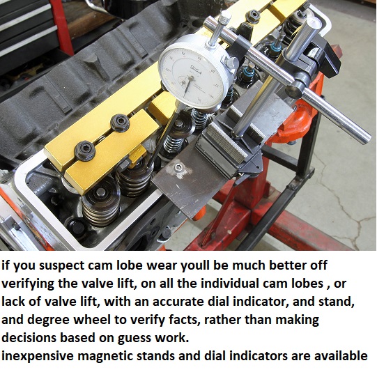
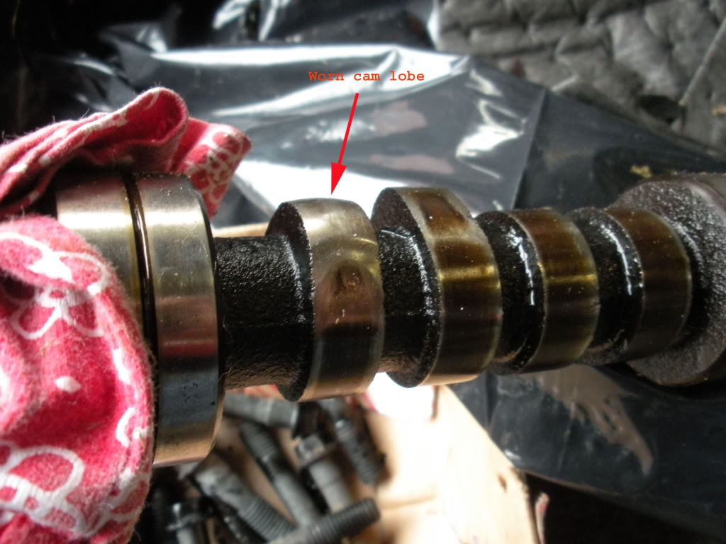
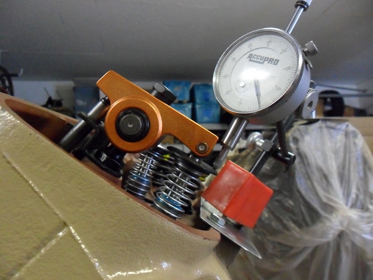
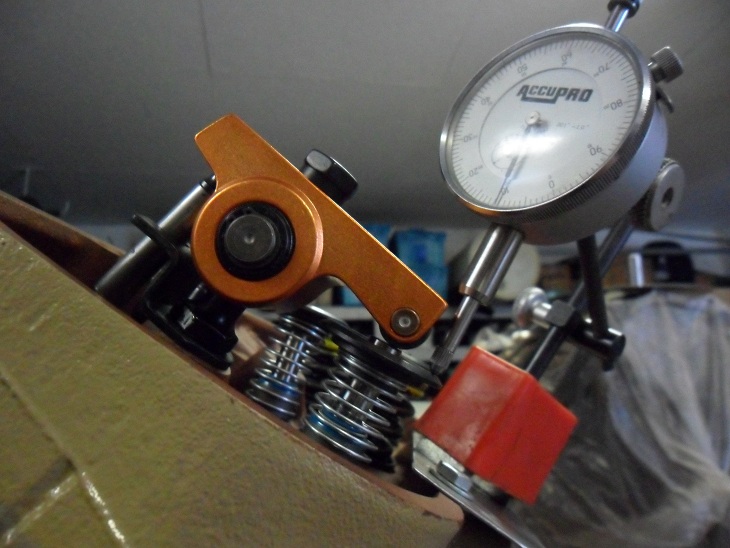
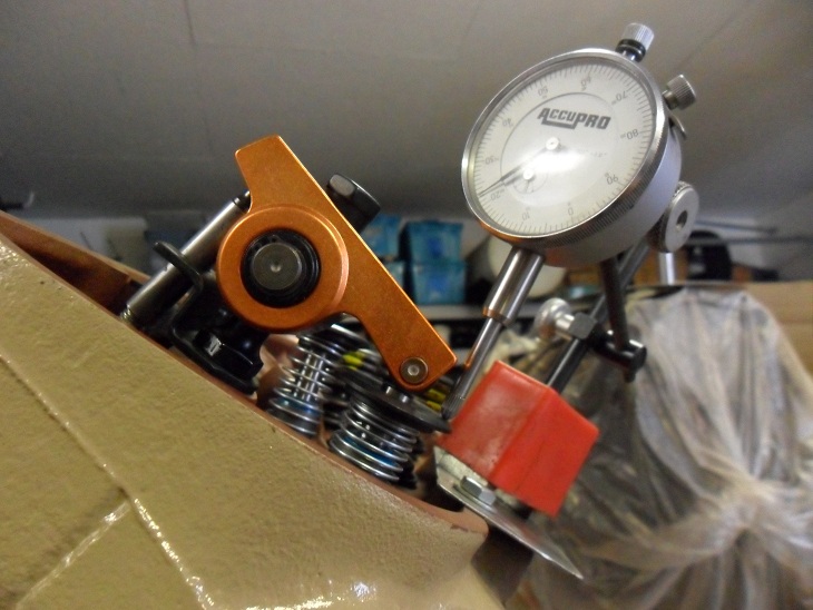
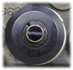
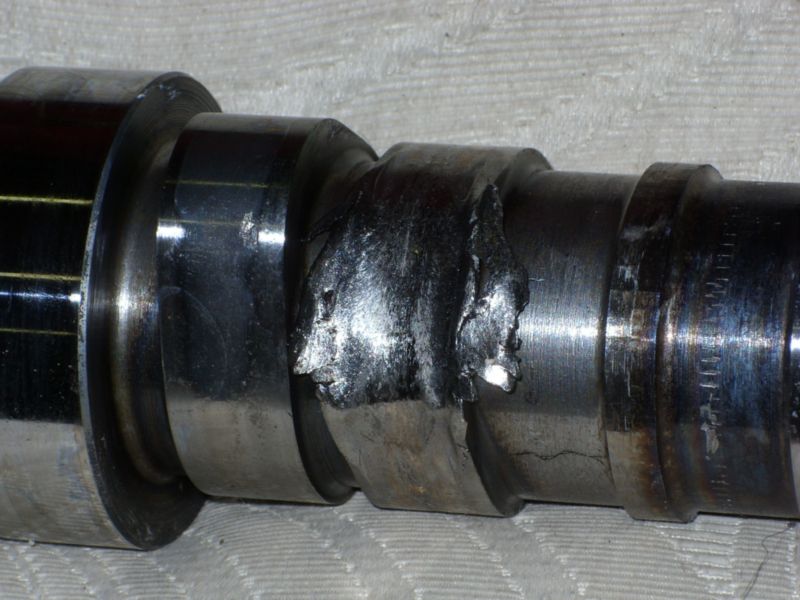
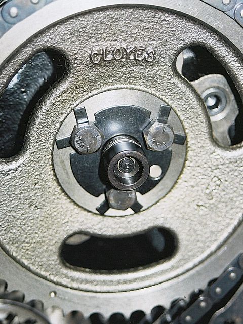
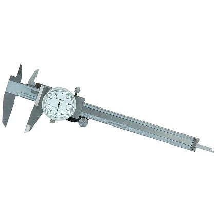
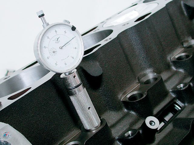
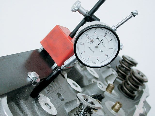
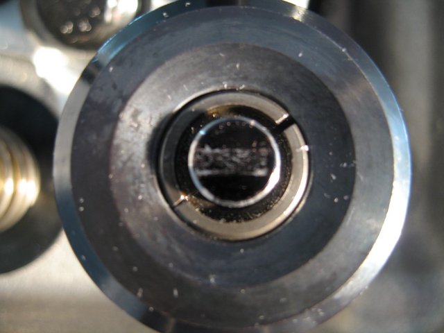
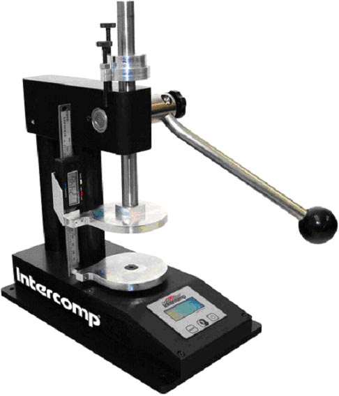
If you suspect a worn cam lobe, checking the cams lobe lift with a dial indicator on the valve spring retainer vs the other lobes would certainly provide useful related info.
knowing vs guessing helps in making decisions wisely
http://www.summitracing.com/parts/pro-66830/overview/
https://www.harborfreight.com/multipositional-magnetic-base-with-fine-adjustment-5645.html
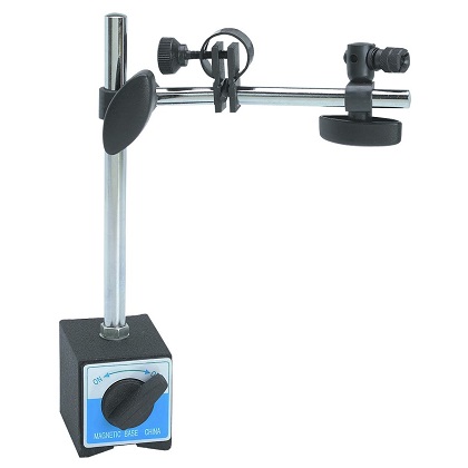
https://www.harborfreight.com/catalogsearch/result/index/?dir=asc&order=EAScore,f,EAFeatured+Weight,f,Sale+Rank,f&q=indicator+stand
http://www.racingsprings.com/
(866) 799-9417
http://www.racingsprings.com/Staff
heres their ph#
Toll Free (866) 799-9417
I always just order the springs retainers valve locks and spring seats as a package deal (NOT CHEAP BUT EVERYTHING WORKS AND FITS) then you just need shims under the valve spring seats occasionally to get the correct installed height
http://www.racingsprings.com/Valve Springs/Store/13
http://store.procompelectronics.com/p-1 ... of-16.aspx
I buy most of the valve springs I use from these guys, if you tell them EXACTLY what you are doing , clearances, cam, spring diam, length etc. they can suggest something that fits your application almost EXACTLY, they are usually very helpful
I usually buy valve springs from these guys
http://www.racingsprings.com/Store/ProductCategory.asp?ProductCategoryID=13
if your not sure what you need in load rates and clearance and installed height,ETC., ask the tech guys on both that site and your cam manufacturers site.
in an ideal world the rocker pushes strait down the valve stem center line to reduce friction,but having the rocker wear pattern centered on the valve tip is far LESS important than having it rather narrow indicating less side thrust or drag on the valve
and having the rocker geometry a bit off as long as the clearances are correct, is unlikely to cause noise issues as much as long term valve guide wear issues
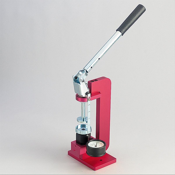
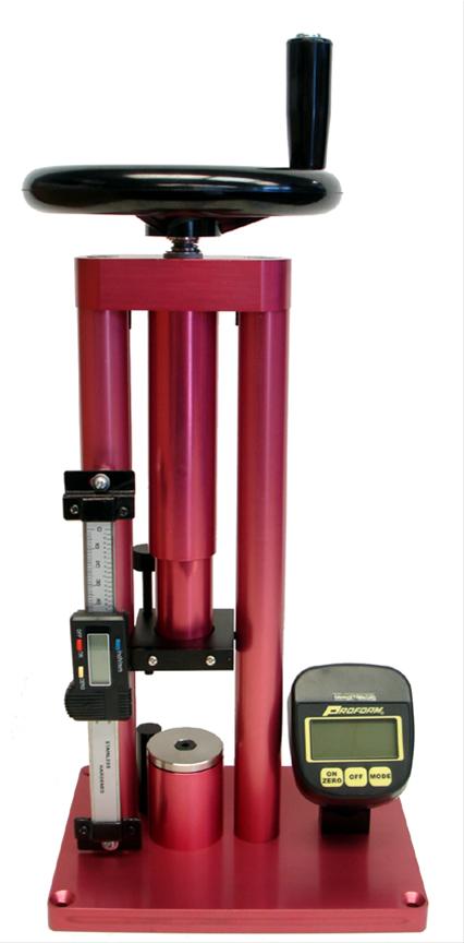
http://www.summitracing.com/parts/CCA-7901-1/
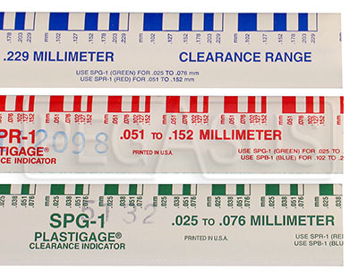
actually measuring clearances helps a great deal

http://www.summitracing.com/parts/PRO-66832/?rtype=10
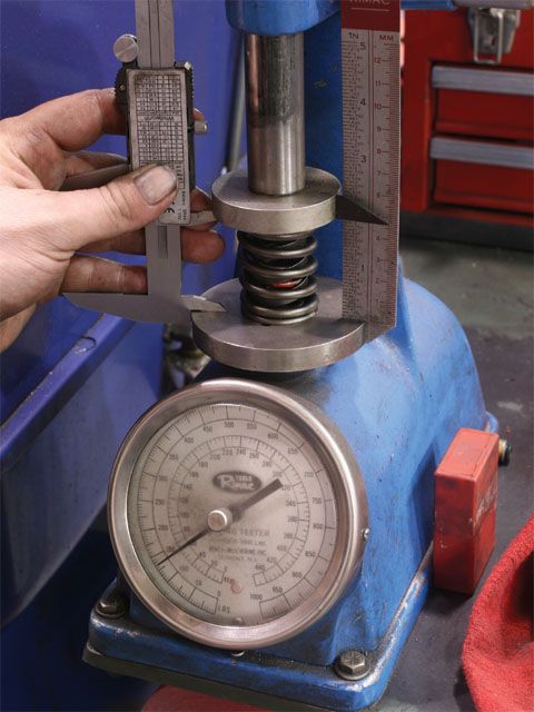
If your not sure about the proper installed spring height,spring load rates,valve shims ,valve spring seat and required clearances,why not have the machine shop suggest what would match your current needs after telling them the clearance requirements and cam lift.
remember longer valves generally require longer push rods and getting the rocker geometry correct is critical to durability, shims & spring seats can easily be used to shorten installed spring heights,they also make .050 off set valve keepers and .050 off set spring retainers so you can adjust installed height over a full .200 with the same valve length
READ THESE
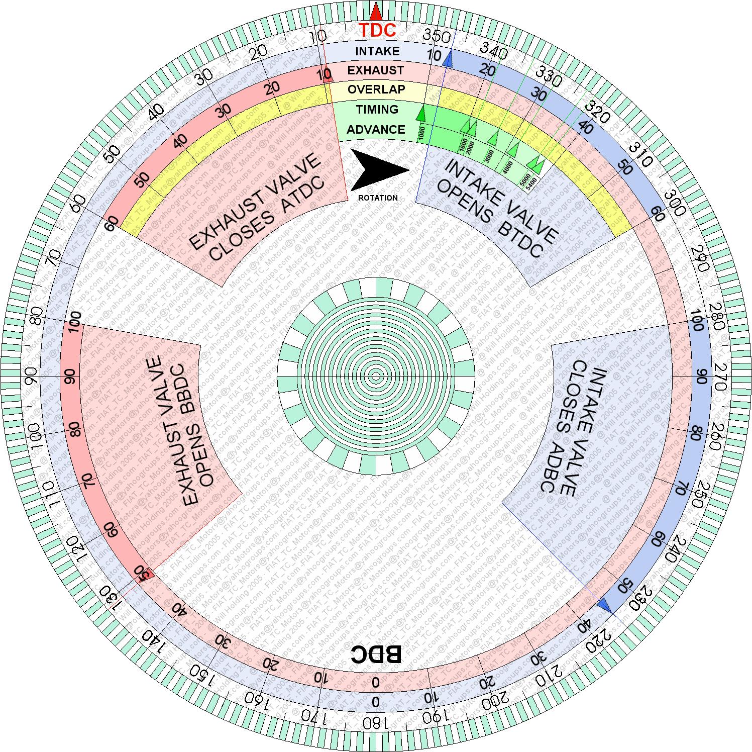
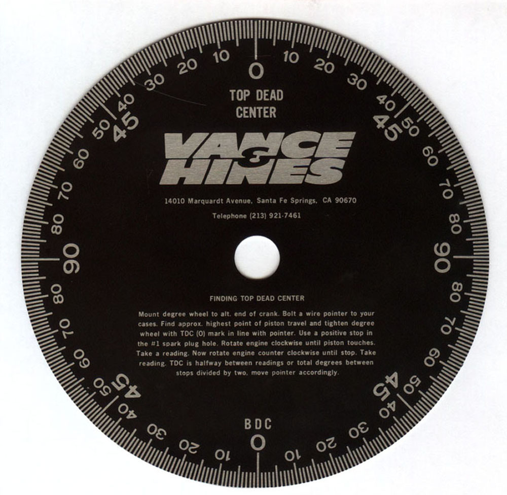
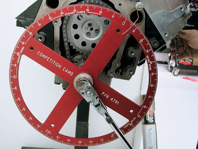
heres a printable degree wheel
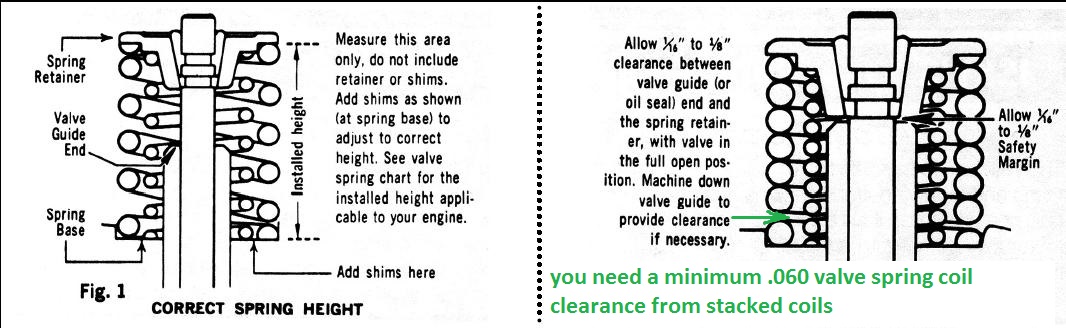
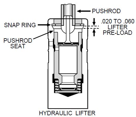
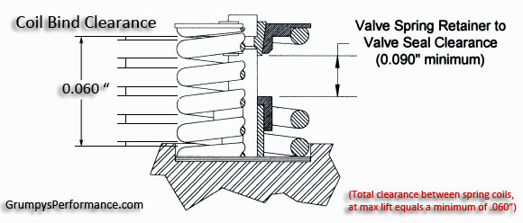
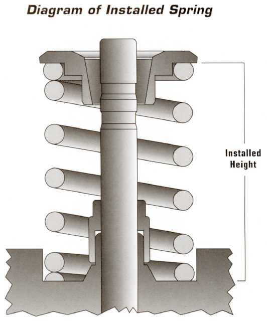
INSTALLED SPRING HEIGHT-MINUS SPRING BIND HEIGHT-minus .060 thousands -EQUALS MAX LIFT
http://www.enginebuildermag.com/Article ... _much.aspx
http://www.kennedysdynotune.com/Valve%2 ... 20Tech.htm
READ THRU THESE INFO LINKS ALSO, THERE A GREAT DEAL OF USEFUL INFO IN THE LINKS, and SUB-LINKS POSTED HERE THAT YOU NEED TO KNOWyes IM sure that appears to be a huge investment in time and effort , but having a durable and stable valve train takes a bit of effort and knowledge to set up correctly, you can rarely just assemble parts and have it work correctly.
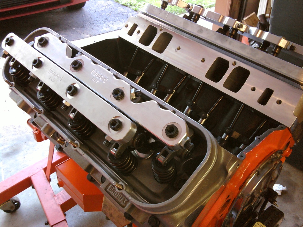
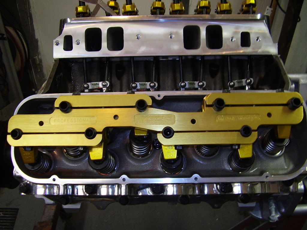
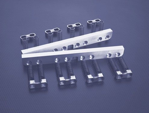
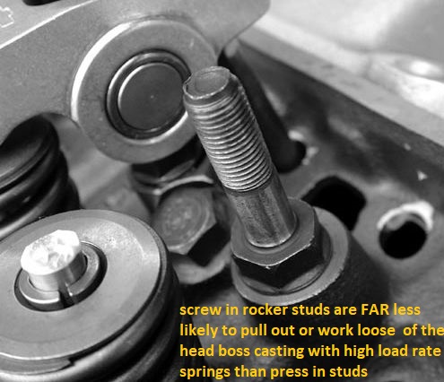
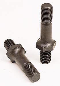
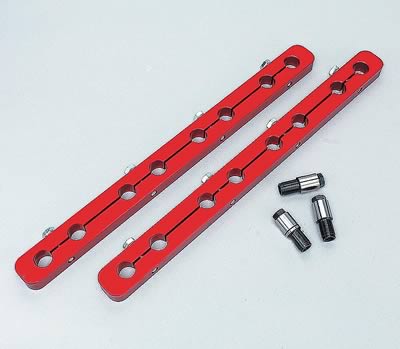
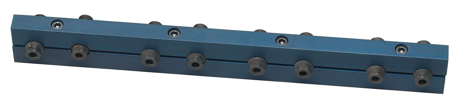
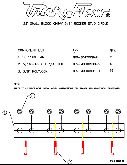
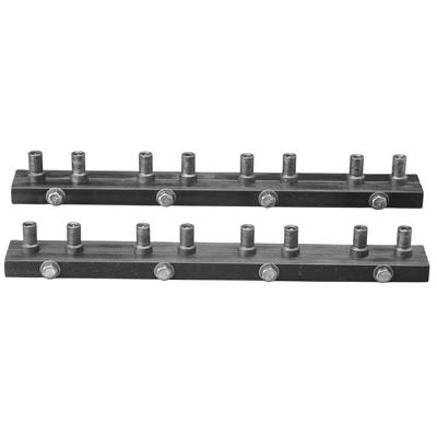
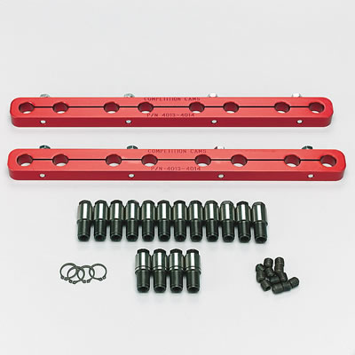
If your thinking of running over 450 lbs or valve spring at peak lift Id suggest both 7/16" rocker studs and a stud girdle , be used and if your running 500lbs-600 lbs plus of spring pressure , its pretty much mandatory,on both a sbc and bbc
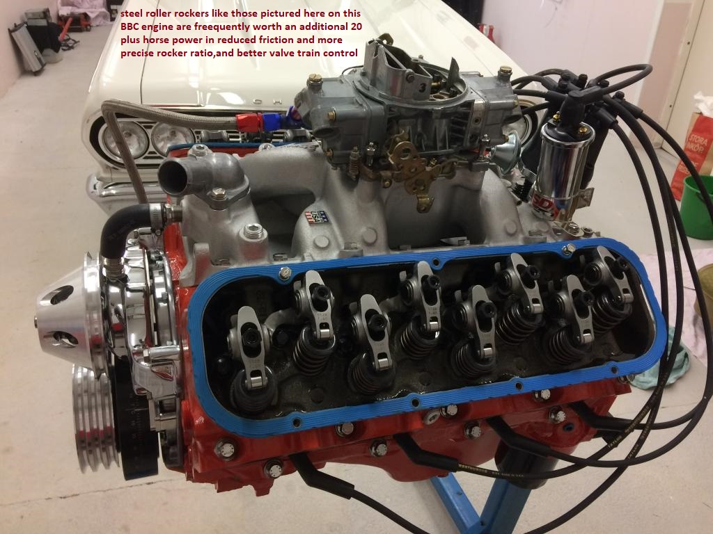
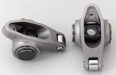
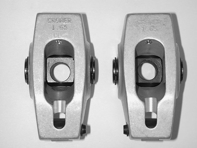
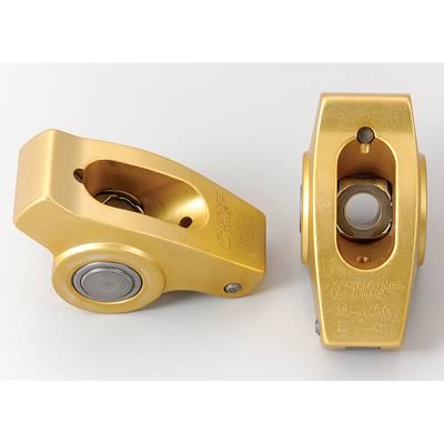
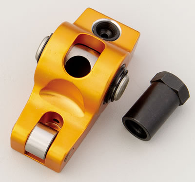
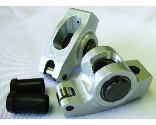
and Id suggest the STEEL ROLLER ROCKERS,be used rather than aluminum as they have a longer fatigue life, the last thing you want is a rocker stud cracking a head, or a rocker coming apart at high rpms
in theory brass/bronze valve guides are minimally softer and wear faster,than iron valve guides, but in reality if your using the proper valve seals, and have your oil flow to the upper valve train functioning correctly with reasonably clean oil, theres a thin coat of oil between the valve stems and the surface of the inner valve guides, that prevents any wear if your valve train geometry has the main loads centered on the valves center line. keep in mind having proper valve train geometry, and having constant clean oil flowing over and cooling the valve springs, and rockers, plays a huge part in valve wear issues.remember the surface Finnish, clearances, valve seals and oil viscosity along with proper valve train geometry and material used in the valves also effects valve wear
btw coating the valve stems with a mixed slurry of marvel mystery oil and crane cams MOLY assembly lube during the cylinder head assembly process, tends to prevent dry start issues with the guides seizing valve stems
(quote)A valve spring not only has to control the valve train, but also the spring's own weight. So
reducing the weight of the moving end of the spring helps in this matter.

Rick(quote)
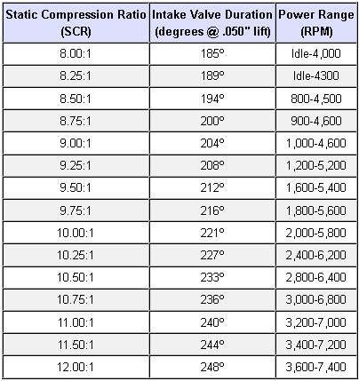
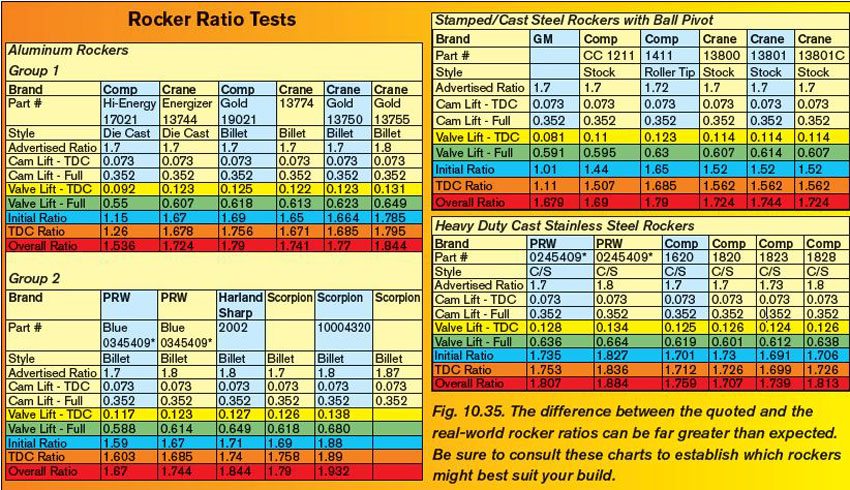
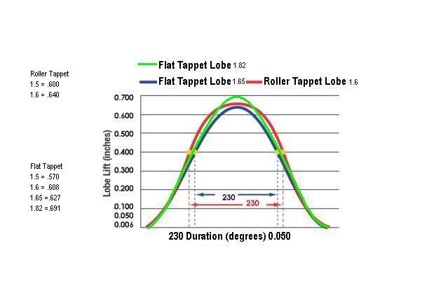
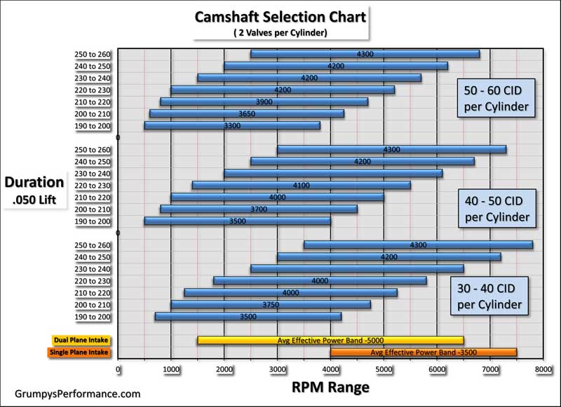
heres a chart I found that I don,t fully agree with, I think its a bit conservative, by about 3%-5% on the required cam duration ,required to avoid detonation with todays crappy octane fuel, but it at least gives you a base to work from, but Id suggest selecting a bit more duration
YOUR REALLY GOING TO WANT TO READ THRU THESES SUB LINKS FOR MORE COMPLETE INFO
http://www.compcams.com/technical/FAQ/F ... prings.asp
http://www.pontiacstreetperformance.com ... ngeom.html
http://www.hotrod.com/techarticles/engi ... vesprings/
http://www.carcraft.com/techarticles/vo ... index.html
http://carcraft.automotive.com/9794/vor ... index.html
http://www.supercarsunlimited.com/info/ ... prings.htm
http://www.hi-flow.com/HPYT4.htm
http://www.kmotion.biz/instht.htm
http://www.carcraft.com/techarticles/11 ... index.html
http://www.aa1car.com/library/camshafts.htm
http://www.compcams.com/catalog/COMP201 ... 010_10.pdf
http://www.chevyhiperformance.com/techa ... fters.html
http://garage.grumpysperformance.com/index.php?threads/valve-train-clearances-and-problems.528/
http://www.ovaltracking.com/tech/2006/i ... ive-3.html
http://www.vetteweb.com/tech/vemp_0204_ ... index.html
http://cranecams.com/?show=valveSpringsFAQ
http://www.compcams.com/Products/335-353.PDF
http://www.compperformancegroupstores.c ... re_Code=PH
http://www.cranecams.com/?id=5&show=faq
http://www.popularhotrodding.com/tech/0 ... index.html
http://www.corvetteflorida.com/forums/s ... php?t=5725
http://www.circletrack.com/drivetrainte ... index.html
http://www.circletrack.com/enginetech/c ... index.html
http://www.hotrod.com/howto/51058_cylin ... index.html
http://www.flatlanderracing.com/revkitsafr.html
http://www.powerperformancenews.com/for ... a-863.html
http://popularhotrodding.automotive.com ... index.html
http://www.stockcarracing.com/techartic ... index.html
http://www.supercarsunlimited.com/info/ ... prings.htm
http://www.chevyhiperformance.com/techa ... index.html
http://www.compperformancegroupstores.c ... y_Code=BEE
http://www.popularhotrodding.com/engine ... ables.html
If your rebuilding an engine ,the questions that really should be asked here......
were you completely happy with the old cam or did you feel you wanted more upper or lower rpm band torque, did you like the way the engine ran, or did you feel it needed some tweaking?.....
what would you have liked to be changed about the power band when the old grind was in use?
BTW are you aware that reducing cams lift and valve spring load rates /pressures, and the degree of the aggressive cam ramp acceleration tends to increase durability in valve train components? yes it may cost you some hp, but it may be a good trade for increased durability
thats something thats partly an art, not truly an exact science, due to differences in ramp acceleration rates, lifter design, and valve train geometry, spring load rates,harmonics, etc. I usually contact the cam manufacturer and get their input,, because they are very much interested in having their product perform well. then I carefully verify my combos clearances and spring load rates,(verifying the clearance issues are VERY important) but you need to understand that if you substitute a different brand or style of lifter or rocker,etc. its going to change the results, harmonics and rpm band, generally you can add some stability with a rocker stud girdle, and if you find your having control issues you can usually either add a rev kit or swap to a slightly stronger load rate in a beehive or dual spring.
you might want to look into BEE HIVE VALVE SPRINGS, because, if they are available for your application. they allow both a lighter spring with the same pressures and a smaller diam, and lighter weight retainer , giving greater rocker clearance and lighter inertial loads at high rpm
lower spring pressures usually result in less wear on the valve train, smaller diam. retainers, used on bee hive springs generally allows higher rpms and lower loads on the valve train, IDEALLY, you want the LOWEST spring rates and LIGHTEST valve train components that will still control the valve train in the rpm ranges your engine operates in.
check with your cam supplier they tend to cost slightly more but they can give you some additional rpm capacity and lower stress
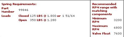
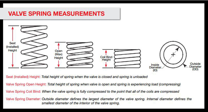
keep in mind the seat diam. on the heads is usually limited or set by what can be machined ,the coil bind or stack height and installed height must match the cam lift clearance and and both the open and stationary s, issues like inside dia. and distances between retainer and valve guides ETC. dictate the valve seals that can be used, spring loads must match the application, yes
when you select a cam, the cam supplier will generally suggest matched springs, and an installed height and matched components, and yes they have a marked interest in your engine performing well , so they will tend to give good info, they are NOT just trying in most cases ,to increase their profits by selling you stuff you don,t need.
yes stock springs are fine IN SOME APPLICATIONS, but you must ALWAYS check spring clearances and loads and valve train geometry
theres a big difference in spring quality between the O.E.M and the better aftermarket springs and running double or triple springs can at times be an option, remember lighter valve train components usually reduce stress, allow less spring pressure and resulting valve train wear, and tend to increase the rpm range.
btw your generally fighting a hopeless battle if your expecting complete valve control with any hydraulic cam design much over about 6400rpm-6500rpm
and your valve spring load rates do effect the roller lifters life expectancy, high load rates decrease the cams life span and increase wear issues
Smokey Yunick discovered that valve springs raise the operating temperature of engine oil more than combustion heat with his own version of today's "Spintron" spin fixture. From the Circle Track Archives
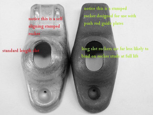
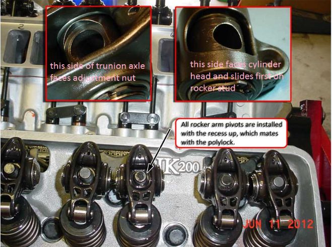
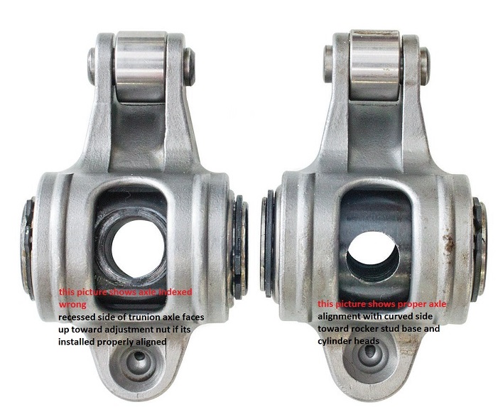
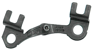
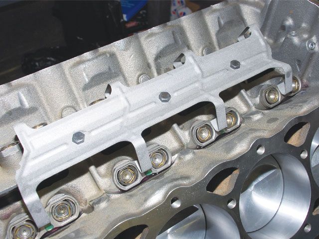
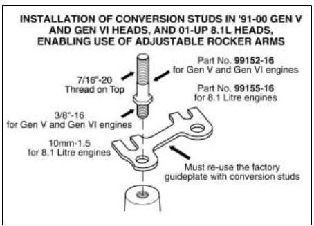
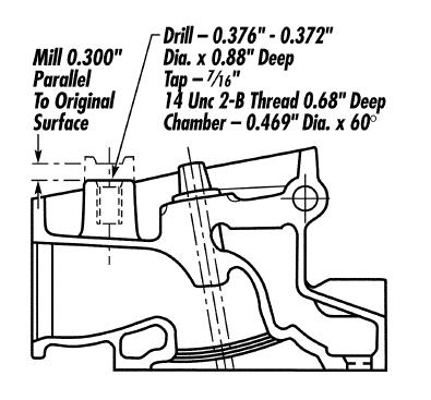
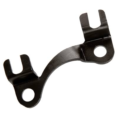
keep in mind that you can use EITHER self aligning rockers OR guide plates BUT NOT BOTH at the SAME TIME with properly installed screw in rocker studs
http://www.racingsprings.com/
http://www.iskycams.com/psisprings.php
http://www.psisprings.com/index.php?opt ... view&id=17
http://www.ovaltracking.com/tech/2006/i ... ive-3.html
self aligning rockers have ridges to prevent the rocker from moving off the valve stem


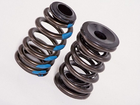
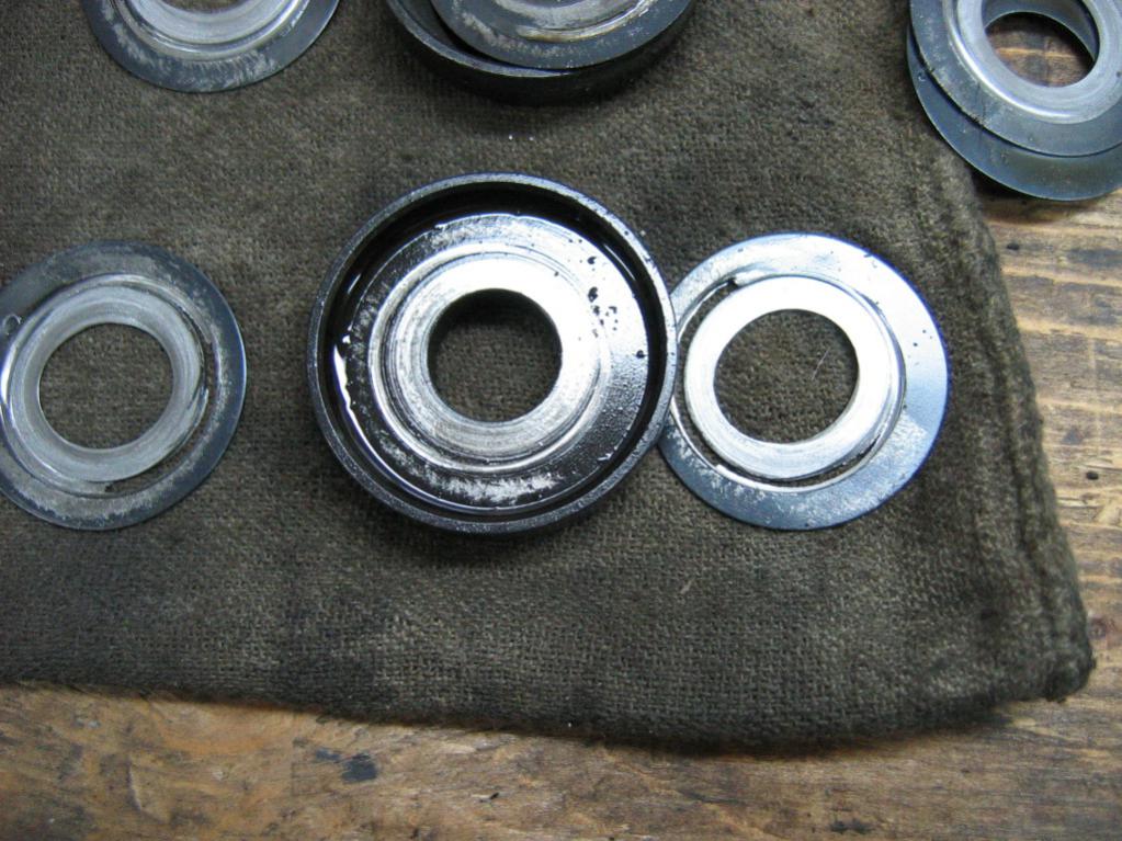
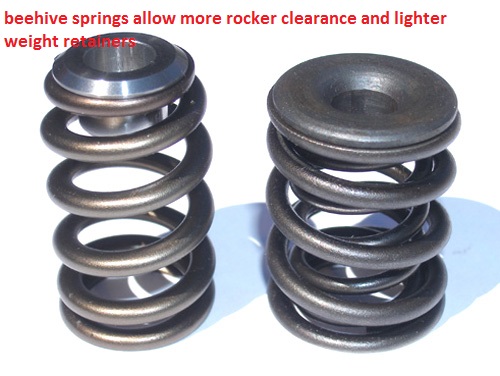
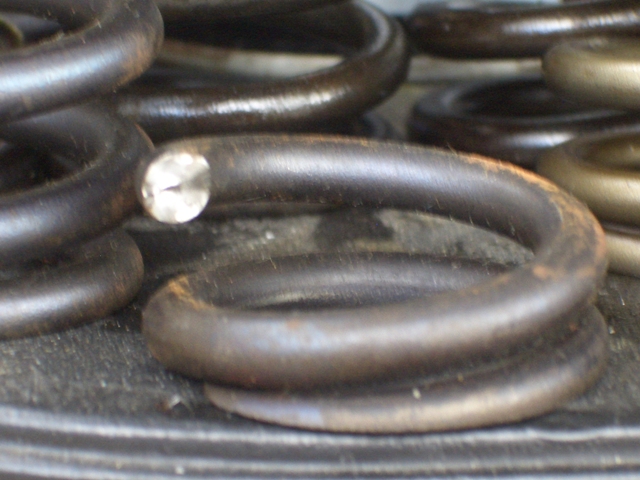
left is a BEEHIVE SPRING,with small light weight retainer, RIGHT SIDE STANDARD SPRING standard retainer
http://www.dougherbert.com/1445beehives ... 22853.html
http://www.jegs.com/webapp/wcs/stores/s ... 7_-1_10699
http://www.carcraft.com/techarticles/vo ... g_upgrade/

Id use any decent quality springs from any NAME BRAND manufacturer regardless of brand if the clearance and load rate specs matched the required clearances and loads, naturally the manufacturer of the cam has a vested interest in your engine running correctly so their advice should be taken seriously, but because its a very competitive market they will rarely point out the BEST springs, opting for the slightly more that adequate choice to keep the costs lower and make the sale, knowing that in most cases that's going to be the best compromise , but I certainly would avoid "deals" from sources like EBAY where your not sure what your getting and they have little to loose selling cheap imported junk, after all its YOUR engine that's going to be damaged if they fail, and quality COSTS more than JUNK!
as a general guide flat tappet cams , and mild hydraulic roller cams will want about a 120 lb seat and 330-340 lb over the nose full open spring load rates
its not until you get into the solid roller cams that the load rates jump significantly
naturally you'll want to read the cam manufactures info on clearances, posted on the cam cards and their web sights , as to suggested installed height, spring diam. and load rates before selecting springs or setting up your clearances and the installed heights and spring bind heights do vary a good deal, and don,t forget to verify the valve train clearances and geometry, as a general rule, sbc hydraulic cams used with stock heads,will work with lifts of 0.475 and under, and work with most stock springs
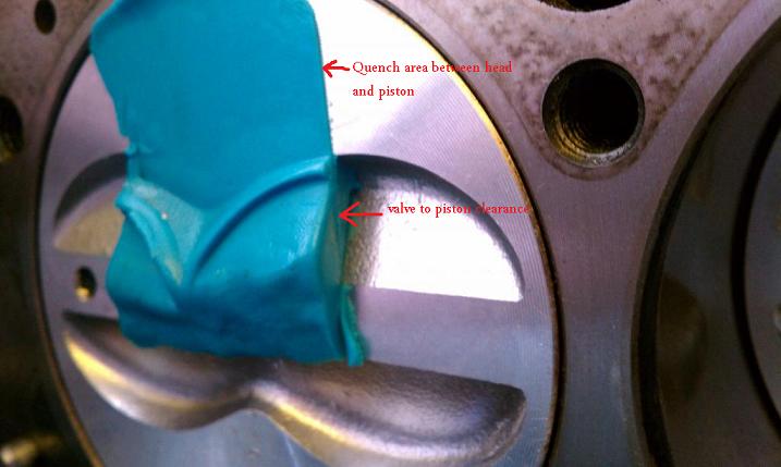
yes we all know guys who (SUCCESSFULLY??) installed a .500 lift cam with good result (SO FAR), but without checking clearances carefully that also a great way to have problems, and its that not checking that results in most of the problems I constantly see, as a result of cam swaps, youll also want to keep in mind that the DURATION and LSA (LOBE SEPARATION ANGLE) play a part in the clearance issues, between the valves and pistons
obviously getting the clearances wrong, or over reveing the engine can cause problems
http://www.summitracing.com/parts/pro-66830

http://www.centuryperformance.com/check ... g-144.html
http://www.racingheadservice.com/Inform ... arance.asp
http://www.cdxglobal.com/content/sample ... ear_WS.pdf
http://www.chevyhiperformance.com/techa ... index.html
http://www.carcraft.com/howto/116_0701_ ... index.html


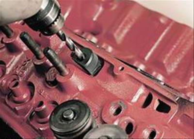
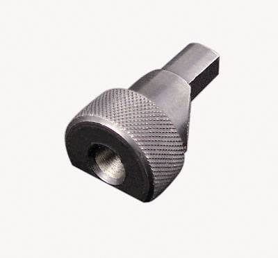
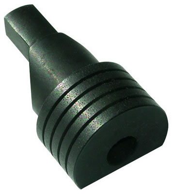
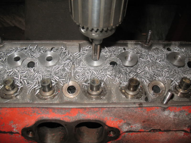
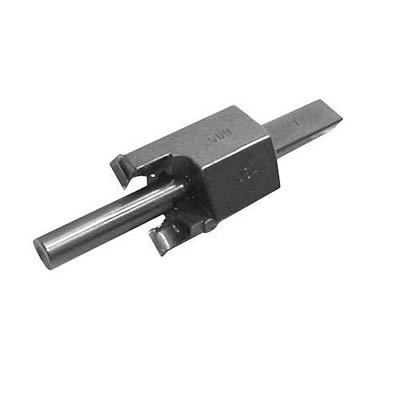
ISKY CAMS SELLS CUTTERS LIKE THIS TO NOTCH PISTONS

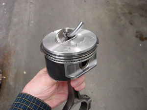
there's hundreds of ways to destroy an engine, but a common route is trying to compress solid objects in the combustion chamber where there's not nearly enough clearance, or having the valve train bind up due to clearance issues or reeving the engine above its valve control limitations. lack of lubrication and too much heat can easily be factors but...
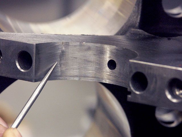
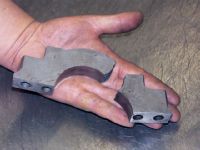
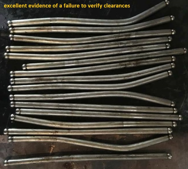
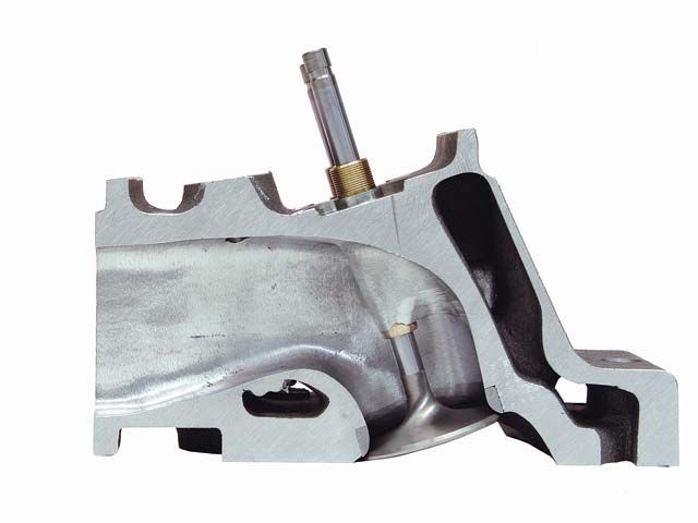
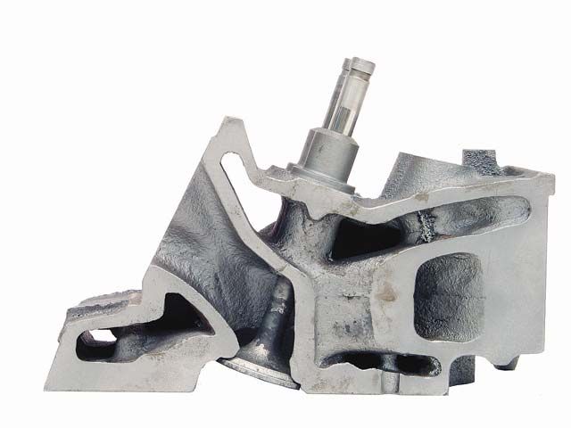
failure to keep the pistons from hitting the valves, bending valves, ,over reeving the valve train and having un-controlled valve movement, or having chunks of piston ,that detonation can break loose, being compressed against the heads can result in the cracked cylinders, and bent rods like the pictures below show
any part can fail but running valve springs up near their minimum clearance and maximum rpm range limitations is just asking for problems
It might take you several hours to read thru all the links and sub links but its time very well spent as it could save your engine from destruction and save you thousands of dollars
ALWAYS ask detailed questions as to the best , and most durable parts combination they have available , for your application, from your cam suppliers tech department.
youll want some tools, naturally the amount of info you need and how precisely youll want to control your valve train will effect the tools and info required and to some extent the higher the rpm levels the higher the cost of tools and components required will be, for a basic street small block a black magic marker and a feeler gauge, and adjustable length push-rod and a geometry check tool can give you the basic info required
these tools come in different designs but youll want ones matching your application, in many cases the cam manufacturers and cylinder head manufacturers can give you a great deal of good info on common applications ,clearances and spring load rates and valve train geometry required, IF YOU fail to get the valve train clearances, piston to valve or rocker geometry correct and youll very quickly break parts.
If your ordering any cam, be very sure you explain what year block and what cylinder heads will be used as there are differences in the cams. between early and later SBC, block s and the cams they require,and on big blocks theres similar issues, a mark VI cam is different from a MARK IV cam
Recommended Valve Spring Pressures
ID STRONGLY SUGGEST THIS READING ASSIGNMENT
preventing cam & lifter break-in failures
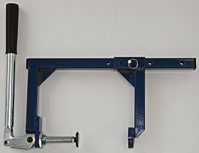
changing valve springs on the car
now most shops will rotate the cylinder to TDC and install an adapter for an air hose and pump a steady 100-130psi into the cylinder to hold the valves closed, but theres frequently clearance problems with headers and the adapters or hose and since you need to wack the valve retainer with a...
garage.grumpysperformance.com
yes I know you want to skip reading links and sub links... its to your benefit to take the time and effort, to read through them
http://garage.grumpysperformance.co...ch-quest-series-similar-350-383-sbc-info.519/
http://garage.grumpysperformance.com/index.php?threads/tbucket-engine-project-dart-shp.3814/
http://garage.grumpysperformance.com/index.php?threads/sellecting-cylinder-heads.796/
http://garage.grumpysperformance.com/index.php?threads/what-to-look-for-in-a-good-engine-combo.9930/
http://garage.grumpysperformance.com/index.php?threads/my-1st-street-383-build.6962/
http://garage.grumpysperformance.co...383-build-that-is-now-going-to-be-a-400.7804/
http://cranecams.com/userfiles/file/334-343.pdf
http://www.woodcarbs.com/valvesprings.htm
http://www.jesel.com/valvetrain/index.p ... rs/tie-bar
https://www.enginebuildermag.com/2010/01/street-performance-cylinder-heads/
https://www.hotrod.com/articles/ccrp-1209-eight-budget-sbc-head-shootout/
http://www.superchevy.com/how-to/engines-drivetrain/sucp-0705-budget-chevy-cylinder-heads/
http://www.superchevy.com/how-to/engines-drivetrain/sucp-0803-performance-cylinder-head-comparison/
http://garage.grumpysperformance.com/index.php?threads/ccing-my-heads.14187/#post-71989
http://garage.grumpysperformance.co...ich-is-best-steel-or-aluminum.3124/#post-9141
http://garage.grumpysperformance.com/index.php?threads/rhodes-lifters.1552/#post-6067
https://sdparts.com/details/scoggin-dic ... ter/sd1005
viewtopic.php?f=52&t=9687&p=48105#p48105
http://www.usaperform.com/documents/Spe ... 0Chart.pdf
Please note, the valve spring pressure figures given here are guidelines only. Some special applications may require different pressures. When in doubt, please contact your camshaft supplier.
ID prefer to use the hardened steel, cup style, valve spring seats, rather than the inner spring diam. style spring seats, if I have the room with the proper machine work of course.
but those are mostly used with single springs , the inner spring diam. seats
are frequently used with dual valve springs and a damper, so you will be using the matched components depending on existing clearances
youll need these also
in an ideal valve train geometry set-up the sweep mark on the valve tip will be very narrow and close to the valve center-line , but having the sweep mark narrow is more important than keeping it centered on the valve stem tip, the valve train does not like lateral or side ways loads on the valves and the wider sweep is an indicator of that issue, while a correctly set up valve train may have components that result in the valve tip sweep mark being slightly off the valve center-line this is not a major concern.
Its checking and verifying the valve train clearances and basic geometry that should be your major concern
check all valve train geometry and clearance on any engine you assemble or modify the valve train on.
the clearances and rocker geometry (push rod length,spring bind rocker to rocker stud clearance, etc.) must be checked carefully prior to starting the engine
http://www.summitracing.com/search/...d-length-checkers?autoview=SKU&ibanner=SREPD5
Proform Pushrod Length Checkers 66789 SBC 3/8" rocker studs
Proform Pushrod Length Checkers 66790 SBC 7/16" rocker studs
Proform Pushrod Length Checkers 66806 BBC 7/16" rocker studs
"THAT PLASTIC THING" is a PUSH ROD LENGTH CHECKER, THE PUSH ROD LENGTH CHECKING, AND ROCKER GEOMETRY TOOL, ARE ENGINE SPECIFIC, so you MUST USE ONE DESIGNED FOR THE SAME STUD DIAM. SPECIFICALLY FOR YOUR SPECIFIC ENGINE, to find the correct rocker geometry and push rod length. If you for example use one designed for 7/16" studs on a SBC and used it on a BBC with 7/16" rocker studs the result would not be close to correct, if the tool designed for one engine is used on the wrong engine, so be damn sure you use the correct tool.
while your rocker wear marks on the valve tips look very close to ideal , you need to verify the push rod length, as getting that rocker geometry correct is important to durability , and a slight change in push rod length may improve that further, keep in mind that having the wear band centered is nice but not as important as keeping in narrow and close to center as possible as a narrow wear band tends to indicate minimal side thrust and as a result minimal wear results
if your seeing a .120-.150 gap between the push rod tip when the "PLASTIC THING" is inserted on the rocker stud ,with the cam lobe /lifter on the base circle AND IF ITS THE CORRECT CHECK TOOL FOR THE APPLICATION,and its resting on the valve tip, your push rods that much too short for the application, your measuring, if the tool rests on the push rod tip and its lets say .060 off the valve tip, that indicated the push rods that much too long for THAT particular application, get within .040 or less on either meassurment and your fine
SOME ROLLER ROCKERS CAN AND DO BIND ON ROCKER STUDS, or rocker adjustment nuts, youll need to check carefully
some roller rocker too retainer combo clearance issues cause problems easily solved with beehive springs and smaller retainer diameters
BEEHIVE SPRINGS GIVE A GOOD DEAL MORE ROCKER TO RETAINER CLEARANCE
https://www.youtube.com/watch?time_continue=93&v=SzD_LZ3fM-s
viewtopic.php?f=52&t=4596&p=18401&hilit=adjustable+guide+plates#p18401
viewtopic.php?f=44&t=2839&p=7344&hilit=adjustable+guide#p7344
If your not getting oil flow, at the rockers,youll still need to verify the oil feed holes line up and are not blocked and the rockers adjusted correctly, try backing off on the adjustment nut as the engine idles to the point the rocker clicks noticeably then slowly tighten just to the point the noise stops , then add only a 1/4 turn, and see if that doesn,t cure the oil feed issue
this is what ERSON CAMS SUGGESTS AND MOST COMPANY'S
HAVE VERY SIMILAR PRESSURE SUGGESTIONS
Id also point out that youll want to lubricate any valve you install in a valve guide and verify the valve train clearances very carefully, and use the correct valve springs and add the correct valve seals installed
roller lifters are generally heavier than flat tappet lifters and roller cams tend to have more aggressive ramp speeds requiring stiffer valve spring load rates
The following recommendations are from Erson Cams. If you have questions, you can reach their tech department at 800-641-7920.
Hydraulic Flat Tappet Camshaft: 110 lbs Seat pressure/250-280 lbs open pressure
Solid Flat Tappet Camshaft: 130 lbs Seat Pressure/300-325 lbs open pressure
Hydraulic Roller Camshaft: 130-140 lbs Seat Pressure/300- 355 lbs open pressure
Solid Roller Camshaft: (Minimum Safe Pressures DEPEND ON SEVERAL FACTORS)
Up to .600Ë valve lift: 200-235 lbs Seat Pressure/600 lbs open pressure
Over .600Ë valve lift: 250-280 lbs Seat pressure /100 lbs pressure for every .100Ë of valve lift
http://garage.grumpysperformance.com/index.php?threads/lifter-weights-and-its-effect-on-rpm.16731/
CAST CAM CORES ARE NOT DESIGNED TO HANDLE OVER ABOUT 130lbs SEAT and 400lbs OPEN SPRING LOADS YOU NEED A BILLET CAM CORE FOR DURABILITY IF THOSE LIMITS ARE EXCEEDED
typically chevy valve springs use single or dual valve springs usually with an inner friction damper
single valve spring with friction damper
dual valve springs with friction damper
dual valve springs without damper
REMEMBER TO CAREFULLY CHECK THE PUSH ROD TOO CYLINDER HEAD GUIDE SLOT AND CYLINDER HEAD CASTING CLEARANCES,IF THE PUSH ROD BINDS IT MAY CAUSE A LOSS OF OIL FLOW THROUGH THE PUSH ROD, FROM LIFTER TOO ROCKER OR THE LIFTER TO WEAR RAPIDLY
checking all valve train clearance issues in mandatory
you must check EVERY ENGINE you assemble,or change valve train components on, for valve spring coil bind, on all springs and dampers,retainer to valve guide clearance,rocker to retained edge clearance, rocker slot to rocker stud clearance,the correct centered rocker to valve tip geometry , piston to valve clearance,push-rod to push-rod guide alignment and clearance , the heads for clearances and a dozen other factors listed below over the whole 720 degree repetitive cycle the valve train cycles thru
obviously you need to verify all valve train clearances and prevent parts binding at any point in the 720 degree repeat cycle the valve train operates in and you need to try to maintain almost all valve train geometry to minimize side loads on valve stems in guides to reduce wear and friction, and keep the lubricant flowing to absorb and remove heat from the valve train components
http://www.gsproducts.com/pac-valve-springs/
http://www.summitracing.com/parts/PRO-66789/
http://www.summitracing.com/search/Part ... -Checkers/
http://www.northernautoparts.com/Produc ... ductId=678
http://www.psisprings.com/index.php?opt ... view&id=17
http://www.cvproducts.com/Products/Engi ... %20Spring/
http://www.gsproducts.com/pac-valve-springs/
WATCH THE VIDEOS, READ THE LINKS
http://www.youtube.com/watch?v=Cqx8Cs6O ... re=related
http://www.youtube.com/watch?v=5GBNLlsi ... re=related
http://garage.grumpysperformance.com/index.php?threads/small-base-circle-cams.3810/
IT WILL HELP A great deal if you,READ THRU THE LINKS AND SUB LINKS
http://www.supercarsunlimited.com/info/ ... prings.htm
http://www.compcams.com/Products/CC-%27 ... %27-0.aspx
http://www.hotrod.com/techarticles/engi ... ewall.html
http://www.summitracing.com/parts/cca-7 ... dia/images
a good set of big block chevy push rods can easily cost over $200-$300
READ THIS THREAD
http://www.hotrod.com/techarticles/engi ... vesprings/
Proper push rod length is absolutely critical for peak performance—minimizing bent or broken valve stems, guide wear, and energy-wasting valve side-loading friction.
With the lifter located on the round base circle, position the Push Rod length Checker (make sure you have the Checker with the proper diameter hole) over the stud. Ideally the Checker should contact the top of the push rod and the valve tip evenly at the same moment, should the Checker contact the push rod first, measure the gap between the front of the checker and the valve tip, and purchase a shorter push rod of the correct length. Should the Checker contact the valve tip first, measure the gap between the back of the Checker and the top of the push rod, and purchase a longer push rod
http://www.summitracing.com/search/...d-length-checkers?autoview=SKU&ibanner=SREPD5
Proform Pushrod Length Checkers 66789 SBC 3/8" rocker studs
Proform Pushrod Length Checkers 66790 SBC 7/16" rocker studs
Proform Pushrod Length Checkers 66806 BBC 7/16" rocker studs
If you suspect a worn cam lobe, checking the cams lobe lift with a dial indicator on the valve spring retainer vs the other lobes would certainly provide useful related info.
knowing vs guessing helps in making decisions wisely
http://www.summitracing.com/parts/pro-66830/overview/
https://www.harborfreight.com/multipositional-magnetic-base-with-fine-adjustment-5645.html
https://www.harborfreight.com/catalogsearch/result/index/?dir=asc&order=EAScore,f,EAFeatured+Weight,f,Sale+Rank,f&q=indicator+stand
http://www.racingsprings.com/
(866) 799-9417
http://www.racingsprings.com/Staff
heres their ph#
Toll Free (866) 799-9417
I always just order the springs retainers valve locks and spring seats as a package deal (NOT CHEAP BUT EVERYTHING WORKS AND FITS) then you just need shims under the valve spring seats occasionally to get the correct installed height
http://www.racingsprings.com/Valve Springs/Store/13
http://store.procompelectronics.com/p-1 ... of-16.aspx
I buy most of the valve springs I use from these guys, if you tell them EXACTLY what you are doing , clearances, cam, spring diam, length etc. they can suggest something that fits your application almost EXACTLY, they are usually very helpful
I usually buy valve springs from these guys
http://www.racingsprings.com/Store/ProductCategory.asp?ProductCategoryID=13
if your not sure what you need in load rates and clearance and installed height,ETC., ask the tech guys on both that site and your cam manufacturers site.
in an ideal world the rocker pushes strait down the valve stem center line to reduce friction,but having the rocker wear pattern centered on the valve tip is far LESS important than having it rather narrow indicating less side thrust or drag on the valve
and having the rocker geometry a bit off as long as the clearances are correct, is unlikely to cause noise issues as much as long term valve guide wear issues
http://www.summitracing.com/parts/CCA-7901-1/
actually measuring clearances helps a great deal
http://www.summitracing.com/parts/PRO-66832/?rtype=10
If your not sure about the proper installed spring height,spring load rates,valve shims ,valve spring seat and required clearances,why not have the machine shop suggest what would match your current needs after telling them the clearance requirements and cam lift.
remember longer valves generally require longer push rods and getting the rocker geometry correct is critical to durability, shims & spring seats can easily be used to shorten installed spring heights,they also make .050 off set valve keepers and .050 off set spring retainers so you can adjust installed height over a full .200 with the same valve length
READ THESE
heres a printable degree wheel
INSTALLED SPRING HEIGHT-MINUS SPRING BIND HEIGHT-minus .060 thousands -EQUALS MAX LIFT
http://www.enginebuildermag.com/Article ... _much.aspx
http://www.kennedysdynotune.com/Valve%2 ... 20Tech.htm
READ THRU THESE INFO LINKS ALSO, THERE A GREAT DEAL OF USEFUL INFO IN THE LINKS, and SUB-LINKS POSTED HERE THAT YOU NEED TO KNOWyes IM sure that appears to be a huge investment in time and effort , but having a durable and stable valve train takes a bit of effort and knowledge to set up correctly, you can rarely just assemble parts and have it work correctly.
If your thinking of running over 450 lbs or valve spring at peak lift Id suggest both 7/16" rocker studs and a stud girdle , be used and if your running 500lbs-600 lbs plus of spring pressure , its pretty much mandatory,on both a sbc and bbc
and Id suggest the STEEL ROLLER ROCKERS,be used rather than aluminum as they have a longer fatigue life, the last thing you want is a rocker stud cracking a head, or a rocker coming apart at high rpms
in theory brass/bronze valve guides are minimally softer and wear faster,than iron valve guides, but in reality if your using the proper valve seals, and have your oil flow to the upper valve train functioning correctly with reasonably clean oil, theres a thin coat of oil between the valve stems and the surface of the inner valve guides, that prevents any wear if your valve train geometry has the main loads centered on the valves center line. keep in mind having proper valve train geometry, and having constant clean oil flowing over and cooling the valve springs, and rockers, plays a huge part in valve wear issues.remember the surface Finnish, clearances, valve seals and oil viscosity along with proper valve train geometry and material used in the valves also effects valve wear
btw coating the valve stems with a mixed slurry of marvel mystery oil and crane cams MOLY assembly lube during the cylinder head assembly process, tends to prevent dry start issues with the guides seizing valve stems
(quote)A valve spring not only has to control the valve train, but also the spring's own weight. So
reducing the weight of the moving end of the spring helps in this matter.
Rick(quote)
heres a chart I found that I don,t fully agree with, I think its a bit conservative, by about 3%-5% on the required cam duration ,required to avoid detonation with todays crappy octane fuel, but it at least gives you a base to work from, but Id suggest selecting a bit more duration
YOUR REALLY GOING TO WANT TO READ THRU THESES SUB LINKS FOR MORE COMPLETE INFO
http://www.compcams.com/technical/FAQ/F ... prings.asp
http://www.pontiacstreetperformance.com ... ngeom.html
http://www.hotrod.com/techarticles/engi ... vesprings/
http://www.carcraft.com/techarticles/vo ... index.html
http://carcraft.automotive.com/9794/vor ... index.html
http://www.supercarsunlimited.com/info/ ... prings.htm
http://www.hi-flow.com/HPYT4.htm
http://www.kmotion.biz/instht.htm
http://www.carcraft.com/techarticles/11 ... index.html
http://www.aa1car.com/library/camshafts.htm
http://www.compcams.com/catalog/COMP201 ... 010_10.pdf
http://www.chevyhiperformance.com/techa ... fters.html
http://garage.grumpysperformance.com/index.php?threads/valve-train-clearances-and-problems.528/
http://www.ovaltracking.com/tech/2006/i ... ive-3.html
http://www.vetteweb.com/tech/vemp_0204_ ... index.html
http://cranecams.com/?show=valveSpringsFAQ
http://www.compcams.com/Products/335-353.PDF
http://www.compperformancegroupstores.c ... re_Code=PH
http://www.cranecams.com/?id=5&show=faq
http://www.popularhotrodding.com/tech/0 ... index.html
http://www.corvetteflorida.com/forums/s ... php?t=5725
http://www.circletrack.com/drivetrainte ... index.html
http://www.circletrack.com/enginetech/c ... index.html
http://www.hotrod.com/howto/51058_cylin ... index.html
http://www.flatlanderracing.com/revkitsafr.html
http://www.powerperformancenews.com/for ... a-863.html
http://popularhotrodding.automotive.com ... index.html
http://www.stockcarracing.com/techartic ... index.html
http://www.supercarsunlimited.com/info/ ... prings.htm
http://www.chevyhiperformance.com/techa ... index.html
http://www.compperformancegroupstores.c ... y_Code=BEE
http://www.popularhotrodding.com/engine ... ables.html
If your rebuilding an engine ,the questions that really should be asked here......
were you completely happy with the old cam or did you feel you wanted more upper or lower rpm band torque, did you like the way the engine ran, or did you feel it needed some tweaking?.....
what would you have liked to be changed about the power band when the old grind was in use?
BTW are you aware that reducing cams lift and valve spring load rates /pressures, and the degree of the aggressive cam ramp acceleration tends to increase durability in valve train components? yes it may cost you some hp, but it may be a good trade for increased durability
thats something thats partly an art, not truly an exact science, due to differences in ramp acceleration rates, lifter design, and valve train geometry, spring load rates,harmonics, etc. I usually contact the cam manufacturer and get their input,, because they are very much interested in having their product perform well. then I carefully verify my combos clearances and spring load rates,(verifying the clearance issues are VERY important) but you need to understand that if you substitute a different brand or style of lifter or rocker,etc. its going to change the results, harmonics and rpm band, generally you can add some stability with a rocker stud girdle, and if you find your having control issues you can usually either add a rev kit or swap to a slightly stronger load rate in a beehive or dual spring.
you might want to look into BEE HIVE VALVE SPRINGS, because, if they are available for your application. they allow both a lighter spring with the same pressures and a smaller diam, and lighter weight retainer , giving greater rocker clearance and lighter inertial loads at high rpm
lower spring pressures usually result in less wear on the valve train, smaller diam. retainers, used on bee hive springs generally allows higher rpms and lower loads on the valve train, IDEALLY, you want the LOWEST spring rates and LIGHTEST valve train components that will still control the valve train in the rpm ranges your engine operates in.
check with your cam supplier they tend to cost slightly more but they can give you some additional rpm capacity and lower stress
keep in mind the seat diam. on the heads is usually limited or set by what can be machined ,the coil bind or stack height and installed height must match the cam lift clearance and and both the open and stationary s, issues like inside dia. and distances between retainer and valve guides ETC. dictate the valve seals that can be used, spring loads must match the application, yes
when you select a cam, the cam supplier will generally suggest matched springs, and an installed height and matched components, and yes they have a marked interest in your engine performing well , so they will tend to give good info, they are NOT just trying in most cases ,to increase their profits by selling you stuff you don,t need.
yes stock springs are fine IN SOME APPLICATIONS, but you must ALWAYS check spring clearances and loads and valve train geometry
theres a big difference in spring quality between the O.E.M and the better aftermarket springs and running double or triple springs can at times be an option, remember lighter valve train components usually reduce stress, allow less spring pressure and resulting valve train wear, and tend to increase the rpm range.
btw your generally fighting a hopeless battle if your expecting complete valve control with any hydraulic cam design much over about 6400rpm-6500rpm
and your valve spring load rates do effect the roller lifters life expectancy, high load rates decrease the cams life span and increase wear issues
Smokey Yunick discovered that valve springs raise the operating temperature of engine oil more than combustion heat with his own version of today's "Spintron" spin fixture. From the Circle Track Archives
keep in mind that you can use EITHER self aligning rockers OR guide plates BUT NOT BOTH at the SAME TIME with properly installed screw in rocker studs
http://www.racingsprings.com/
http://www.iskycams.com/psisprings.php
http://www.psisprings.com/index.php?opt ... view&id=17
http://www.ovaltracking.com/tech/2006/i ... ive-3.html
self aligning rockers have ridges to prevent the rocker from moving off the valve stem
left is a BEEHIVE SPRING,with small light weight retainer, RIGHT SIDE STANDARD SPRING standard retainer
http://www.dougherbert.com/1445beehives ... 22853.html
http://www.jegs.com/webapp/wcs/stores/s ... 7_-1_10699
http://www.carcraft.com/techarticles/vo ... g_upgrade/
Id use any decent quality springs from any NAME BRAND manufacturer regardless of brand if the clearance and load rate specs matched the required clearances and loads, naturally the manufacturer of the cam has a vested interest in your engine running correctly so their advice should be taken seriously, but because its a very competitive market they will rarely point out the BEST springs, opting for the slightly more that adequate choice to keep the costs lower and make the sale, knowing that in most cases that's going to be the best compromise , but I certainly would avoid "deals" from sources like EBAY where your not sure what your getting and they have little to loose selling cheap imported junk, after all its YOUR engine that's going to be damaged if they fail, and quality COSTS more than JUNK!
as a general guide flat tappet cams , and mild hydraulic roller cams will want about a 120 lb seat and 330-340 lb over the nose full open spring load rates
its not until you get into the solid roller cams that the load rates jump significantly
naturally you'll want to read the cam manufactures info on clearances, posted on the cam cards and their web sights , as to suggested installed height, spring diam. and load rates before selecting springs or setting up your clearances and the installed heights and spring bind heights do vary a good deal, and don,t forget to verify the valve train clearances and geometry, as a general rule, sbc hydraulic cams used with stock heads,will work with lifts of 0.475 and under, and work with most stock springs
yes we all know guys who (SUCCESSFULLY??) installed a .500 lift cam with good result (SO FAR), but without checking clearances carefully that also a great way to have problems, and its that not checking that results in most of the problems I constantly see, as a result of cam swaps, youll also want to keep in mind that the DURATION and LSA (LOBE SEPARATION ANGLE) play a part in the clearance issues, between the valves and pistons
obviously getting the clearances wrong, or over reveing the engine can cause problems
http://www.summitracing.com/parts/pro-66830
http://www.centuryperformance.com/check ... g-144.html
http://www.racingheadservice.com/Inform ... arance.asp
http://www.cdxglobal.com/content/sample ... ear_WS.pdf
http://www.chevyhiperformance.com/techa ... index.html
http://www.carcraft.com/howto/116_0701_ ... index.html
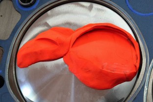
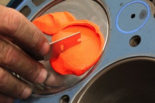
ISKY CAMS SELLS CUTTERS LIKE THIS TO NOTCH PISTONS
there's hundreds of ways to destroy an engine, but a common route is trying to compress solid objects in the combustion chamber where there's not nearly enough clearance, or having the valve train bind up due to clearance issues or reeving the engine above its valve control limitations. lack of lubrication and too much heat can easily be factors but...
failure to keep the pistons from hitting the valves, bending valves, ,over reeving the valve train and having un-controlled valve movement, or having chunks of piston ,that detonation can break loose, being compressed against the heads can result in the cracked cylinders, and bent rods like the pictures below show
any part can fail but running valve springs up near their minimum clearance and maximum rpm range limitations is just asking for problems
Last edited by a moderator:


 Print
Print  Email
Email