great question!
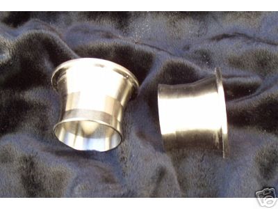
obviously if your building your own custom intake youve got the option of fabricating a mini plenum between the two intake runners and the venturies of the weber carb as one option,but just building the runner larger than the carb venturie exit dia. should help some as the abrupt reduction in runner cross section should help on reducing reversion,
Its been my experiance that the cones or anti reversion baffles help,
on both intake runners and header exhaust primairies, but fighting the symtom vs correcting the cause might be less effective.yes they work,mostly because they tend to break-up the smooth reverse flow out of the intake runners, but restict the intake runner to a cross sectional area, of equal or less than the carbs venturie cross sectional area and you may be restricting your potential power in the upper rpm range to cure a low rpm problem.
keep in mind theres both intake runner reversion caused by the intake valve remaining open longer in performance cam designs ,so as to allow good high rpm cylinder scavaging ,where the mass of fast moving ,exiting exhausts inertia, and the resulting low pressure way it tends to cause, helps drag in the next intake charge which helps make better high rpm power , but that same overlaps in the valve timing has
the unwanted results that as the piston starts compressing the cylinder volume at low rpms ,the intake runners charge inertia in the runners is reversed and reversion can result it can also occure due to residual exhaust pressure in a few cases. stroke, cpr,and both intake and exhaust design and cam timing naturally influeance the degree of reversion, in some cases reconfiguring your exhaust tunning or header config,or retarding your cam timing makes a noticable differance in the amount of reversion youll see, in some cases.
naturally tighter LSA like 104-110-in the cam sellected at any durration, range vs a wide LSA, like 112-116 and longer exhaust durration than the intake durration,in the cam timing tends to add to the problem.
HERES WHAT ISKY CAMS SAYS
What Causes Intake Reversion? Once and for all, let us have the TRUTH!
With the proliferation of the Motorsports Industry over the years, many new faces have come on the scene. In the cam grinding business today, there are many younger, less experienced companies struggling for recognition of their talents and a few have turned to postulating new theories in order to attract attention. However, they are I believe unfortunately, too often guilty of shooting from the hip.
Two in particular are responsible for perpetuating the "myth" that an earlier opening of the intake valve (even by a mere 2 or 3 degrees) causes the phenomenon known as "reversion". Nothing could be further from the truth! This misconception not only defies common sense, it also establishes a false premise from which other, incorrect conclusions can be drawn. Simply put, those who focus on overlap are on the wrong end of the cam-timing diagram!
http://www.jegs.com/p/Magnafuel/1119292/10002/-1
Reversion, carburetor/Injector "stand-off" or the general effect of the backing up of the intake Fuel/Air charge normally associated with longer duration high-performance camshafts is actually caused by a Later Intake Closing! How do we know this to be true? The answer lies in the basic principles of physics. For as with geometry and trigonometry, these sacred truths do not change simply because someone chooses to ignore them in an attempt to garner a reputation.
Specifically, when the intake valve opens some 40 or more degrees before T.D.C. at the end of the exhaust stroke, very little (virtually no) exhaust gases remain in the cylinder. The piston is in the vicinity of T.D.C. (only .425" down the hole @40o BTDC - on a typical 350" Chevy with 5.700" rods) and no appreciable threat is posed to the forthcoming intake charge. The "False Reversion Hypothesis" taken to an extreme would lead one to the equally false conclusion that any overlapping of the intake and exhaust valves is totally undesirable. Automotive engineers of the late 1800's and early 1900's used to think this way. They were deathly afraid of overlap, so much so they actually employed "Negative" overlap (minus 5 or 10 degrees) to be absolutely sure none would occur. What was the result? These engines were severely "throttled back" or limited to low speeds and mediocre output. [ Reference: Iskenderian's Tech Article "Cam Degreeing is Simple"] But, more progressive engineers of the early 1920's who performed "brazen experiments" with longer duration cams proved these overlap fears to be only so much "stuff and nonsense", as both power, rpm and performance were actually improved. These engineers demonstrated that overlap did not cause engines to quiver, backfire or lock-up on the spot! Although, the ignorance displayed by their predecessors is easily explained by their lack of experience, (internal combustion engine design being in it's infancy) it was none the less the result of an incorrect hypothesis.
Should you need further persuasion that reversion is not caused by earlier intake opening and the resulting extension of valve overlap, consider this: What happens when you advance any camshaft? The intake as well as the exhaust valves open earlier. Does this advancing of the cam cause more reversion? Of course not. Throttle response and torque are enhanced. Yet, if these theories were correct wouldn't the engine run more poorly, especially at lower RPM? The answer is obviously yes, and because so, these theories are invalid. A brief look at what's happening on the other end of the valve-timing diagram will tell you why.
For when a camshaft is advanced, not only do both valves open earlier but they of course also close earlier - and here in lies the key to reducing Intake Reversion. Close your intake valves earlier and any tendency for the occurrence of Reversion or the backing up of the intake charge as the piston rises on the compression stroke will be reduced. It's not complex, nor is it a mystery. And the circumstances surrounding it's occurrence have not changed. In fact any experienced mechanic could tell you as much, for, as Ed's good friend the legendary Smokey Yunick might say, "Only country smarts are required to solve the problem."
FROM ISKY AGAIN....
Longer Exhaust Duration: Is this really necessary?
Most stock camshafts from American production V8, V6 and 4 cylinder engines manufactured today are ground with the longer exhaust lobe duration. Or, another way of looking at this is that they are ground with shorter intake durations! The former embraces the viewpoint that either the Exhaust Ports or Exhaust Pipe system is somewhat restrictive, and is in need of an assist. The latter suggests that the intake system is rather efficient and cam timing can be trimmed back a bit with out much sacrifice in power, in order to maximize throttle response and cruising efficiency.
Take your pick here. There is no absolutely correct viewpoint - because both are probably true! In a stock engine running at conservative RPM levels, for the sake of overall efficiency, fuel economy and a quiet smooth running engine, this staggering of intake and exhaust duration is quite common and appropriate.
However, High Performance is another thing entirely. Change one factor, let's say in this case, the exhaust system (installing headers and larger pipes) and you have just negated in most cases, the need for that longer exhaust lobe. Now couple this change with a different intake system and camshaft and you have really scrambled the equation. But, wait just a moment. Why is it that so many people (racers & cam grinders alike) insist on running a cam with longer exhaust duration regardless of what equipment is employed? The answer is "habit". Most of them have been somewhat successful in doing it their way and will probably never change unless virtually forced by circumstances to do so.
Before we go any further however let's review what it actually is we are trying to do with an engine when we attempt to make more power. Our best result comes when we are cognizant of the fact that an engine is basically an air pump. We pump it in and out (although in a different form) and we have problems when one side or the other is restricted. Balance or the equilibrium or flow should be our objective, unless of course we are not trying to make more horsepower!
Example #1 (Oval track racing) Here, I have often observed that the most experienced drivers are those who are most likely to run a single pattern (equal on intake and exhaust duration) cam. Why? Because such cams always, I repeat always make more torque! These veterans have a more educated foot and greater experience in feathering the throttle in the corners. They can therefore, utilize the benefit of added torque, in the lower to mid RPM range, to their advantage.
Their counterparts, the younger drivers on the circuit, generally are not as experienced and may at times actually get "crossed up" in the corners especially with a lighter car or when they are learning the ropes. In their case, a longer exhaust duration is often the more appropriate choice. It will often help them to drive better, more "flat footed" if you will, without consequence. But please for the sake of accuracy, let us be truthful. The benefit comes from an actual bleeding off of low to mid range torque, which is always what happens when Exh. Duration is lengthened, not from any improvement. The improvement, (if any) would come because of an improvement in scavenging at the extreme upper end of the power curve and would usually be marginal at best. Yet the so-called "extra power" potential of a longer Exh. Duration cam is most often why they are touted - power most people are backing away from at the end of the strait away!
Example #2 (Drag Racing) At the drag strip it's a little different and I feel more honest. Here, racers have long enjoyed longer exhaust and longer durations across the board (If I may add specifically for the purpose of "killing" low-end torque) to keep the tires from too easily breaking lose. This has been successful and sometimes actually results in a slight increase in top end power - something you can actually use in drag racing since it is a full throttle endeavor through the lights. Keep in mind here though, it's quite possible that a longer duration cam overall would have done just as well or better. In other words if you needed that longer exhaust for top end, perhaps the intake could have benefited from such a lengthening as well.
One of my favorite expressions is how "The Drag Racing mentality has infiltrated the ranks of Oval Track". Many have crossed over and made the switch in the past 10-15 years and some have brought their preconceived notions about how to cam an engine with them. A few may actually read these concepts and if they do so will at least come away with a better understanding of what they are doing. On the other hand they also could find that this information might actually help their cars to run just a bit faster! "


 Thanks, Grumpy! That helps put this into perspective for me. I want to get it right, so I am taking a step back and will be doing some research priour to the final design of my IR intake. Many years ago, I read several chapters in a library reference volume of Sir Harry Ricardo's two-volume work entitled "The Internal Combustion Engineâ€, published in 1923......