as most of the older long time readers of this forum, might know ,I build mostly big block chevy, pontiac, DODGE big blocks and a few small block chevy and older hemi engines and over the years Ive long ago lost count of the guys Ive built engines for that SHREDDED 10 bolt rear differentials, now don,t get me wrong as long as you run street tires and don,t engage in stupid stuff like 4500rpm standing start launches a 10 bolt differential will stand a surprising amount of abuse, but add slicks, on a heavy car (3400 lbs plus)and engage in jack rabbit starts and that 10 bolt rear differentials on very limited time!
build a high performance 454-540 BIG BLOCK chevy or a 421-467 PONTIAC and add slicks, good traction, and you've quickly found a well know recipe for a shredded rear differential and busted u-joints.
I almost universally suggest anyone thinking of racing a car with decent tires strongly consider up-grading any 10 bolt G.M. differential to at least a 12 bolt, or better yet a ford 9", dana 60, 9.3" pontiac differential, or at least a 9.25" mopar differential. you only have too puke axles, loose a wheel, and shred ring gears a few times to have that bit of experience,brought home so you don,t forget it!
and keep in mind it doesn,t take a killer bbc to do that, IVE done it with serious 396-402 BBC engines
think of a well built big block or nitrous assisted small block that can easily exceed 550-600 ft lbs of torque, them throw that thru a 3.73:1-4.11:1 rear gear and having WELL over a ton of force on a rear axle is not only normal its easily exceeded, and add shock loads and you could triple the impact load on the gear teeth and axles very easily
I FOUND THIS INFO RECENTLY ON THE INTERNET ( posted by "The Master")
These rear ends can hold up to 350-400HP as long as you DO NOT run slicks on them. There is some part numbers to help you get started. The biggest flaw with the 10-bolt design is the flexibility of the case. When under heavy load, the pinion walks up the ring gear face, and forces the case apart. This totally throws off the gear alignment which causes premature gear failure. One reason is due to the poorly designed crush sleeve by GM. Both of these can cause you to take teeth off of the ring and pinion gears. In order to build a sturdy 7.5 or 7.625 rearend that can take some abuse you need to start with A good set of gears. Do NOT buy a cheap set of gears, stick with quality set of GM, Richmond, US Gear, or Strange gears. Secondly buy a good posi unit like SLP, Auburn or Eaton. If you can try to stay away from spools since they put excessive strain on the axle ends and can break them. Weld the axles tubs all the way around the housing. GM only uses two small spot welds on each tube to hold them to the housing. This causes the tubes to flex under load. Welding them will help stop this. When you install your pinion gear throw away the cheap crush sleeve and buy a solid pinion support like the one from Ratech. After you have your pinion bolted up install your posi unit/gears and try to keep the gear mesh as tight as possible without running into problem like excessive gear noise. After thats done dont forget to finish it up with a nice strong support cover like the one from Summit or TA performance. A strong cover like these will help strengthen the case. A few more things to remember is that you can add a Zytanium cross pin. It is available in the year one next generation catalog. The stockers have a tendency to shear off. Dont forget to fill it back up with a good shockproof gear oil from redline or mobil 1. IF you follow this you can build a decently strong 10 bolt rearend. Remeber you need (1.) A good gear set (2.) a good posi unit (3.) pinion spacer instead of cruch sleeve (4.) good support cover (5.) weld axle tubes. The if you want you can add the Zytanium pin. I would not worry about breaking the stock axles, they are pretty strong. If you are worried you can buy a set of Moser's for around $300
P.S. I WROTE THIS FOR YOUR PERSONAL USE ONLY. I AM NOT LIABLE FOR ANYTHING THAT MAY HAPPEN TO YOUR REAREND. THIS IS MY PERSONNAL OPINION OF STRENGTHING A 10 BOLT WITH A BUDGET IN MIND. USE AT YOUR OWN RISK!
------
http://www.Summitracing.com
MSR-9000 (Moser) Chevrolet: 10/12-bolt, 1.533 in. seat, C-clip eliminator kit
MSR-9100 (Moser) Chevrolet: 10/12-bolt, large bearing, 1.533 seat, C-clip eliminator kit
MSR-9200 (Moser) Chevrolet: 10/12-bolt, 1.400 in. seat, for stock axles, C-clip eliminator kit
RAT-108K (Ratech)GM: 1977-96 10-bolt, 7.5 in. and 7.625 in. ring gear, installation kit
RAT-3001K (Ratech)GM: 1980-up 10-bolt, 7.5 in. and 7.625 in. ring gear, deluxe installation kit
RAT-4111 (Ratech) GM: 10-bolt, 7.5 in., 8.2 in., differential, solid pinion bearing spacer with shim pack (Personal sidenote..This takes place of the origonal crushsleeve and helps stop the pinion from walking up the ring gear by giving it more support)
RMG-8310441 (Richmond)GM: 1982 to present, 10-bolt, 7.5 or 7.625 in., ring and pinion
installation kit
SME-8510400 (Summit)GM: 7.5 in., 10 bolt rear-end aluminum support cover
CNF-6086P (Con Ferr)Differential Cover, Aluminum, Polished, GM, 7 1/2 inch, 10-Bolt, Kit
ETN-19599-010 (Eaton)Differential, Posi Performance, Limited Slip, 28-Spline, GM/Honda/Izuzu, 7 5/8 in
ETN-19663-010 (Eaton)Differential, Posi Performance, Limited Slip, 26-Spline, GM, 7 1/2 in
-------
http://www.Jegs.Com
109-542040 (Auburn)88-Up, 3.23-Up GM 7-1/2'' & 7-5/8'' 10-Bolt, 28-Spline
109-542041 (auburn)88-Up, 3.08-Down GM 7-1/2'' & 7-5/8'' 10-Bolt, 28-Spline
Before you attempt doing this yourself, you need to read and decide if you are equipped, capable and willing. If not, you’ll save time, sweat and heartache if you pay a competent rear end professional to handle it. On the other hand, doing it yourself is the only way to really learn how.
Much of this information is applicable to differentials in general, but most is specific to the installation of the Zexel-Torsen limited slip carrier into GM 7.5†or 7.625†rear differentials with 3.23 or numerically higher gears and 28 spline axles. Most ’89 and up GM models have 28 spline axles. However GM did use a few leftover 26 spline axles after ’89, mostly in 2.2s and 2.8s. If your vehicle is near the ’89 changeover date check to be sure. If you have 26 spline axles you can purchase a set of 28 spline axles and still do the install.
Ok, are you ready to get sweat, greasy and possibly frustrated while installing your Zexel limited slip carrier, AKA Posi-Traction?
If so, loosen the 13mm-1/2†cover bolts and drain the gear oil into a suitable container. Jack or lift the rear end after loosening the rear wheel lug nuts. Securely support the vehicle as high as you can on appropriate jack stands. Remove the rear wheels. Remove the brake drums by tapping firmly around the rear edge while pulling outward.
Remove the differential cover and rotate the carrier until you have access to remove the 10mm-5/16†pinion shaft retaining bolt (use a 6 point socket to avoid rounding it off). You can now remove the pinion shaft that slides between the ends of the axles and keeps them from moving inward. Gently push one axle in to remove the large C-clip that secures the axle from moving outward. Carefully slide the axle out of the axle tube so as not to damage the outer axle bearing. Use a clean rag to wipe excess oil off as you withdraw it. Push in the other axle to remove it’s C-clip and carefully slide it out.
Since you have the axles out, go ahead and replace the axle oil seals located at the end of each axle tube. These seals are inexpensive and may start leaking as mileage increases. It’s easier to pull the seals out with a seal removal tool, but you can use the tip end of the axle. Be careful not to damage the bearings or sealing surfaces on the ends of the axle tubes. You’ll get a bit more differential fluid draining out of the axle tubes when you remove these seals. Be sure to collect it in your drain pan. If you have high mileage you should consider replacing the axle bearings also. You’ll need a slide hammer and a bearing removal tool that is able to pull from behind the seal. You may need to obtain the axle housing code to get the correct P/N seals and bearings. The axle housing code is stamped on the front of the passenger side axle tube, between the pumpkin and brake backing plate. Insert new seals and fully seat them by pounding them in flush with a large socket.
Ok! Back to the carrier removal. On each side of the carrier there is a main end cap secured over the carrier bearing races by two 16mm bolts. Mark the caps so they can be returned to their original location. Remove and set aside the four bolts and end caps. The carrier can now be removed from the differential housing, but first examine either end of the carrier and you will see shims wedged between the bearing races and differential housing. They are used to pre-load the carrier bearings and adjust the position of the ring gear for proper backlash.
Keep an eye on the shims when you pull the carrier out so you’ll be able to relocate them in their original locations. You will use these shims or new ones close to the same thickness as a starting point for proper backlash adjustment. If your rear end is in reasonably good shape, and you are just swapping in the Zexel carrier and using your old gears, you may get lucky and backlash will remain within the specification limits of .006†- .010â€, but don’t count on it. That’s why you bought an install kit complete with varying thickness shims.
You’ll need a pry bar or bars and block of wood to coax the carrier out of the differential housing. You can use the 3lb. dead blow hammer or sledge to bang the carrier housing while you pry to get it started. Be careful not to damage the gasket-sealing surface of the differential housing or the ring gear. The bearing races, tapered metal rings that cover the carrier bearings, may fall off as the carrier comes out. They set over the bearings on either end of the carrier and are held in place when the carrier is installed and shimmed. You’re going to replace both of these inexpensive bearing races with new ones. Consider it cheap insurance to protect the like new bearings which are already pressed into both ends of the Zexel unit.
To transfer the ring gear YOU WILL NEED TO USE A BENCH VICE to hold it while you remove the 19mm-3/4" bolts that secure it to the OEM carrier. (*IMPORTANT NOTE: THESE BOLTS ARE REVERSE THREAD.) Cushion the carrier with a thick towel while mounting in the vice. If you haven’t removed the rectangular pinion block from the middle of the Zexel unit, do so now. This metal slab will slide in between the ends of the axles to keep them pushed out the same way the large cylindrical pinion shaft in the old carrier did. (NOTE: If you are running larger than 3.42 ring and pinion gears you may have to machine or file a couple grooves in the pinion block to slide it past the ring gear teeth later in the install procedure). Be sure to clean the ring gear and all bolts before installing it on the Zexel carrier. If the bolts are in good condition you can reuse them or use new high quality bolts. The old OEM bolts are better than cheap after market ones. Mount the Zexel into the vice and transfer the ring gear. Install the REVERSE THREAD 19mm bolts using Locktite and torque to 90ft.lbs. Torque the bolts in a couple stages while moving across and around the ring gear in a star pattern.
Now with the carrier out it’s time to thoroughly clean the differential housing. Remove gasket material from the sealing surface and wash out the housing with clean solvent. Check all of the oil passages and grooves to make certain that there are no metal particles or dirt remaining.
You’re now ready to install the Zexel carrier into the clean differential housing. Apply clean gear oil to both carrier bearings. You don’t need to pack them with grease. Position the carrier with the new bearing races in place and shim the left side first. While holding the assembly in place shim the right side (an assistant will make it easier).
Clean and re-install the two carrier end caps in their original location over the bearing races. Torque the 16mm bolts to 50-60ft.lbs. Use Locktite on all bolts in final assembly.
Now carefully slide the axles back in taking care not to damage the lips of the seal and insert the C-clip into the retaining groove. Pull the axle back out to seat the C-clip in the counter-bore of the side gear. Clean and insert the rectangular pinion block between the ends of the axles. Tap it in lightly to seat it, don’t force it. If it resist insertion pull the axles outward while rotating slightly back and forth to be sure they are seated correctly. Locktite and torque the retaining bolt. Rotate the drive shaft to make sure everything is meshed correctly and the assembly rotates smoothly.
Apply a thin bead of gasket sealing compound around the cover and position the gasket onto it. Install the cover with gasket and torque the 13mm bolts to 10-15ft.lbs, again moving in a side to side sequence around the cover. Fill the differential with fresh gear oil to the bottom of the fill hole. Check for any leaks around the differential. Re-mount the brake drums and wheels, lower the vehicle and go for a test drive. Check the differential fluid level again on level ground after your test drive since some of the gear oil may have flowed back into the axle tubes. Congratulations, you now have two legs!
how to check and adjust for proper setup:
Here is some basic differential terminology you should learn.
Flank – the bottom area of the ring gear that the gear teeth rise from. Also called the root
Face – the top flat surface of each gear tooth also called the top land
Drive – the convex side of the ring gear teeth which the pinion contacts to drive the ring gear
Coast – the concave side of the ring gear teeth opposite the drive, also contacted by pinion gear
Heel – the outer edge of the ring gear
Toe – the inner edge of the ring gear
Pinion depth – the position at which the pinion contacts the ring gear teeth between the face and flank
Pattern – the “footprint†where the pinion gear contacts the drive and coast sides of the ring gear teeth (viewed by use of gear marking compound)
Backlash – the amount of free movement of the ring gear with the pinion held fixed in place
Pre-load – the initial amount of force applied to the races upon the bearings
When working on a differential there are four basic adjustments. In order of importance they are:
1. Pinion Depth
2. Pinion Bearing Pre-load
3. Backlash
4. Carrier Bearing Pre-load
Be aware that adjustments of pinion depth, pre-load and backlash effect each other. When you change one you must re-check the others. Therefore it’s important to understand that for a correct install you may have to remove the carrier several times to make the necessary adjustments, indicated by the pattern and backlash measurements, to achieve proper alignment.
Before you can adjust pinion dept you must set backlash. The best way to obtain backlash reading is with a dial indicator. You should be able to get a close indication of initial pinion depth if the backlash is within, or very close to the .006†- .010†specification. On most ring and pinion sets backlash will change about 0.007†for each 0.010†that the carrier is moved. Therefore if you need to decrease the backlash by 0.007â€, move the carrier 0.010†closer to the pinion by shimming the left side. If you need to increase the backlash by 0.007â€, move the carrier 0.010†farther away from the pinion by shimming the right side. Use a pencil and paper to keep notes of shim combinations and backlash. A calculator might also come in handy.
After setting the backlash you can check pinion depth. Do this by brushing three or four of the ring gear teeth with a moderate coat of compound in two locations on the ring gear. Rotate the ring gear past the pinion gear four or five times to print a good pattern. The gear marking compound will show a clear pattern of pinion contact on the ring.
The pattern you’re looking to achieve should be oval in shape and centered between the face and flank on the drive and coast side of the ring gear teeth. There should be an area of no contact below the face and above the heel on both sides. It would be ideal if the pattern was also centered between the heel and toe of the ring gear, but that is not necessary. The only part of the pattern that helps set the pinion depth correctly is the contact position between the face and flank of the teeth, regardless of the location concerning heel and toe. I’ll say it again; if the contact pattern is towards the heel or the toe of the ring gear teeth ignore that and look only at the position from face to flank. In most cases an ideal heel to toe pattern can not be achieved anyway. Trying to make adjustments to get a pattern that is centered from heel to toe will usually lead to frustration and a noisy gear set. The position of the pinion bearing bore in the housing and housing alignment affects the pattern from heel to toe and can not be corrected without machine work. So once again, a contact pattern that is centered from face to flank on the drive and coast side always indicates correct pinion depth even if the pattern can’t be centered from heel to toe.
If the contact pattern is towards the face of the ring gear teeth then the pinion is too far away from the ring gear. To correct it the pinion needs to be moved towards the ring gear with a thicker shim to position it closer to the ring gear centerline. If the contact pattern is towards the flank of the ring gear teeth then the pinion is too close to the ring gear. To correct it the pinion needs to be moved away from the ring gear centerline with a thinner shim. The shim is located between the gear and rear bearing.
If the backlash is within spec but the pinion depth is not correct you match-mark the driveshaft to the pinion flange and remove the driveshaft and suspend it with wire out of the way on something like the exhaust pipe. Match-mark the pinion flange, pinion shaft and nut (if you’re reusing the nut). Now check the bearing pre-load using an inch-pound torque wrench and record it before disassembly. The pre-load is the torque required to just begin turning the pinion shaft.
To remove the pinion nut and washer you will need to use a special flange holding tool or breaker bar to hold the flange in place while you loosen the nut. You may also want to install the cover loosely with a couple bolts so the pinion doesn't fall out. With the nut and washer off use a two-jaw puller to withdraw the flange by placing the two jaws on the backside of the flange and the puller screw on the pinion. Examine the sealing surfaces of the flange for nicks or gouges. Replace the flange if it's damaged. Use a blunt chisel to remove the pinion oil seal, being careful not to damage the carrier housing. The pinion can now be removed from inside the carrier case to replace the bearings, races, correct thickness shim and crush sleeve. It’s easiest to assemble the pinion without a crush sleeve until the correct pinion depth has been established. Install the new pinion oil seal. When initially installing the pinion slowly tighten the pinion nut until the pre-load is within the assembly specifications of 12-15 in. lbs. on a new pinion gear and 6-7 in. lbs. on a used pinion.
Understand this is the hard way to set pinion depth without the six or seven special jigs, and guage a GM tech has available. They can simple install the various jigs and get a reading on the guage that translates into the correct thickness shim required.
When changing the pinion depth always make large changes until the pattern is close. Consider 0.005†to 0.015†to be a large change and 0.002†to 0.004†to be a small change. Changes of 0.005†to 0.008†or more will lead to the correct pattern faster than small changes will. If you move the pinion too far and the pattern changes from one extreme to the other then you know that the correct pattern is somewhere between the two extremes. Once you get close to the correct pinion depth make smaller changes until the pattern is centered between the face and the flank of the ring gear teeth. After the backlash and pinion depth are set remove the carrier and set the final pinion bearing pre-load of 12-15 in. lbs. on new pinion gear and 6-7 in. lbs. on a used pinion. Use a new crush sleeve for final assembly. Use oil on the pinion nut washer surface during all assemblies and red Loctite on the pinion nut threads during the final assembly. The oil on the washer surface helps the nut turn easier while it is being tightened and the red Loctite helps keep it tight.
On a crush sleeve design differential it usually takes between 300 and 400 foot pounds of torque to crush the crush sleeve. Use a large breaker bar and or very strong air operated impact wrenches to crush the crush sleeve. Proceed very slowly so that you get it right the first time. The pinion preload will be zero until the bearings contact the races. When the bearings contact the races the preload will increase very quickly. Take plenty of time to set the preload carefully so that the bearings will have a long life. If the crush sleeve is over crushed and the pinion bearing preload exceeds the specified allowable range the only solution that I know of is to install another new crush sleeve and start over. After reaching the correct pre-load, moderately tap both ends of the pinion to seat the bearings, races and yoke. Be careful not to hit the pinion so hard that it damages the bearings. After “seating†the pinion check the pre-load again to make certain that it is correct.
After setting the pinion depth, backlash, and pinion bearing pre-load it’s time to set the carrier bearing pre-load. During the original set-up you set the backlash with very little carrier bearing pre-load. Now set correct pre-load by inserting equal thickness shims to each side. Make it fairly tight, as tight as you can without damaging the shims while driving them in. If the pre-load is close and the backlash is wide, add shims to the left side. This increases the carrier bearing pre-load and decreases the backlash at the same time. If the pre-load is close and the backlash is too tight, add shims to the right side. This increases both the carrier bearing pre-oad and the backlash at the same time.
Now that the pinion depth, pinion bearing preload, backlash, and carrier bearing preload are set recheck the pattern once more to be certain that everything is perfect before final assembly.
All new gear sets require a break-in period to prevent damage from overheating. After driving the first 15 or 20 miles it is best to let the differential cool before proceeding. 500 miles are recommended before towing. Tow for very short distances (less than 15 miles) and letting the differential cool before continuing during the first 45 towing miles. This may seem unnecessary but many differentials are damaged from being loaded before the gear set was broken-in. It's also recommended to change the gear oil after the first 500 miles. This will remove any metal particles or phosphorus coating that has come from the new gear set.
Knowing how much torque you are applying (this assumes you have perfect traction with only a 10% slippage at your slick) to the axel here is a chart of aftermarket axels listing their failure points (on average).
28 spline axel________1.200" dia. ________ 4,571 lbs.-ft. stock (GM test data)
28 spline axel stub ___1.250" dia. ________ 3,787 lbs.-ft. stock Corvette (Dana 44)
30 spline axel________1.250" dia. ________ 6,473 lbs.-ft. stock (GM test data)
31 spline axel________1.315" dia. ________ 7,000 lbs.-ft. (Ford 8.8" rear)
33 spline axel________1.370" dia. ________ 8,200 lbs.-ft. (GM 14 bolt truck)
35 spline axel________1.500" dia. _______ 9,600 lbs.-ft. (Dana 60)
40 spline axel________1.710" dia. _______ 12,000 lbs.-ft.
Here is a web site with a great graphic that shows why spline count is so important.
http://performanceunlimited.com/documen ... guide.html
http://www.jegs.com/p/LPW/LPW-Ultimate- ... 5/10002/-1
AS USUAL THERES A TON OF INFO IN THE LINKS
http://www.highperformancepontiac.com/t ... ewall.html
http://coloradok5.com/axleguide.shtml
viewtopic.php?f=45&t=273&p=11774&hilit=axle+strength#p11774
http://www.drivetrain.com/parts_catalog ... nions.html
http://www.chevyhiperformance.com/techa ... index.html
http://www.carcraft.com/techarticles/cc ... index.html
http://www.markwilliams.com/gm10bolt.as ... goryID=183
http://www.superchevy.com/technical/eng ... ewall.html
http://www.ws6transam.org/10bolt.html
http://www.maliburacing.com/tech_rearend_swaps.html
http://www.maliburacing.com/ford_9_inch ... e_inch.htm
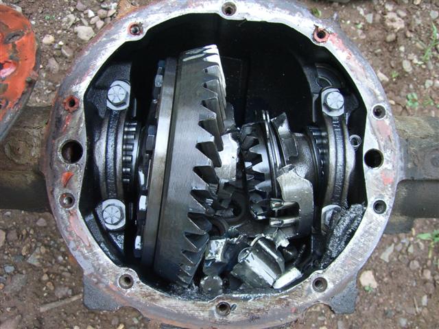
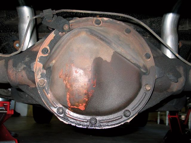
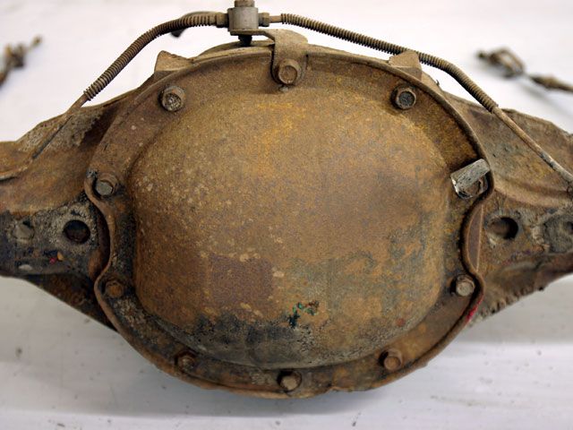
heres a picture another member posted,of what the factory 10 bolt rear differentials likely to look like in a few months with that engine and over 500 ft lbs of engine torque, if the tires get decent traction
yes Ive twisted more than my share of 10 and 12 bolt rears into scrap, and yes Id strongly suggest a ford 9" or a dana 60 swap
") .
.