wildcatlock said:
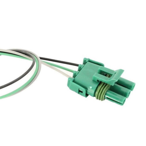
Ok guys, many of us have had a persistent code related to the maf. Either code 34,35, or 36. Some here have swapped anything and everything and still faught to fix these codes. Well I too had a persistent code. Mine was a code 34 - maf too high. Like most I tried everything....changed out and replaced the relays, tried a known good maf, went through the FSM checklist more times than I could count!!! Welll heres what I came up with. was searching around one day and came across a maf connector with pigtail. It was only 15 bucks and as I had already tried everything else and then some I figured why not. Swapped it out in about 45 minutes including soldering and heat shrink time. Old connector tested out good per FSM, but apparently the connections were worn or corroded to the point they wouldn't make good contact in the maf. After replacement code is gone and car runs better than ever.
So to all those out here who have the same persistent code and cant get it to stay cleared, you might give this a try. Our cars are getting old and wiring is getting brittle. Guess the connectors need a good looking over too, even if they test good. Hell for 15 bucks and about 45 minutes, if you've tried everything else, how can you go wrong.:cheers:
jktucker92 said:
There are books written out there that can give you the advantages / disadvantages of each system, but I'll try to keep it brief. In order to run as efficient as possible, you need to mix fuel and air at a specific mass ratio. 14.7:1 is the Stoichiometric ratio that is ideal, but richer mixtures can provide more power. With a MAF sensor, you measure the mass of the air flowing in the intake, which makes the calculation of how much fuel simple and accurate. The problem is the MAF sensors are more expensive than a simple pressure and speed sensor, especially early on. Also, the MAF sensors can be restrictive when you want to increase performance, so they are often removed in high performance applications. A speed density system uses the speed of the engine, manifold pressure, and temperature to calculate the mass of the air flowing into the intake and into the cylinder. This is pretty accurate, but not as accurate as a MAF sensor. As a result, the engines generally are tuned to run a little richer than the MAF systems to avoid damaging the engine by running too lean all the time.
Whether an engine is batch or sequential injected is a different, but related topic. In order to have sequential injection, the engine must be port injected, and the injector fires on each cylinder as each valve is opened. Batch systems can fire all the injectors on each revolution, or half one one revolution and the other half on the next. As it comes out of the injector, it's a fine mist, and the longer it is in the manifold, the more that mist becomes larger droplets, which burn less efficiently. Port injected systems are better than throttle body systems because their injectors are close to the ports and the fuel stays in the fine mist better.
The most efficient system is a MAF sequential injected system, which is why all new vehicles are MAF sequential injected systems.
the early corvettes like my 1985 came with a 160 baud processor speed, this was so slow that it took almost a full second to respond to sensor data,and make the next change required, making use of things like dry nitrous injection that in theory would rely on the engine sensing the overly lean fuel/air ratio a massive increase in oxygen to fuel ratio a sure way to burn pistons, simply because the early cpu processor speed was hopelessly slow. batch fire allowed the computer to control 4 injectors with a single control pulse ,effectively reducing the required processor speed by 75%
some of the early tpi injection intakes like the 1985 came with a 9th cold start injector whos only real function is to act as a choke and richen the fuel air ratio during cold engine starts
the function of the cold start injector on the 1985 tpi is to provide extra fuel, acting like a carb choke richening the fuel air ratio, if you just plug off the fuel rail and intake and remove the 9th injector it will still run OK just like a carburetor, without a choke will once its up to operating temperature, but it will be a P.I.T.A. to start on cool mornings and ALWAYS take a bit longer to start up, as would a carb engine without a choke because EFI doesn,t have the accelerator pump function where you can remove or bye-pass the symptoms by flooring the carb several times , to get the accelerator pump shot to richen the fuel air ratio.
but what you can do is upgrade the
absurdly slow 160 baud processor this meant the computer control responding to sensor input,could ad or remove fuel only a couple times a second the CPU has to a more current version which controls ALL the injectors and RICHENS all the pulse durations to all the injectors under cold start conditions, thus eliminating the need for the 9th injector or installing its feed or connectors, but obviously the rear of the drivers side fuel rail needs to be plugged if the 9th injector feed is removes as will the injector mount hole in the intake manifold if its been removed
data is sent at 8192 baud by 1989, or 51 TIMES FASTER, and by todays standards the 1989 processor speeds a joke itself.as current speeds are hundreds of times faster, allowing individual cylinders to be tuned independently hundreds of times a second
viewtopic.php?f=32&t=2825
https://www.rockauto.com/en/catalog...,exhaust+&+emission,mass+air+flow+sensor,5128
http://garage.grumpysperformance.com/index.php?threads/testing-1985-89-m-a-f-sensor.1475/#post-43635
https://www.zip-corvette.com/85-89-high-performance-adjustable-maf-sensor.html
85-89 High Performance Adjustable MAF Sensor
Re: MAF & code 34
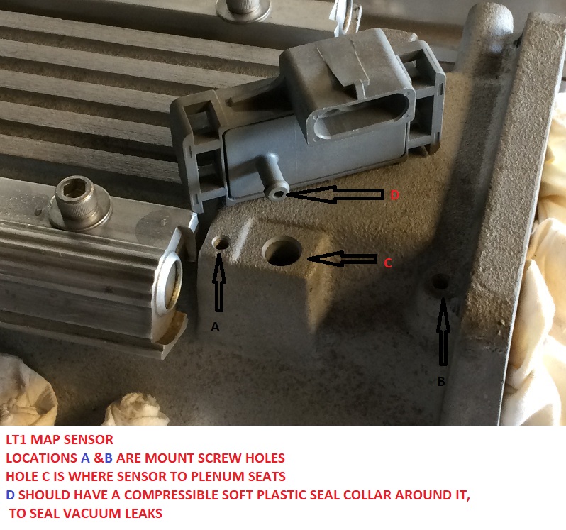
the threads linked below may help, but its more than likely a bad temp sensor or the TPS OR IAC is out of adjustment. so the first thing Id suggest is to adjust the TPS and IAC per the linked info and check for loose connections and vacuum leaks, and loose plenum and intake runner gaskets
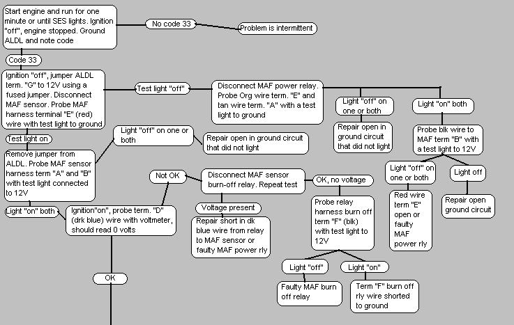
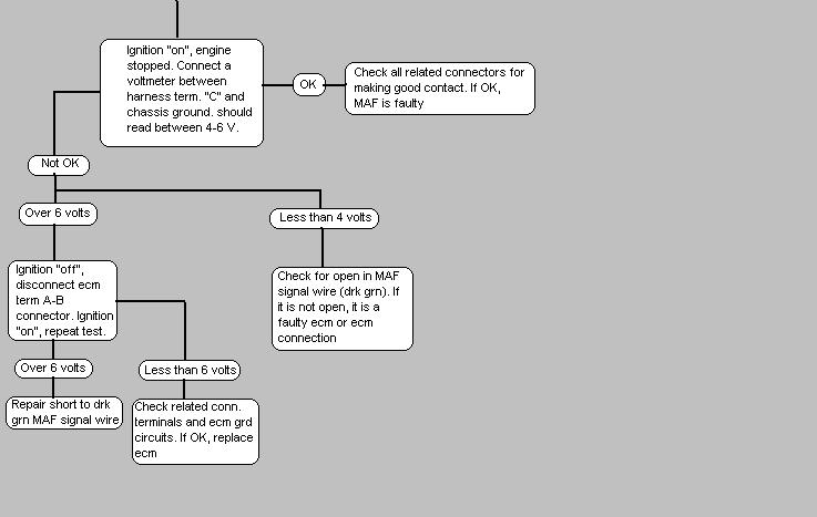
34 Mass Air Flow Circuit (1985-1990) Clean the throttle body. Check MAF connections. Replace MAF relay. Replace MAF Sensor. Possible ECM failure.
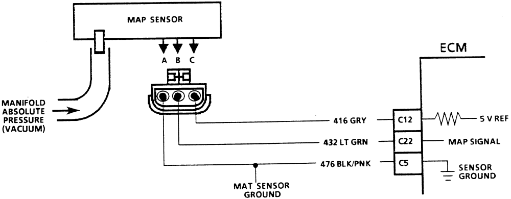
34 Manifold Absolute Pressure Low (1984) Check Vacuum hoses associated with MAP sensor. Check wiring and connections, particularly at ECM. Replace the sensor. Possible ECM failure.

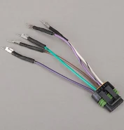
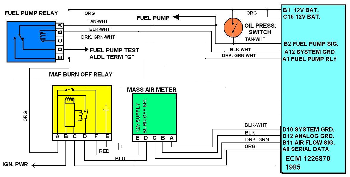
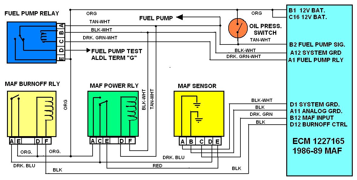
MAF SENSORS AND RELAYS ARE FREQUENT SOURCE OF INTERMEDIATE OR HARD TO ISOLATE RUN ISSUES ON EARLIER TPI CORVETTES SO CHECK THEIR FUNCTION
http://www.mamotorworks.com/corvette-c4 ... 6-893.html
https://www.zip-corvette.com/85-89-high-performance-adjustable-maf-sensor.html
85-89 High Performance Adjustable MAF Sensor
https://www.rockauto.com/en/catalog...,exhaust+&+emission,mass+air+flow+sensor,5128
https://www.autozone.com/videos/v/delphi-mafsensors-101/224995962/
Item Number: EH-521
heres a rather useful addition to the older c4 corvette tuning world, its a new (yes expensive)
but adjustable and thus some what tune-able MASS AIR FLOW SENSOR for the TPI corvettes
85-89 MAF TPI Systems
Below is a list of all the needed sensors to install a MAF TPI setup, and each of their functions.
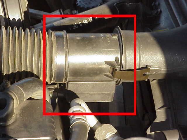
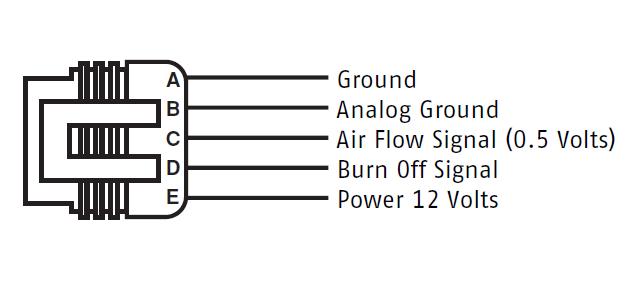
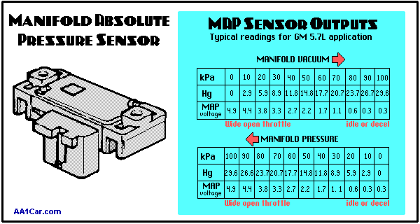
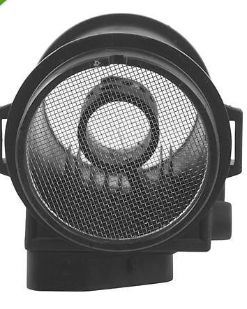
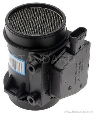
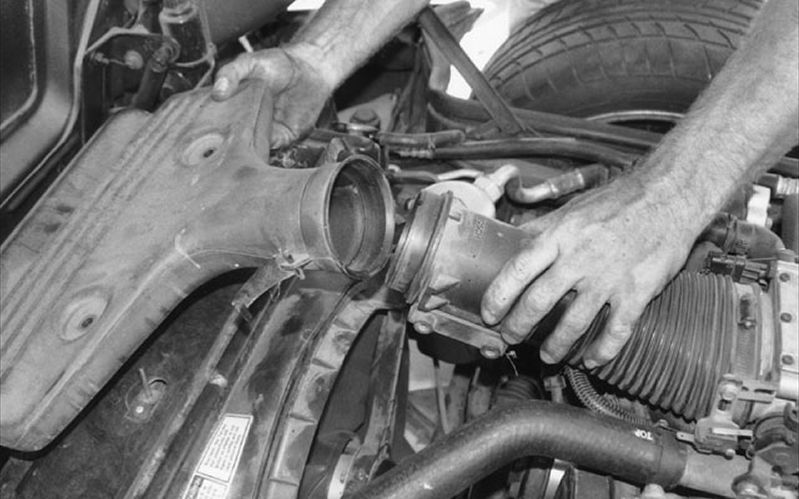
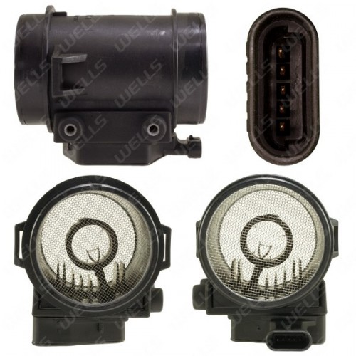
Mass Air Flow (MAF) Sensor: This sensor is responsible for measuring air volume and density. It is located in the air duct, before the throttle body. All of the air that the engine consumes must first pass through the MAF sensor. At the center of the MAF, is a very thin wire whose resistance increases as it goes up in temperature. A constant voltage is applied to this wire. Air being drawn through the MAF has the effect of cooling this wire, which lowers its resistance, and increases current. As you might suspect, the more air is drawn through the MAF sensor, the greater the current flow. It is important to note that hot dry air is less dense and has less mass than cool moist air. As a result, hot dry air will cool the wire less than cool moist air.
A circuit mounted on the MAF sensor serves to convert the current flow into a variable frequency square wave on 1985 models, which is sent to the ecm. MAF units from 86-89 models output a simple analog signal instead of using frequency modulation like the 1985 units. The ecm will calculate the amount of fuel needed depending on the signal from the MAF sensor. It is very important that there are no air leaks (from a ripped air duct for example) between the MAF and the throttle body.
Oxygen Sensor: Responsible for determining the amount of oxygen in the exhaust manifold. Depending on how much oxygen is in the exhaust, the ecm can determine whether or not the air/fuel mixture is rich or lean. The signal sent to the ecm by the ecm varies between 0.0 and 1.0 volts. An ideal mixture (also known as a Stoichiometric mixture) of 14.7:1 is represented by .450 volts. If the oxygen sensor voltage is below .450, then the air/fuel mixture is lean. Anything over .450 means the mixture is rich. Since the sensor is essentially just a switching device, it will be fluctuating alot between lean and rich. This is normal, and an indication that the sensor is in working properly.
Keep in mind however that oxygen sensors (except wideband oxygen sensors), are not very accurate below or above .450 volts. Exhaust gas temperature will affect the oxygen sensor reading as well. The sensor will not read properly until exhaust gas temperature reaches approximately 600 degrees Farenheit. If you have headers installed, it is a good idea to use a heated oxygen sensor (3 wire) instead of the usual single wire sensor. Headers usually place the oxygen sensor further down the exhaust stream, where exhaust temperatures are cooler. A heated oxygen sensor will heat itself, allowing a more reliable sensor reading than a single wire sensor. If you have factory exhaust manifolds, then the single wire sensor is adequate.
Oxygen sensors are a regular maintenance item, and should be replaced every 30,000 miles. When an oxygen sensor goes bad, it tends to read lean, and will not fluctuate very much. The ecm will attempt to correct this false lean condition by richening the mixture. This will cause poor driveability, and high gas consumption.
Knock Sensor: Also known as detonation sensor, it is responsible for sensing spark knock. Basically, thats when the fuel mixture ignites before the spark plug fires. The piston is moving upwards as this premature combustion takes place. Since fuel is used to cool down the combustion chamber, a lean condition causes the temperature to rise, and ignites the fuel mixture prematurely. This is very abusive on the engine internals, and reduces the life of any engine. The more powerful the engine, the greater the potential for damage. Detonation can be cause by a variety of things. One of the more common causes on TPI retrofits where prom changes have been made to the fuel or spark tables is a lean condition. It isn't always loud enough to be heard, so just because you don't hear any pinging, doesn't mean its not happening.
Detonation will cause a vibration to travel through the engine block. The sensor listens for this vibration at a certain frequency, and sends a signal to the ecm when the frequency is heard. This frequency is different depending on engine size. To prevent possible engine damage, the spark timing needs to be retarded when detonation is present. The sensor itself does not pull the timing back however. The ecm is in charge of retarding the timing, and will do so according to a series of settings inside the prom. The knock sensor is located on the passenger side of the engine block on factory applications. It can however be relocated to the driver side of the block if needed (header clearance for example). They are different depending not only on the size of the engine, but also the ecm being used. It is important that the correct sensor is used to avoid problems. Although it is possible to run the car without one, I strongly suggest against this. I have had customers come to me looking for a $45 knock sensor after spending several hundred dollars and an extra month of work rebuilding a blown engine due to detonation.
Throttle Position Sensor (TPS): Responsible for reporting to the ecm the position of the throttle blades. The ecm will receive a signal which can vary from 0.0 to 5.0 volts. At idle, the TPS should be read .54 volts (factory specification) unless it has been set to a different value inside the prom. If it does not read .54 volts and the idle TPS voltage setting has not been modified in the prom, then it should be adjusted. Under full throttle, it should output close to 5.0 volts. Throughout its range of motion, the voltage should climb steadily, without any jumps or falls. If it is not steady or has some fluctuations as it is moved through its range of motion, it should be replaced. This sensor is located on the passenger side of the throttle body.
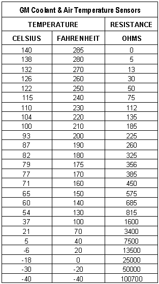
Coolant Temperature Sensor (CTS): This is basically a thermistor (means that it changes resistance with temperature) that supplies the ecm with the temperature of the engine coolant. This temperature reading is used for several important functions. The most notable is that the ecm adds extra fuel to an engine when its cold, and as the engine warms up, the extra fuel is reduced. This sensor mounts at the front of the intake manifold. The chart below shows the approximate resistance for this sensor in relation to temperature.
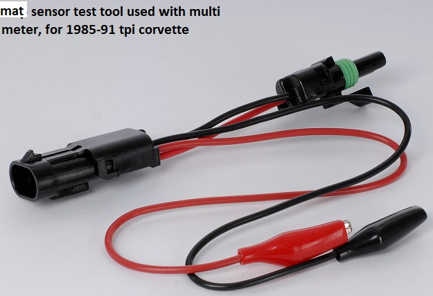
the later 1992-96 corvette lt1 used a MAT SENSOR
https://www.rockauto.com/en/catalog...,exhaust+&+emission,mass+air+flow+sensor,5128
http://garage.grumpysperformance.com/index.php?threads/odd-exhaust-temps-and-failed-smog-test.15817/
Intake Air Temperature Sensor (IAT): This sensor is also a thermistor (means that it changes resistance with temperature) that supplies the ecm with a temperature reading of the air being drawn into the engine. It is the same as the coolant temperature sensor on 86-92 models. The 1985 intake air temperature sensor used a different connector and cannot be used as a coolant temperature sensor because it had an exposed bulb. This sensor mounts underneath the plenum. The chart above shows the approximate resistance for this sensor in relation to temperature.
Idle Air Control (IAC) Valve: Although this is technically not a sensor at all, people often treat it as one. It is responsible for regulating the amount of airflow being admitted into the engine to adjust engine speed, particularly at idle and deceleration. The ecm controls the IAC at its discretion. The IAC works by moving a cone shaped pintle, which can extend and retract as needed to admit or block off incoming air. The valve moves the pintle in "steps". These steps are numbered and range from 0 to 160. A properly adjust throttle body should be idling when warm between 15-25 steps.
The IAC is used under a variety of conditions, not only at idle speed. The valve mounts on the bottom coolant plate of the throttle body.
Vehicle Speed Sensor (VSS): This is responsible for providing the ECM with the vehicle speed. It can be located either at the tailshaft of the transmission, or behind the speedometer on cars with a cable driven speedometer. It sends a 2k ppm (pulse per mile) square wave signal, and is needed for a variety of functions. It is absolutely critical for the ecm's learn mode, timing retard, emissions, torque converter lockup (automatic lockup transmissions only), idle speed control, and to avoid stalling on deceleration. It is possible to run without one. However, your car will NOT be street legal if you are required to retain emissions equipment, the ecm will not control the torque converter lockup, the ecm will not retard timing if you run into detonation, and it is possible to run into stalling /idle speed issues. In addition, the ecm will not adjust the fuel table properly as you drive (known as its "learning ability"). If the ecm does not know the vehicle speed it is assumed to be 0 mph.
If you still insist on not running a vss, I very highly suggest that the minimum vehicle speed for timing retard be brought down to 0 mph in the prom. The factory setting is 2 or 3 mph. If you don't bring this value down, and you do not run a vss, the ecm will NOT retard your timing under detonation.