NO!ndv said:I want to confirm visually telling the difference between a solid and hydraulic lifter.
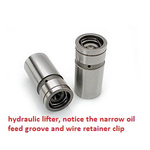
Is it true that a hydraulic lifter will have a clip around the inside edge where the solid will not?
Thanks
as to the lifters theres a few odd ones, (like the RHOADS FAST BLEED HYDRAULICS) WHICH work well
but frequently sound like less than perfectly adjusted solid lifters
that don,t follow these basic guide lines but probably 90% do
btw the best deal I found lately on basic hydraulic flat tappet lifters
http://www.summitracing.com/parts/sum-ht817/overview/
btw the best deal I found lately on basic hydraulic flat tappet lifters
http://www.summitracing.com/parts/sum-ht817/overview/
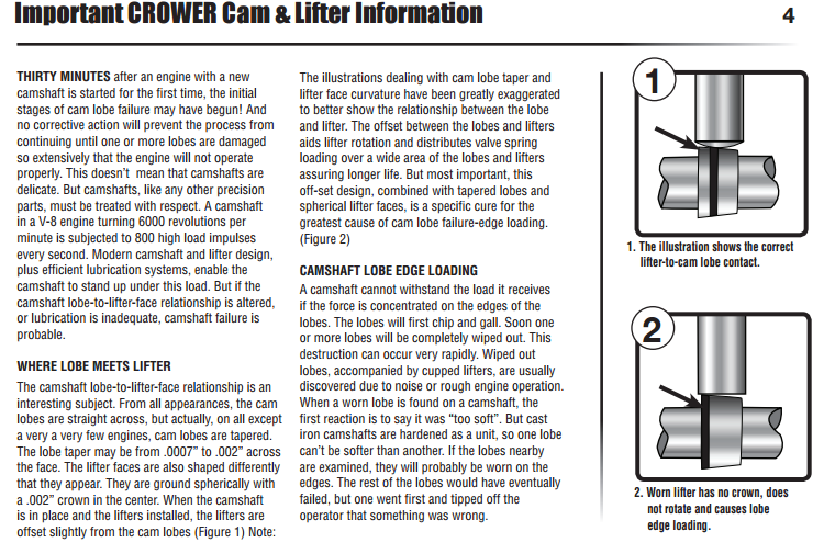
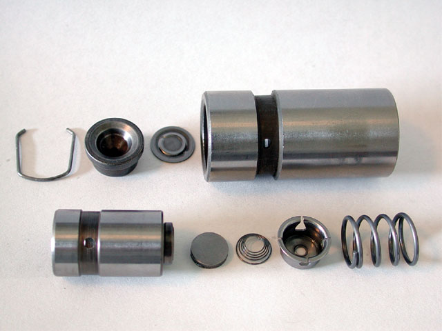
heres a crower solid
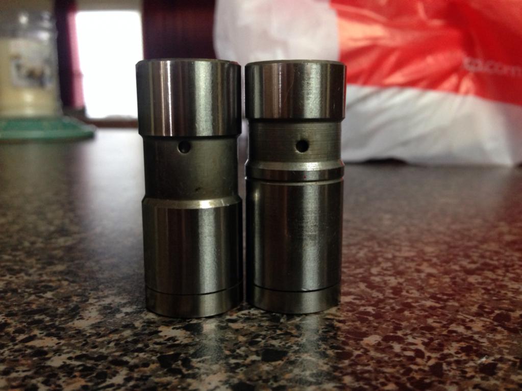
the better quality hydraulic and solid flat tappet lifters have hardened bases
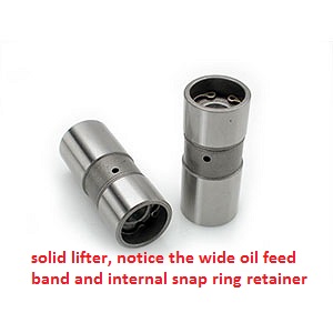
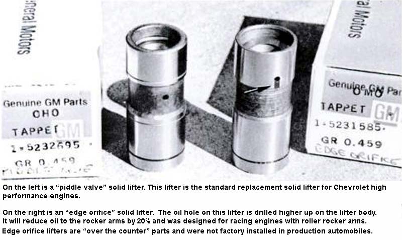
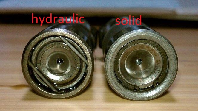
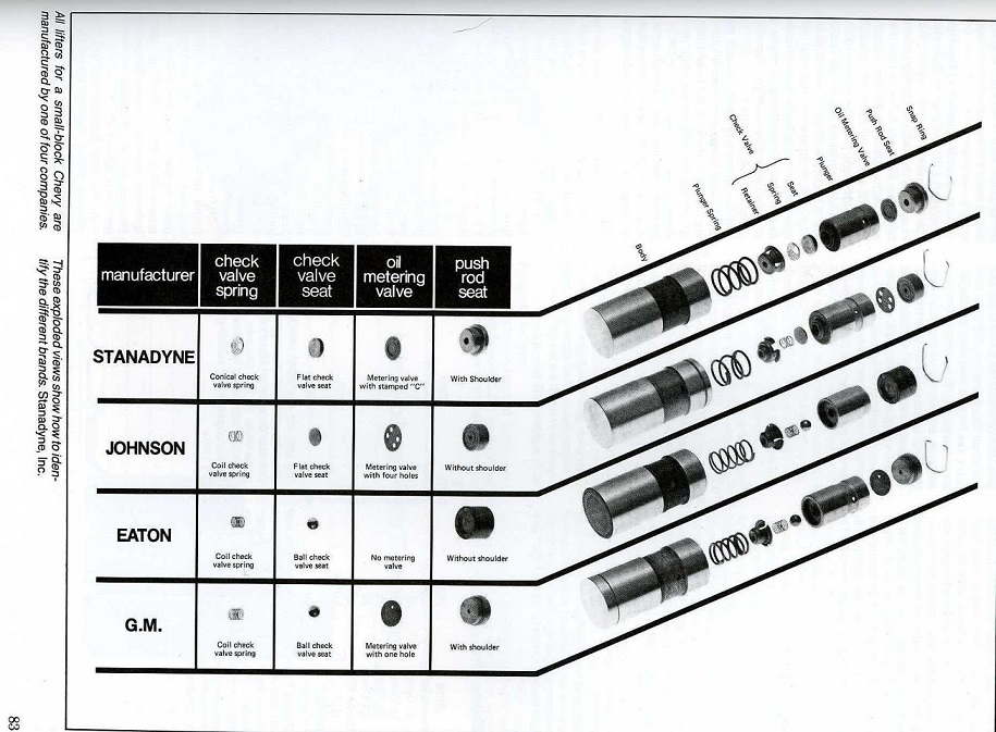
be aware that not all manufacturers are consistent, some lifters may have narrow or wide bands or retention clips of either design on either solid or hydraulic lifter design's ,but by far the majority go the route the pictures depict
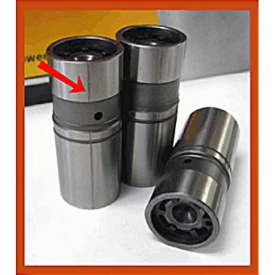
almost all hydraulic flat tappet lifters look like this type spring retention clip
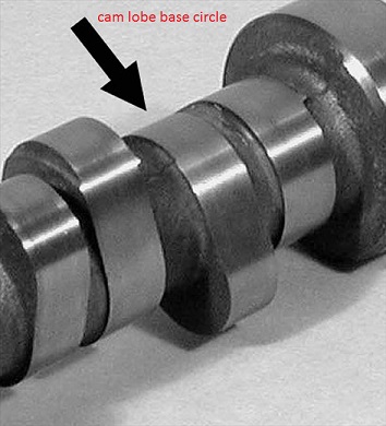
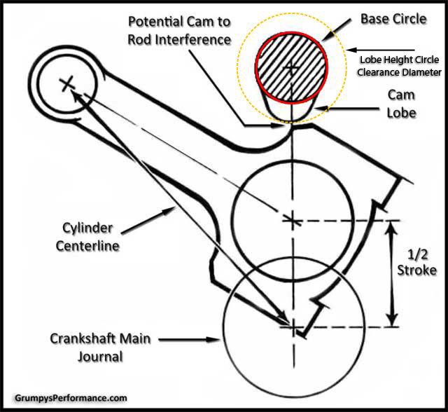
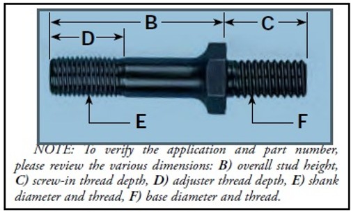
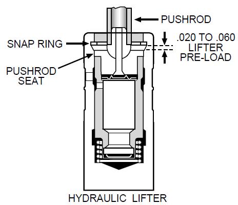
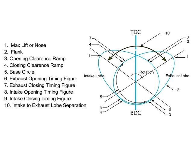
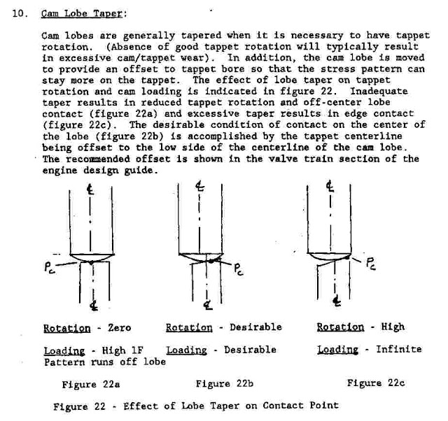
Youll occasionally have guys tell you that you can push down on a hydraulic lifter and it "GIVES" where a "SOLID" lifter WON,T, the problem is that the "GIVE" is in the lifter seat and only if the lifter is not up on the cam lobe where its already had the oil under the seat forced up the push rod, the HYDRAULIC lifter, push rod seat,in a hydraulic lifter is supported or floats on a seat of pressurized oil,in a running engine thats constantly being replaced, as the lifter rides over the cam lobe base circle and the resulting clearance allows the pressurized oil to re-fill the resulting void,created, once is forced out, by the push rod depressing the seat to force oil up the push rod to the rocker, in a non-running engine ,its not replaced so the seat stays depressed, the total distance the seat moves from full extended to fully depressed rarely exceeds .120, or just under 1/8 inch, look at the diagram below carefully, now think,common sbc rocker studs use a 3/8 24 thread pitch (AREA (E) IN DIAGRAM)thus at 24 threads per inch, theres roughly .041 thousandths movement in one full revolution of a rocker nut adjustment, yes theres a 1.5:1 rocker ratio, but even then your still only at .062.
and the seat will not re-seat or spring back, as theres zero oil pressure to force it back into place
ALEX said:Grumpy, I noticed my valve train got really noisy after I went to a test and tune nite at the track, I located the cause after careful inspection, one of the lifters had started coming apart,..what caused hydraulic lifters to come apart ?
most all hydraulic lifters have a floating push rod seat held in by a retainer clip, and supported by hydraulic oil pressure supplied by the engine oil pump, the combination of lack of enough valve spring to keep the lifter securely on the cam lobe at high rpm, and the impact forces of the lifter if its lofted or got flipped off the cam lobe and lost contact with the cams lobe and as the valve spring pressure regains control it slams back onto the cam lobe during valve float,and/ or combined with the lack of proper pre-load on the valve adjustment can effect this, I generally suggest a minimum of a 1/4 turn past the point where the lifter stops clicking at idle, and a 1/2 turn certainly won,t hurt most engines.
(entering valve float rpm which is usually in the case of many hydraulic lifters with stock valve spring load rates in or near 5800rpm-6200rpm)allows the floating lifter push rod seat to bounce against the retainer clip, eventually this tends to break or dislodge the clip, especially the weaker spring wire clips vs the c-clip style
read this
http://garage.grumpysperformance.com/index.php?threads/junk-hydraulic-lifters-mystery-solved.12263/
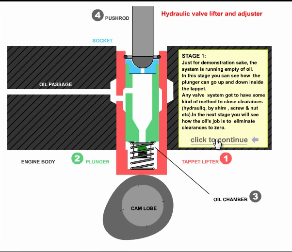
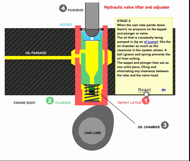
watch this video, it depicts the lifters movement as the cam lobe rotates under its base forcing it up as the lobes ramp, rotates under the lifter base,removing the clearance slack,
as it compresses the valve spring and forces the trapped oil, up the push rod and lifts the valve
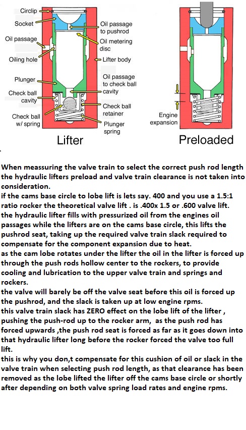
If you are concerned with measuring the clearance in the hydraulic lifter seat when selecting and measuring the correct valve train geometry,
so you can order the correct length push rods...
I don,t think you have the correct idea as to how hydraulic lifters work,
yes it is possible for an engine with hydraulic lifters to be pushed too operate at a high enough rpm that the time required for the lifter seat to fully depress and all the oil too be forced up to the push rod/rockers , to be so short that the lifter pumps up and the valves will have less seat time, ( sometimes one of several factors, like the lifter leaving the cam lobes surface as the inertial loads exceed the valve springs ability to maintain lifter too lobe contact, referred too or contributing to what is commonly referred too as valve float) but that has ZERO to do with selecting push rod length or proper valve train geometry, (remember at 6000 rpm the valve is lifted off its seat 50 times PER SECOND)
valve seat and back face angles ,valve diameter and valve lift and duration effect the flow thru the curtain area
keep in mind that valve may be forced off its seat, too full lift and re-seating 50 plus TIMES A SECOND at near 5500 rpm, so theres very little TIME for gases to move through the very restrictive space between the valve seat and valve edge
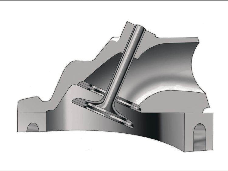
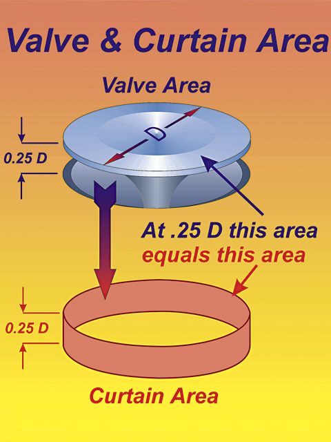
Calculating the valve curtain area
The following equation mathematically defines the available flow area for any given valve diameter and lift value:
Area = valve diameter x 0.98 x 3.14 x valve lift
Where 3.14 = pi (π)
For a typical 2.02-inch intake valve at .500-inch lift, it calculates as follows:
Area = 2.02 x 0.98 x 3.14 x 0.500 = 3.107 square inches
Last edited by a moderator:
 ). But you have to get your ear down close to hear it.